
Related Manuals for SDT International SDT170


Summary of Contents for SDT International SDT170
- Page 1 SDT170 SDT International sa-nv • Bd de l’Humanité 415 • B-1190 Brussels (Belgium) • Tel: +32(0)2 332 32 25 • info@sdt.be • www.sdtultrasound.com MAN.170.EN--04--SDT170-user-manual-Eng.docx 1/141...
- Page 2 Seventh edition. All rights reserved: No one is permitted to reproduce or duplicate, in any form, the whole or part of this document without the written permission of SDT International n.v. s.a. The information herein is believed to be accurate to the best of our knowledge.
-
Page 3: Table Of Contents
Table of contents The user’s manual ................4 The package ..................5 Recharging the battery pack ............6 Using the SDT 170 S and S+ ............8 Using the SDT 170 M and M+ ............12 Using the SDT 170 MD ..............20 Presentation .................. -
Page 4: The User's Manual
While every effort was made to present a true and accurate text, modifications and/or improvements to the product described herein can be made at any time without corresponding changes being made to the manual. This User’s manual and its contents remain the inalienable property of SDT. MAN.170.EN--04--SDT170-user-manual-Eng.docx 4/141... -
Page 5: The Package
Shoulder strap Contact probe and needle Center punch MPlus software (1) DataManager software (2) Cable RS232 (1) Data transfer from the unit to the PC. Delivered on a 3 ½’’ floppy disk. (2) Delivered on Cd-rom with user manual. MAN.170.EN--04--SDT170-user-manual-Eng.docx 5/141... -
Page 6: Recharging The Battery Pack
3. Recharging the battery pack The battery pack must be charged before its first use. The charger must be unplugged from the mains before recharging a new battery, in order to reset the internal timer. 3.1 R ECHARGING THE BATTERY PACK IN THE UNIT The connection of the charger to the unit. - Page 7 The charging cycle will take about 5 to 6 hours to be completed. The end of charging is done when the charger light is off Once charging over, replace the charged battery pack in the unit, like previously indicated. Connection of the battery charger onto the battery pack. MAN.170.EN--04--SDT170-user-manual-Eng.docx 7/141...
-
Page 8: Using The Sdt 170 S And S
4. Using the SDT 170 S and S+ The chapter allows a quick use of the SDT 170 S and S+. It is nevertheless highly recommended to read carefully the whole manual before using the equipment. This chapter can therefore be considered has a quick reference guide. 4.1 R ECHARGING ON THE EQUIPMENT Refer to the chapter 3. -
Page 9: Connecting The Optional External Sensor
It can only be used to hear the ultrasounds signals. If the standard frequency band (38.4 kHz) if sufficient, go to point 4.7. If not, select the new frequency band, as follows: Select the main menu with MAN.170.EN--04--SDT170-user-manual-Eng.docx 9/141... -
Page 10: Selection Of The Amplification Level
A at the bottom of the screen. When the SDT170 receives ultrasonic sounds from a source, set the amplification level to have no arrow on the screen. When no ultrasonic signal is present, set the amplification to A = 80. -
Page 11: Taking A Measurement
The screen indicates the measure. The measurement screen of the SDT 170 S+ displays a digital measurement. 4.9 S WITCHING OFF Briefly press the key. Note: the unit will also automatically switch off after a pre-programmed period. Fix the sensor protective cap. MAN.170.EN--04--SDT170-user-manual-Eng.docx 11/141... -
Page 12: Using The Sdt 170 M And M
Recharge the battery; see chapter 3. 5.3 T HE SCREEN AFTER POWER ON If the SDT170 M or SDT 170 M+ works with the: Continuous function, the screen is as shown below (see paragraph 5.7). -
Page 13: Connecting The Optional External Sensor
In this mode, the SDT 170 can not be used to measure or to store measurements. It can only be used to hear the ultrasounds signals. If the standard frequency band (38.4 kHz) is correct, go to point 5.7. If not, select the new frequency band, as follows. MAN.170.EN--04--SDT170-user-manual-Eng.docx 13/141... -
Page 14: Selecting The Continuous/Max Value Function
A at the bottom of the screen. When the SDT 170 receives ultrasonic sounds from a source, set the amplification level to have no arrow on the screen. When no ultrasonic signal is present, set the amplification to A = 80. MAN.170.EN--04--SDT170-user-manual-Eng.docx 14/141... -
Page 15: Taking A Measurement
SDT 170 stops measuring. The display shows the highest value recorded while the key was pressed. To make a new measurement and erase the previous maximum value, just press this again. If needed, store the measured value. Refer to next paragraph. MAN.170.EN--04--SDT170-user-manual-Eng.docx 15/141... -
Page 16: Storing A Measured Value
The data regarding the selected reading is displayed. Push until return to the measurement screen. 5.12 E RASING A STORED VALUE To erase a stored value in the data logger memory, proceed as follows: From the main menu push MAN.170.EN--04--SDT170-user-manual-Eng.docx 16/141... -
Page 17: Switching Off
Push until return to the measurement screen. 5.13 S WITCHING OFF Briefly press the key. Note: the unit will also automatically switch off after a pre-programmed period. Fix the sensor protective cap. MAN.170.EN--04--SDT170-user-manual-Eng.docx 17/141... -
Page 18: Transfert Of Data From The Sdt 170 M+ To The Pc
SDT 170 M+ will be saved. b) In the field File name, enter the name of the file (txt file) under which the data coming from the SDT 170 M+ will be saved. c) Click Open. Click the button COM Port Setup. MAN.170.EN--04--SDT170-user-manual-Eng.docx 18/141... - Page 19 SDT 170 M+ towards the PC. The message No response of SDT170 is displayed when a fault occurs during the transfer due to at least one of the following causes : - SDT 170 M+ is off.
-
Page 20: Using The Sdt 170 Md
The message Battery charge too low flashes on the screen when the battery pack’s charge is to low. Recharge the battery; see chapter 3. 6.3 T HE SCREEN AFTER POWER ON If the SDT170 works with the: Continuous function, the screen is as shown below (see paragraph 6.6). ... -
Page 21: Connecting The Optional External Sensor
If the standard frequency band (38.4 kHz) if sufficient, go to point 6.7. If not, select the new frequency band, as follows. Select the main menu with Select Settings... with and push Select Sensor options with and push Select Discov.fr.band with and push Set the frequency band with MAN.170.EN--04--SDT170-user-manual-Eng.docx 21/141... -
Page 22: Selecting The Continuous/Max Value Function
When the SDT 170 receives ultrasonic sounds from a source, set the amplification level to have no arrow on the screen. When no ultrasonic signal is present, set the amplification to A = 80. Note: it is advisable to begin the measurement with the maximal amplification (A = 80). MAN.170.EN--04--SDT170-user-manual-Eng.docx 22/141... -
Page 23: Selection Of The Route
SDT 170 stops measuring. The display shows the highest value recorded while the key was pressed. To make a new measurement and erase the previous maximum value, just press this again. If needed, store the measured value. Refer to next paragraph. MAN.170.EN--04--SDT170-user-manual-Eng.docx 23/141... -
Page 24: Storing A Measured Value
The type of sensor, date, time and value are also displayed. Push to store the data which are now stored in memory. The measurement screen is automatically displayed ready for a new measurement. MAN.170.EN--04--SDT170-user-manual-Eng.docx 24/141... -
Page 25: Viewing A Previous Stored Value
To erase a stored value in the data logger memory, proceed as follows: From the main menu push With , choose Erase data and push With , choose, for the previously selected route, the point to be erased and push If exist, the previous recorded reading(s) is (are) displayed. MAN.170.EN--04--SDT170-user-manual-Eng.docx 25/141... -
Page 26: Switching Off
Note: the unit will also automatically switch off after a pre-programmed period. Fix the sensor protective cap. 6.15 T SDT 170 MD RANSFER OF THE DATA FROM THE TO THE Refer to the manual of the DataManager application. MAN.170.EN--04--SDT170-user-manual-Eng.docx 26/141... -
Page 27: Presentation
7. Presentation 7.1 O SDT 170 PERATING PRINCIPLE OF THE General Ultrasonic waves are sound waves beyond the range of human hearing (>20 kHz). To be detected, we need to use equipment like the SDT 170, with the capability to receive ultrasonic frequencies and convert them to corresponding audible sounds. -
Page 28: The Various Versions Of The Sdt 170
Regularly and for different reasons, the software version from the SDT 170 ultrasonic detector can be updated. One of these reasons, is the implementation of a new sensor in our SDT product line, another reason can be the addition of a MAN.170.EN--04--SDT170-user-manual-Eng.docx 28/141... - Page 29 SDT 170 MD: this unit can memorize 128 routes. Each route can have up to 1,000 points. Each point can memorize up to 4 measurements. One route can therefore memorize 4,000 data. The route 000 works as a scratch pad and cannot receive a preloaded route. MAN.170.EN--04--SDT170-user-manual-Eng.docx 29/141...
-
Page 30: Front And Back Side (Full View)
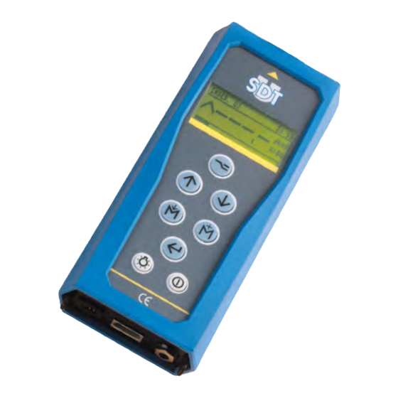
Battery charger connector. LCD display. RS 232 connector and cap. Holster. Audio output connector (headphone Keyboard. minidisc, PC, analyzer). Backlight switch. Sensor protective cap. On/Off switch. External sensor connector. Strap carrying rings. The visible elements of the SDT 170. MAN.170.EN--04--SDT170-user-manual-Eng.docx 30/141... -
Page 31: The Keyboard (All Versions)
On/Off switch. First key press: switch on the unit. Second key press: switch off the unit. The unit switches off automatically if no buttons are touched on the keypad within pre-defined period of time set by the user. MAN.170.EN--04--SDT170-user-manual-Eng.docx 31/141... -
Page 32: The Display
Battery level indicator. 100% black corresponds to a fully charged battery. Time (Hour) Current time. Used memory In % of the RAM used. 100% = fully used memory. Date Current date. Maximum readable value Full scale measurement. MAN.170.EN--04--SDT170-user-manual-Eng.docx 32/141... - Page 33 %. The following table shows the icons used. Icon Signification Date in the local format. Remaining capacity of the battery. 100% black means fully charged battery. Local time. Used capacity of the memory. Example of battery capacity remaining. 029 -030 MAN.170.EN--04--SDT170-user-manual-Eng.docx 33/141...
- Page 34 The measurement unit (except S version) The measurement unit is shown on the right side of the display, such as dBµV. The measurement scale (S version only) It varies according to the amplification level as shown in the following table. MAN.170.EN--04--SDT170-user-manual-Eng.docx 34/141...
- Page 35 So, with an amplification set to 40, all noises lower than 19 dB will not be displayed. It is the reason why the amplification level must be set to 80 for small leak detection. MAN.170.EN--04--SDT170-user-manual-Eng.docx 35/141...
-
Page 36: The Bottom Plate View
SDT 170. Due to the active interaction between the charger and the battery/equipment, only this charger can be used to charge the batteries. Connecting another charger will do serious damage to the equipment and void the warranty. MAN.170.EN--04--SDT170-user-manual-Eng.docx 36/141... -
Page 37: The Front View
For that purpose, the internal sensor is protected by a metal cap which has to be fitted if the sensor is not in use. Warning: when using the internal sensor, do not forget to remove the protection cap (rep. 2). MAN.170.EN--04--SDT170-user-manual-Eng.docx 37/141... - Page 38 The internal airborne ultrasound sensor is automatically disconnected when an external sensor is connected. The sensor families (ultrasonic or non ultrasonic) can be connected on the various SDT170 as follows: Ultrasonic sensors Non ultrasonic sensors...
-
Page 39: The Back Side
The serial number of the SDT 170 The serial number of the SDT 170 is visible in the battery compartment, on the back side of the unit. 1. Bar code and serial number of the detector. Localization of the serial number of the detector. MAN.170.EN--04--SDT170-user-manual-Eng.docx 39/141... -
Page 40: General View Of Accessories
7. Presentation 7.9 G ENERAL VIEW OF ACCESSORIES General view of accessories to be mounted on the SDT 170. MAN.170.EN--04--SDT170-user-manual-Eng.docx 40/141... -
Page 41: The Main Menu (All Versions)
8. The Main menu (all versions) 8.1 A CCESS TO THE MAIN MENU Switching on the equipment by pressing the key. Once the equipment switched on, the self-test is started and takes about two seconds to finish. If no problem or fault is detected during this test, the unit will place itself into the measurement mode. -
Page 42: The Main Menu Screen
LCD display’s contrast, displays backlighting timer, auto power down timer, language, type of measurement system, unit of measurement relative to temperature and frequency range (only available when a contact probe is attached to the equipment). See chapter 12. MAN.170.EN--04--SDT170-user-manual-Eng.docx 42/141... -
Page 43: Main Function Tree
Activates the backlight. This key is available at any time. Switch of the equipment. This key is available at any time. AIN FUNCTION TREE It is displayed on next page. Some screens are not available on all models. Refer to this manual. MAN.170.EN--04--SDT170-user-manual-Eng.docx 43/141... - Page 44 Contrast Page 59 Backlight Page 59 Auto Pwr Dwn Page 60 Language… Page 61 Iso/Imperial Page 61 Auto Increment Page 62 System info Page 63 General tree of the menus. Some screens are not available on all models. MAN.170.EN--04--SDT170-user-manual-Eng.docx 44/141...
-
Page 45: The Select Route Menu (Md Only)
9. The Select Route menu (MD only) This menu is only available when at least, one route has been uploaded from the PC. Refer to the DataManager - User’ Manual to learn how to transfer a route, to or from the collector (SDT 170 MD). The route concept is explained in the Chapter 23. -
Page 46: Using A Route
Once the route chosen according to the previous paragraph, return to the measuring screen thanks to the key. The unit waits for its measurements according to the preloaded program. Chapter 6, Using the SDT 170 MD, explains how to use the SDT 170 MD with a preloaded route. MAN.170.EN--04--SDT170-user-manual-Eng.docx 46/141... -
Page 47: The View Data Menu (M, M+ And Md)
10. The View Data menu (M, M+ and MD) This menu allows the viewing of the stored data for a given route already selected in the Select route menu. It permits the user to display for any memory number, the stored memory contents (four last values only). It is assumed that measured data have been previously stored. -
Page 48: Viewing A Data With The Sdt 170 Md
No measurement ; in this case, press again the key to return to the previous display. Press shows a more detailed screen; see paragraph Detailed information below. Return to the previous menus by pressing the key. MAN.170.EN--04--SDT170-user-manual-Eng.docx 48/141... -
Page 49: Detailed Information
Move the inverted selection line upwards. The first number is the last measurement made. Move the inverted selection line downwards. The first number is the last measurement made. Validates the selected memory number and displays more details about the measurement. MAN.170.EN--04--SDT170-user-manual-Eng.docx 49/141... -
Page 50: The Erase Data Menu (M, M+ And Md)
11. The Erase Data menu (M, M+ and MD) This menu allows the removing of the stored data. The data to be erased will be: With a SDT 170 MD, one of the current uploaded route. With a SDT 170 M or M+, one of the measurement point (0 to 999). 11.1 A CCESS THE RASE... - Page 51 10. The View Data menu The active keys are: Function Return to the previous menu without erasing the data. Erasing the data and return to previous menu. The various screens displayed when erasing a data. MAN.170.EN--04--SDT170-user-manual-Eng.docx 51/141...
-
Page 52: The Settings Menu (All Versions)
12. The Settings menu (all versions) This menu allows the configuration setting of the detector, such as sensor options, date and internal clock, contrast of the display, duration of the backlighting, delay of the auto power down, etc. 12.1 A CCESS THE ETTINGS MENU ... -
Page 53: Sensor Options
The bar graph shows the instant level which varies continuously but the display only shows the maximal measurement when the is depressed. If necessary, the maximal measurement can be stored. The picture, on next page, shows the influence of the choice. MAN.170.EN--04--SDT170-user-manual-Eng.docx 53/141... - Page 54 The band width is always 2 kHz from the central displayed frequency. This allows the user to characterize phenomena on another frequency. This option is available with all ultrasonic sensors except the contact probe and the parabolic sensor. MAN.170.EN--04--SDT170-user-manual-Eng.docx 54/141...
- Page 55 To upper the central band frequency. To increase the amplification level. To decrease the amplification level. In this mode, the SDT 170 can not be used to measure or to store measurements. It can only be used to hear the ultrasounds signals MAN.170.EN--04--SDT170-user-manual-Eng.docx 55/141...
- Page 56 Enter, validate choice and return to the measurement display. With a sound level meter (dbA) The following menu is displayed. The menu with sound level meter. The selection acts as follows: Slow: slow reaction to sound peaks. Fast: fast reaction to sound peaks. MAN.170.EN--04--SDT170-user-manual-Eng.docx 56/141...
- Page 57 FAHRENHEIT or RANKINE: in the English Imperial system, one of both scales can be used. TC J. K: this function defines the type of temperature probe used for temperature measurement. TEMP. TC. J.: -40 °C to +750°C. TEMP. TC.K: -40°C to +1500 °C. MAN.170.EN--04--SDT170-user-manual-Eng.docx 57/141...
-
Page 58: Clock/Date
Return to the parameter menu, without taking into account eventual changes. Increment the inverted field. Hold key for auto increment. Decrement the inverted field. Hold key for auto decrement. Go to the next field to be modified. Enter, validate values and return to the settings menu. MAN.170.EN--04--SDT170-user-manual-Eng.docx 58/141... -
Page 59: Contrast
The backlighting timer restarts each time a key is pressed. When no key is pressed for the pre-programmed time, the backlighting will switch off automatically. The display will show a screen similar to the one above. The auto power off timer is adjustable between 1 and 100 seconds. MAN.170.EN--04--SDT170-user-manual-Eng.docx 59/141... -
Page 60: Auto Pwr Dwn
Return to the parameter menu, without taking in to account eventual changes. Increases the auto power off timer. Hold key for auto increment. Decreases the auto power off timer. Hold key for auto decrement. Enter, validate the adjusted auto power off timer’s value, and return to the settings menu. MAN.170.EN--04--SDT170-user-manual-Eng.docx 60/141... -
Page 61: Language
IMPERIAL: the measurements will display the English imperial measurement system. The mass flow sensor will read in SCFM (Standard Cubic Foot Minute). Temperature will read in degrees Fahrenheit or in degrees Rankine depending upon the setting. Example of screen that permits to change the measurement system. MAN.170.EN--04--SDT170-user-manual-Eng.docx 61/141... -
Page 62: Auto Increment
The Auto increment menu can be settled on OFF or ON. The active keys are: Function Return to the previous menu. Select Yes or No. Select Yes or No. Enter, validates the choice and return to the settings menu. MAN.170.EN--04--SDT170-user-manual-Eng.docx 62/141... -
Page 63: The System Info Menu
13. The System Info menu This menu permits the visualization of the system information and is a sequence of five consecutive screens. 13.1 F IRST SCREEN It consists of information relative to the: Type of equipment. (S: Standard, S+: Standard+, M: Multifunctional, M+: Multifunction+, MD: Multifunctional-DataManager). -
Page 64: Fourth Screen
The display shows the type of the connected sensor, as well as its serial number. Example of the complementary information (fifth screen). 027E After this fifth screen, the measurement screen is displayed. For all the screens, the active keys are MAN.170.EN--04--SDT170-user-manual-Eng.docx 64/141... -
Page 65: The Battery Pack
The battery packx... - Page 66 12. The Settings menu MAN.170.EN--04--SDT170-user-manual-Eng.docx 66/141...
-
Page 67: Technical Considerations
14. Technical considerations 14.1 I MPORTANT NOTE The battery packs are charged in the factory for test purpose, but are discharged before being dispatched, because of international air transport legislation. At reception, the battery packs should be reloaded during at least five hours. Optimal functioning will be obtained after several (3 minimum) full reloads. -
Page 68: The Battery Charger
The status indicator light When the battery charger is connected to the power supply, it informs the user of its charging status by means of the status light. The definitions of the status light are shown in the following table: MAN.170.EN--04--SDT170-user-manual-Eng.docx 68/141... - Page 69 The charging of the battery pack must always be done in a cool place, for example, room temperature (out of the sun or away from any heating system). MAN.170.EN--04--SDT170-user-manual-Eng.docx 69/141...
-
Page 70: Recharging The Battery Pack
15. Recharging the battery pack 15.1 R ECHARGING IN THE UNIT The battery pack can be charged while still in the unit. The connection of the charger to the unit. Charging will be done transparently to the operation of the unit. The advantage is the possibility to charge the battery pack while the unit is in use. -
Page 71: Recharging Out Of The Unit
Plug the battery charger in the mains socket. The charging cycle will take about 5 to 6 hours to be completed. Once charging over, replace the charged battery pack in the unit, like previously indicated. MAN.170.EN--04--SDT170-user-manual-Eng.docx 71/141... -
Page 72: Battery Discharged Message
Optimal functioning will be obtained after several (3 minimum) full reloads. Moreover, a battery might be never charged if the charger is not unplugged from the mains between two charges; the internal timer is so never reset. MAN.170.EN--04--SDT170-user-manual-Eng.docx 72/141... - Page 73 15. Recharging the battery pack MAN.170.EN--04--SDT170-user-manual-Eng.docx 73/141...
-
Page 74: Sensors And Options
Sensors and optionsx... -
Page 75: Technical Specifications
Technical specifications MAN.170.EN--04--SDT170-user-manual-Eng.docx 75/141... -
Page 76: Internal Ultrasonic Sensor
16. Internal ultrasonic sensor 16.1 S VERSION How to read the displayed data The orientation of the main icons on the S version. N° Function Remarks Type of sensor Type of sensor used / connected. Bargraph Visual indication of the measured values. Amplification adjustment Optimal amplification when no arrow shown. -
Page 77: S+, M, M+ And Md Versions
Technical Data Item Data Function & type Open type ultrasonic sensor Bandwidth ± 2 kHz at -6 dB Frequency 40 kHz ± 1 kHz Sensitivity -65 dB/V/µbar at 40 kHz Total beam angle 55° typical at -6 dB MAN.170.EN--04--SDT170-user-manual-Eng.docx 77/141... -
Page 78: External Ultrasonic Sensors
17. External ultrasonic sensors They can be connected on all versions (S, S+, M, M+ and MD). It is to be reminded that the detector SDT 170 will recognize the presence of the sensor and will automatically change to the appropriate settings, scales and units. It is insistently advised to refer to paragraph Important note concerning the plugging to the connector on page 113 regarding the connecting procedure, in order to avoid any premature deterioration of the connector... -
Page 79: Operating Mode
Besides gear tooth meshing and bearing problems, this mode detects defects such as: imbalance, misalignment and coupling failures. MAN.170.EN--04--SDT170-user-manual-Eng.docx 79/141... - Page 80 ) between US, MEC or SLOW MEC mode. Confirm your and down arrow ( choice by pushing the key. The menu with a contact probe. At the top of the LCD display you will see Contact –US-, Contact –M- or Contact –S-. MAN.170.EN--04--SDT170-user-manual-Eng.docx 80/141...
- Page 81 The LCD display contains the same icons as described in previous paragraphs. Type of sensor connected (here, a contact probe). Selected mode (S, M or US). Data (amount of ultrasonic sounds) is given in dBµV. The specific icon with an ultrasonic contact probe. MAN.170.EN--04--SDT170-user-manual-Eng.docx 81/141...
-
Page 82: Flexible Sensors
2 kHz at -6 dB Frequency 40 kHz ± 1 kHz Sensitivity -65 dB/V/µbar at 40 kHz Length 550 mm or 820 mm (without cable) Diameter 20 mm external 16 mm internal Cable length coiled 0,5 m to 2 m MAN.170.EN--04--SDT170-user-manual-Eng.docx 82/141... -
Page 83: Parabolic Sensor
The dish is transparent to easy visualize the object while measuring. For this same purpose of “pin pointing the object to measure” this parabolic concentrator has two sights: a “rifle-sight-shaped” sight and a very effective laser pointer sight. MAN.170.EN--04--SDT170-user-manual-Eng.docx 83/141... - Page 84 Material Handgrip Aluminum covered with antiskid grip Weight Approx. 0.8 kg. Parabola Max. Ext. Dia. 275mm Parabola Nominal Dia. 250mm Parabola length 193,5mm (with handgrip 90°angled) Fitting As separate unit or fitted on the SDT 170 with knurled nut MAN.170.EN--04--SDT170-user-manual-Eng.docx 84/141...
-
Page 85: Magnetic Sensor
The LCD display contains the same icons as usual. The sole difference is: Cable US: a cable for ultrasonic sensor is connected between the sensor and the detector. dBµV: the data (amount of ultrasonic sounds) is given in dBµV. MAN.170.EN--04--SDT170-user-manual-Eng.docx 85/141... -
Page 86: Threaded Sensor
Permanent control of mechanical units and predictive maintenance. Control of bush, motor, pumps, valve, steam trap, condensate purge. Description The sensor is equipped with a thread (M8) and a NBC connector. View of the threaded sensor. MAN.170.EN--04--SDT170-user-manual-Eng.docx 86/141... - Page 87 The LCD display contains the same icons as usual. The sole difference is: Cable US: a cable for ultrasonic sensor is connected between the sensor and the detector. dBµV: the data (amount of ultrasonic sounds) is given in dBµV. The icon with an ultrasonic external threaded sensor. MAN.170.EN--04--SDT170-user-manual-Eng.docx 87/141...
-
Page 88: Open Sensors
3 kHz at -6 dB Frequency 40 kHz ± 1 kHz Sensitivity -70 dB/V/µbar (14 mm) and -65 dB/V/µbar (20 mm) at 40 kHz Length 50 mm (without cable) Diameter 14 mm or 20 mm external Cable length 2,5 m MAN.170.EN--04--SDT170-user-manual-Eng.docx 88/141... -
Page 89: Closed Sensors
Closed sensor means waterproof sensor. Two models are available: 13 and 23 mm. Description Each of these sensors is supplied with a 2.5 m / 8.2 ft cable, equipped with a 7 pin LEMO connector. View of the closed sensors 13 and 23 mm. MAN.170.EN--04--SDT170-user-manual-Eng.docx 89/141... - Page 90 Indicates the type of sensor connected. The information depends of the sensor: closed sensor 13 mm, closed sensor 23 mm. Indicates the data (amount of ultrasonic sounds) given in dBµV. The specific icon with an ultrasonic external closed sensor. MAN.170.EN--04--SDT170-user-manual-Eng.docx 90/141...
- Page 91 17. External ultrasonic sensors MAN.170.EN--04--SDT170-user-manual-Eng.docx 91/141...
-
Page 92: Adaptators For Ultrasonic Sensors
18. Adaptators for ultrasonic sensors 18.1 E (EDS) XTENDED DISTANCE SENSOR Main field of application This cone form concentrator is used for leak and discharge detection with subtle ultrasonic sounds. Description Foreseen with a screw thread, this adapter can be screwed on the internal sensor of the unit and allows a better detection at an average distance with a good precision approach. -
Page 93: Lube Adapter
Listening to bearing, bush. Description Connected to the contact probe and fixed on the top of the pump flexible to grease, this adapter allows controlling the efficiency level of greasing in real time. View of the lube adapter. MAN.170.EN--04--SDT170-user-manual-Eng.docx 93/141... -
Page 94: Ultrasonic Transmitters
19. Ultrasonic transmitters 19.1 SDT 200 mW TRANSMITTER Main field of application It is the tightness control of small volumes which cannot be pressurized or depressurized. Description This is a small portable ultrasonic transmitter, equipped with one transducer and an internal rechargeable NiCd battery. The transmitter is available in directional and bi-sonic modes. -
Page 95: Sdt 8 (8 X 125 Mw) Transmitter
2.5 hours at 20 °C Charging time 6 hours Dimensions 160 x 100 x 95 mm (6.29 x 4 x 3.75 inches) (L x W x H) Weight 1.5 kg (3.3 lb) Operating temp. -10 to +50 °C (14 to 122 °F) MAN.170.EN--04--SDT170-user-manual-Eng.docx 95/141... -
Page 96: Sdt 8 (8 X 125 Mw) Multisetting Transmitter
A 6 position selector allows the choice of the ultrasonic power. This combination is an accurate and reliable tool for testing the tightness of every kind of object or volume. View of the ultrasonic type SDT 8 multisetting transmitter. Its main characteristics are as follows: MAN.170.EN--04--SDT170-user-manual-Eng.docx 96/141... - Page 97 Chemical control fuse with automatic reset Command By on/off switch Visual indication On/off/battery charge control indicator. Flashes when undercharged Temperature range -20° C to +50° C Dimensions 160 x 100 x 95 mm (L x W x H) Weight 1.5 kg MAN.170.EN--04--SDT170-user-manual-Eng.docx 97/141...
-
Page 98: External Non Ultrasonic Sensors
20. External non ultrasonic sensors They can only be connected on versions M, M+ and MD. It is to be reminded that the detector will sense the presence of the sensor and will automatically change to the appropriate settings, scales and units. Measurements can be time-dated and logged inside the memory of the SDT 170 M, M+ or MD equipment. -
Page 99: Tachometer
Special memory functions include maximum, minimum reading capture, employing a unique dual time base for high speed data grabbing. Truly average speed measurement mode is also standard, with time interval measurement for reciprocal speeds and cycle timing, other features include revolution count and MAN.170.EN--04--SDT170-user-manual-Eng.docx 99/141... - Page 100 & rps optically (also count & time)rpm & rps, meters, yards, feet, per min.& sec. Via contact adaptor count total revs, meters, feet, yards, measure time interval in seconds between pulses (reciprocal rate)speed capture feature - max, min, or average rate MAN.170.EN--04--SDT170-user-manual-Eng.docx 100/141...
- Page 101 0 % to 70 % R.H. when temperature is above 35°C/95°F How to read the displayed data The display indicates (above left) the connection of a rotation sensor, as follows. The data is displayed in revolutions per minute. The Sensor options menu with the tachometer. MAN.170.EN--04--SDT170-user-manual-Eng.docx 101/141...
-
Page 102: Thermocouple Interface
The interface has on board digital cold junction compensation and is equipped with a wire brake or thermocouple not present detector. External view of the thermocouple interface. MAN.170.EN--04--SDT170-user-manual-Eng.docx 102/141... - Page 103 (1) the measuring resolution 0.1° up to 999.9° from 1000° onwards resolution is 1°. (2) with the interface at +18°C to +28°C / 64°F to 82°F. (3) whichever is greater. * : typical ranges. The measuring ranges depend of the thermocouple used. MAN.170.EN--04--SDT170-user-manual-Eng.docx 103/141...
-
Page 104: Non-Contact Infrared Temperature Sensor
°F and °R, from -18 °C to +260 °C (-0.4 to 500 °F) and store the result in memory in the SDT 170 unit. Main applications are for monitoring mechanical and electrical equipment, as well as predictive maintenance. MAN.170.EN--04--SDT170-user-manual-Eng.docx 104/141... - Page 105 The laser (Class II, < 1mW) shuts off automatically when the ambient temperature is over 50 °C (122 °F). Laser output Trigger lock Trigger Connector for SDT170 Battery cover External view of the non-contact infrared temperature sensor. Technical data Item...
- Page 106 (rep. A) and push up the lock (rep. B). Locking the trigger for a continuous measurement. Note: the star button (rep. A figure below) on the keyboard actives or stops the laser beam. This button allows to activate or to stop the laser beam. MAN.170.EN--04--SDT170-user-manual-Eng.docx 106/141...
- Page 107 The words TEMP. MC IR indicate that a temperature infrared sensor is connected. The unit depends on the setting chosen in the Settings menu. The value indicates the measured temperature. The screen displays OFF if the pyrometer is switched off or not connected. MAN.170.EN--04--SDT170-user-manual-Eng.docx 107/141...
- Page 108 For more precise measurements, we recommend taking a measurement with a temperature contact probe and then adjusting the emissivity factor accordingly. MAX and MIN: displays the minimum and the maximum value measured since the last time the trigger was pressed, underneath the current reading. MAN.170.EN--04--SDT170-user-manual-Eng.docx 108/141...
-
Page 109: Mass Air Flow Sensor
This is a thermal based Mass Flow Sensor fitted with an incorporated conditioning and temperature compensation electronics. The flow rate can be readout in either SCCM (Standard Cubic Centimeters per Minute) or in SCFM (Standard Cubic Feet per Minute). MAN.170.EN--04--SDT170-user-manual-Eng.docx 109/141... - Page 110 3.5 x 10 SCFM) Resolution 1 SCCM Measuring unit - SCCM: Standard Cubic Centimeter Minute - SCFM: Standard Cubic Feet Minute How to read the displayed data The display indicates: The Sensor options menu with mass air flow sensor. MAN.170.EN--04--SDT170-user-manual-Eng.docx 110/141...
- Page 111 The display indicates (above left) the connection of a flow sensor. The display is as follows: Unit: SCFM or SCCM according to the unit chosen (Settings menu). Negative value: when a (vacuum) is measured. Zero: any pressure/depressure applied. MAN.170.EN--04--SDT170-user-manual-Eng.docx 111/141...
-
Page 112: Cables
21. Cables Concerning the plugging and unplugging, see the recommendations on next page. 21.1 BNC LEMO 7 PIN CABLE This cable is used to connect, to the SDT 170, the following ultrasonic devices: Flexible sensors. Magnetic sensor. Threaded sensor. -
Page 113: Câble Lemo 7 Pin To Lemo 7 Pin
LEMO 7 pin cable. Plugging of the LEMO plug into the connector 1. Line up the red dot of the plug (B) with the red mark of the connector (A). 2. Insert the plug into the connector without any rotating movement. MAN.170.EN--04--SDT170-user-manual-Eng.docx 113/141... -
Page 114: Câble Stereo Jack 6,35 Mm To 3,5 Mm
3.5 mm stereo jack connector. View of the cable stereo jack 6.35 mm to 3.5 mm. 21.5 C 6,35 ÂBLE STEREO JACK MM TO This cable is used to connect the SDT 170 audio output to an analyzer input AC (scope, etc.). MAN.170.EN--04--SDT170-user-manual-Eng.docx 114/141... - Page 115 21. Cables Description Coaxial cable (0.50 m) fitted with a 6.35 mm stereo jack connector and a BNC connector. View of the cable stereo jack 6.35 mm to BNC. MAN.170.EN--04--SDT170-user-manual-Eng.docx 115/141...
-
Page 116: Technical Data
Technical datax... - Page 117 MAN.170.EN--04--SDT170-user-manual-Eng.docx 117/141...
-
Page 118: Technical Specifications
22. Technical specifications 22.1 M EASUREMENT UNIT Function Multifunction detector. Display Graphic LCD with backlighting. Keyboard 8 function keys. Ultrasonic sensor Built-in. External sensors Through specific connector (LEMO 7 pin connector) Data Logger SDT 170 M and M+: up to 1000 points, each can store up to 4 measurement data. -
Page 119: Internal Ultrasonic Sensor
5 to 6 hours typical in fast mode. 12 to 14 hours typical in slow mode. Protections Temperature limitation at 60 °C / 140 °F. Status indicator Two color LED type. Isolation Double isolation. Weight 425 g. / 15 oz. Housing PPE. MAN.170.EN--04--SDT170-user-manual-Eng.docx 119/141... - Page 120 Appendixx...
-
Page 121: Appendix
Appendix MAN.170.EN--04--SDT170-user-manual-Eng.docx 121/141... -
Page 122: Specificities Of The Sdt 170 M, M+ And Md
23. Specificities of the SDT 170 M, M+ and MD 23.1 W HAT IS A ROUTE This concerns only the SDT 170 MD. Definition A route consists of several different physical locations that are to be monitored with the various sensors available to the SDT 170 MD equipment. The order and sequence of these locations are defined by the user, and mapped out within his SDT 170 - DataManager. -
Page 123: What Is A Memory Number
The route map. Loading routes from the PC to the SDT170 MD When delivered, the SDT 170 MD contains only the STD 0 route. So, the menu Route choice is not available. The specific information of the routes is defined by means of the SDT 170 - Data Management software, which is delivered with the SDT 170 MD version. - Page 124 SDT 170’s memory (MD version only). See the corresponding user manual of the SDT 170 - Data Management software for more information. In this example, on memory location number 2, four measurement type have been done (T°, RPM and dBA). MAN.170.EN--04--SDT170-user-manual-Eng.docx 124/141...
- Page 125 The hierarchy of the different storage levels. This example shows the creation of routes build on to the base of the localizations to be controlled. It is also possible to build routes based onto the type of sensors used. MAN.170.EN--04--SDT170-user-manual-Eng.docx 125/141...
-
Page 126: What Is A Measurement
(128 routes and 1,000 points x 4 measurements). 23.4 D ATA TRANSFERT TO THE SDT 170 M+: see paragraph 5.14, page 18. SDT 170 MD: refer to the DataManager leaflet. MAN.170.EN--04--SDT170-user-manual-Eng.docx 126/141... -
Page 127: Declaration Of Conformity In The European Union
24. Declaration of conformity in the European Union Manufacturer SDT International n.v. s.a. Boulevard de l’Humanité 415 B - 1190 BRUSSELS BELGIUM declares that SDT 170 Multifunction Detector making the object of this declaration, is conform to the fundamental description concerning security stipulated in de EMC 89/336/CEE directive. -
Page 128: Destruction And Recycling Of Waste Equipment
Either transfer a waste apparatus to a local company that will recycle it in accordance with applicable local laws Or return the waste apparatus to SDT International or to a SDT Dealer For an apparatus that contains a battery, SDT International... -
Page 129: Warranty And Responsibility Limits
26.1 W ARRANTY SDT International guarantees the SDT 170 unit against manufacturing faults for a period of 2 (two) years, with the exception of the battery and accessories (charger, headphones, sensors, etc.) these are guaranteed for a period of 6 (six) months. -
Page 130: Index
27. Index °C, 129 Characteristics, 130 Access the Erase Data menu, 59 Connector, 38, 44 Access the main menu, 49 Output current, 78, 130 Access the Settings menu, 61 Output voltage, 78, 130 Access to the menus, 39 Status indicator light, 79 Accessible menus, 50 Supply voltage, 130 Adaptators, 103... - Page 131 Backlight, 68 ISO, 70 Backlighting, 61 ISO/Imperial, 70 Backlighting duration, 61 Isolation, 130 Contrast, 61, 68 Issue, 73 Download, 37 jack 6,35 mm - 3,5 mm, 125 Duration Jack 6,35 mm - BNC, 126 Backlighting, 61 Kelvin, 66, 70 MAN.170.EN--04--SDT170-user-manual-Eng.docx 131/141...
- Page 132 Recharging the battery pack, 11, 77, Memory, 21, 29, 40, 88 81, 82 Erasing, 24 Responsibility limits, 141 Memory left, 41 Route, 28, 133 Memory location, 71 Choosing, 53 Memory number, 134 Using, 54 Menus, 50 Route selection, 28 MAN.170.EN--04--SDT170-user-manual-Eng.docx 132/141...
- Page 133 Auto power off, 69 Select Route, 53 Top panel, 45 Self-test, 13, 17, 25, 49 Transfert data software Sensor options, 62 DataManager, 129 Serial input PC, 23 MPlus, 7, 129 Serial number, 47, 73, 130 Transport legislation, 77, 83 MAN.170.EN--04--SDT170-user-manual-Eng.docx 133/141...
- Page 134 Ultrasonic sensor, 38, 45, 129 View data, 30, 50, 55 Ultrasonic transmitters, 105 Viewing a stored value, 21, 30 Unit of measurement, 40 Warranty, 141 Update, 73 Waterproof, 45 Updating possibilities, 37 Weight, 129, 130 Upgrading possibilities, 37 MAN.170.EN--04--SDT170-user-manual-Eng.docx 134/141...
- Page 135 26. Index MAN.170.EN--04--SDT170-user-manual-Eng.docx 135/141...
-
Page 136: Contents
28. Contents The user’s manual ................4 The package ..................5 Quick reference guide Recharging the battery pack ............6 Recharging the battery pack in the unit ............6 Recharging the battery pack out of the unit ..........6 Using the SDT 170 S and S+ ............8 Recharging on the equipment .............. - Page 137 The Main menu (all versions) ............41 Access to the main menu ................. 41 The main menu screen ................42 Main function tree ..................43 The Select Route menu (MD only) ..........45 Choosing a route ..................45 Using a route .................... 46 MAN.170.EN--04--SDT170-user-manual-Eng.docx 137/141...
- Page 138 The battery pack ..................67 14.3 The battery charger .................. 68 Recharging the battery pack ............70 15.1 Recharging in the unit ................70 15.2 Recharging out of the unit ................ 71 15.3 Battery discharged message ..............72 MAN.170.EN--04--SDT170-user-manual-Eng.docx 138/141...
- Page 139 21.4 Câble stereo jack 6,35 mm to 3,5 mm ............ 114 21.5 Câble stereo jack 6,35 mm to BNC ............114 Technical data Technical specifications ............118 22.1 Measurement unit ................... 118 22.2 Internal ultrasonic sensor ............... 119 MAN.170.EN--04--SDT170-user-manual-Eng.docx 139/141...
- Page 140 Data transfert to the PC ................. 126 Declaration of conformity in the European Union ....127 Warranty and responsibility limits..........129 25.1 Warranty ....................129 25.2 Responsibility limits ................129 25.3 Biennial calibration ................. 129 Index and contents Index .................... 130 Contents ..................136 MAN.170.EN--04--SDT170-user-manual-Eng.docx 140/141...
- Page 141 Your detector SDT 170...
Need help?
Do you have a question about the SDT170 and is the answer not in the manual?
Questions and answers