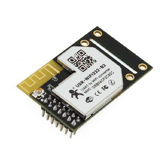
Summary of Contents for USR IOT USR-WIFI232-B2
-
Page 1: Usr-Wifi232-B2 Hardware Manual
USR-WIFI232-B2 Hardware Manual www.usriot.com USR-WIFI232-B2 Hardware Manual File version: 1.0.0 Jinan USR IOT Technology Limited 1 / 9 h.usriot.com... -
Page 2: Table Of Contents
USR-WIFI232-B2 Hardware Manual www.usriot.com Content USR-WIFI232-B2 Hardware Manual ................... 1 1. Product Overview ........................3 1.1. Dimension ........................3 1.2. Encapsulation ........................ 3 1.3. Pin Defination ........................ 4 2. Hardware Design ........................5 2.1. Typical Connection ......................5 2.2. Power Interface......................5 2.3. -
Page 3: Product Overview
USR-WIFI232-B2 Hardware Manual www.usriot.com 1. Product Overview 1.1. Dimension Module dimension diagram as follows: 1.2. Encapsulation You can download PCB library from http://www.usriot.com/pcb-library-usr-wifi232-a2b2-pcb-library-file/ Jinan USR IOT Technology Limited 3 / 9 h.usriot.com... -
Page 4: Pin Defination
GPIO9 Can be configured as GPIO. nReload Take effect in low level. Press over 3s restore factory settings. GPIO10 PHY_RX+ Ethernet Input+ PHY_RX- Ethernet Input- PHY_TX+ Ethernet Output+ PHY_TX- Ethernet Output- Jinan USR IOT Technology Limited 4 / 9 h.usriot.com... -
Page 5: Hardware Design
2.1. Typical Connection 2.2. Power Interface USR-WIFI232-B2 adopt single-voltage 3.3 V power supply. Peak current is about 350mA, work current is about 200mA and sleep mode current is 100mA. The power filter is recommended to be used near the connector of the user board, and it is recommended to use two parallel decoupling capacitors with 100uF and 10uF to improve the stability of the system and wireless performance. -
Page 6: 10/100M Ethernet Interface
2.4. 10/100M Ethernet Interface 2.4.1.Ethernet Interface with Transformer Put the Ethernet transformer and RJ45 connector on the circuit board can get the standard 10/100M Ethernet interface.The reference circuit diagram as follows: Jinan USR IOT Technology Limited 6 / 9 h.usriot.com... -
Page 7: Ethernet Interface Without Transformer
Note: VCC signal at reference design shall base on user board PHY chipset voltage level, such as 2.5V power supply for general Ethernet PHY chipset. USR-WIFI232-B2 Ethernet interface default is for the application with transformer connection. If user need PHY-PHY directly connection, please refer to above diagram and use follows AT commands:... -
Page 8: Reset And Reload
3.3V and no need to connect to external pull-up resistor. 2.6. Antenna USR-WIFI232-B2 adpot external antenna and USR-WIFI232-B2 need connect to the 2.4GHz antenna that conforms to 802.11b/g/n.The specific parameters of the antenna as the following table: Jinan USR IOT Technology Limited 8 / 9 h.usriot.com... -
Page 9: Contact
4. Disclaimer This document provide the information of USR-WIFI232-B2 products, it hasn’t been granted any intellectual property license by forbidding speak or other ways either explicitly or implicitly. Except the duty declared in sales terms and conditions, we don’t take any other responsibilities. We don’t warrant the products sales and use explicitly or implicitly, including particular purpose merchantability and marketability, the tort liability of any other patent right, copyright, intellectual property right.


Need help?
Do you have a question about the USR-WIFI232-B2 and is the answer not in the manual?
Questions and answers