Table of Contents
Advertisement
Advertisement
Table of Contents
Troubleshooting

Related Manuals for Sailor 624228 VHF DSC


Summary of Contents for Sailor 624228 VHF DSC
- Page 1 INSTALLATION MANUAL SAILOR 6248 VHF SAILOR 6222 VHF DSC...
- Page 3 SAILOR 6222 VHF DSC Installation manual Document number: 98-132904-C Release date: October 11, 2011...
- Page 4 © 2011 Thrane & Thrane A/S. All rights reserved. Trademark Acknowledgements • SAILOR is a registered trademarks of Thrane & Thrane A/S. • Other product and company names mentioned in this manual may be trademarks or trade names of their respective owners.
- Page 5 Thrane & Thrane assumes no liability for the customer's failure to comply with these requirements. Ground the equipment To minimise shock hazard, the SAILOR 6222 VHF DSC unit must be connected to an electrical ground and the cable instructions must be followed. RF exposure hazards and instructions Your Thrane &...
-
Page 6: Record Of Revisions
SAILOR 6222 VHF DSC is designed for installation by a skilled service person. Training information The SAILOR 6222 VHF DSC is designed for occupational use only and is also classified as such. It must be operated by licensed personnel only. It must only be used in the course of employment by individuals aware of both the hazards as well as the way to minimize those hazards The radio is thus NOT intended for use in an uncontrolled environment by general public. - Page 7 regarding RF energy and electromagnetic energy levels including the recommended levels for human exposure: • FCC OET Bulletin 65 Supplement C, evaluating compliance with FCC guidelines for human exposure to radio frequency electromagnetic fields. • American National Standards Institute (C95.1) IEEE standard for safety levels with respect to human exposure to radio frequency electromagnetic fields, 3 kHz to 300 GHz •...
-
Page 8: Related Documents
Table Preface-1: Related documents Online training for Thrane partners As a Thrane Partner you have access to free of charge technical training in this SAILOR product covering installation, commissioning and repair. For details on available training classes please consult the Thrane Academy at http://extranet.thrane.com/Training.aspx. -
Page 9: Table Of Contents
Troubleshooting guide ..............4-3 Warranty and returning units for repair ..........4-9 Appendix A Technical specifications Transceiver unit SAILOR 6222 VHF DSC ..........A-1 General DSC specifications ............... A-3 NMEA data rates and formats ............A-4 SAILOR 6090 Power Converter 24—12 V ........... A-4... - Page 10 Table of contents Index ......................... Index-1 viii 98-132904-C...
- Page 11 SAILOR 6207 Connection Box for parallel handsets, diagram......2-23 Figure 2-18: SAILOR 6208 Control Unit Connection Box, mounting .........2-24 Figure 2-19: SAILOR 6208 Control Unit Connection Box for parallel handsets, wiring .....2-24 Figure 2-20: SAILOR 6208 Control Unit Connection Box, diagram ...........2-25 Figure 4-1: Fuse in the power connector ................4-7...
- Page 12 System configuration, CAN bus, SAILOR 6204 CSM, close to the VHF radio..B-13 Figure B-12: System configuration, CAN bus, SAILOR 6204 CSM, not close to the VHF radio... B-14 Figure B-13: System configuration, CAN bus, SAILOR 6204 CSM, far from the VHF radio ..B-15 Figure B-14: System configuration, CAN bus, 2 SAILOR 6204 CSMs, close to VHF radio ..
- Page 13 Technical specifications, part 2................A-2 Table A-3: DSC specifications ....................A-3 Table A-4: NMEA data rates and formats ................A-4 Table A-5: Technical specifications, SAILOR 6090..............A-4 Table B-1: Cable overview ....................B-28 Table B-2: Cable specifications for cable 2................B-30 Table B-3: Cable specifications for cable 3................
- Page 14 List of tables 98-132904-C...
-
Page 15: Chapter 1 Introduction
With SAILOR connection boxes the VHF radio connects easily to external equipment like additional handsets, water proof hand microphones, control speaker microphone, alarm panel or external speaker. The Ethernet interface enables the VHF radio to be connected to ThraneLINK for service updates. -
Page 16: Figure 1-1: Controls On The Front Plate
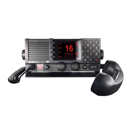
VHF radio with DSC Class A 1.1.1 Controls on the front plate Figure 1-1: Controls on the front plate 1. Loudspeaker. 2. Four soft keys with function title in the display. 3. Large display. 4. Keys 0 to 9 to enter numbers or text. 5. - Page 17 VHF radio with DSC Class A 1.1.2 SAILOR 6222 VHF DSC display The picture shows the display after start-up. The display holds various fields of information, depending on the currently selected function. CALL 1. Functions you can select with the soft keys. If...
-
Page 18: Accessories Available
Box including Connection Cable Connection Box 406208-941 is used for easy installation of external equipment and accessories: • Max. 4 SAILOR 6204 Control Speaker Microphones • VDR • SAILOR 6270 External loudspeaker • Alarm panels and GPS input Table 1-1: Accessories available... - Page 19 SAILOR 6201 or 6203 Handset is not connected directly to the SAILOR 6222 VHF DSC, but located in a different position (part number: 406204-940). 5m Connection cable, 1x10 pole: Use this cable in installations when connecting external equipment to the SAILOR 6222 VHF DSC.
-
Page 20: Figure 1-2: System Configuration, Example
Accessories available 1.2.1 System configuration — example The SAILOR 6222 VHF DSC can be customized to suit your installation. The following illustration is one example of a system. For further configuration examples see Appendix B, System configurations. RX/DSC RX/TX Aerial... -
Page 21: Chapter 2 Installation
• VHF and DSC antenna installation • Accessories Unpacking and initial inspection The following items are included in the delivery of a SAILOR 6222 VHF DSC: • SAILOR 6222 VHF DSC • SAILOR 6201 Handset with cradle • User manual •... -
Page 22: Installing The Vhf Radio
Provide space enough to access the front panel connectors and for installing a cradle for the speaking device. Provide at least 120 mm space at the back of the SAILOR 6222 VHF DSC radio to allow free air circulation and for cable access. -
Page 23: Table 2-1: Compass Safe Distance
SAILOR 6222 VHF DSC 0.85 m SAILOR 6201 and 6203 Handset with cradle 0.95 m SAILOR 6090 Power Converter 24 V — 12 V 0.15 m SAILOR 6207 Connection Box for parallel handsets 0.45 m SAILOR 6208 Control Unit Connection Box 0.45 m... -
Page 24: Figure 2-2: Overhead Mounting
Installing the VHF radio Overhead mounting Figure 2-2: Overhead mounting Mounting with U mounting bracket To mount the VHF radio as tabletop, do as follows: 1. Find a suitable location for the VHF radio. Check that the space is wide/deep enough to accommodate the VHF radio. -
Page 25: Figure 2-3: Mounting With The Mounting Bracket
Installing the VHF radio 4. The display of the VHF radio should be at an angle of approximately 90° to your line of sight when operating it. Figure 2-3: Mounting with the mounting bracket 4 x M4 or hole for self-tapping ø3.9 23.5mm 200mm... -
Page 26: Figure 2-5: Sailor 6222 Vhf Dsc Dimension For Flush Mount
You can mount the VHF radio to a flat surface, e.g. an instrument panel. The flush mount installation kit is included in the delivery. Figure 2-5: SAILOR 6222 VHF DSC Dimension for flush mount R2.5mm x 4 Flush mount template... -
Page 27: Figure 2-7: Flush Mount
Installing the VHF radio 5. Ensure that the flush mount gasket is placed correctly on the VHF radio. 6. Before mounting the VHF radio be aware that the surface is plane and rigid. If the surface is not plane and/or rigid (stiff) remove the gasket and seal with silicone sealant between the VHF radio and the surface. -
Page 28: Figure 2-8: Sailor 6090 Power Converter, Dimensions
Installing the VHF radio 2.2.3 SAILOR 6090 Power Converter Figure 2-8: SAILOR 6090 Power Converter, dimensions Remove jumper for remote on/off from VHF Ground 24V DC 12V DC 99-132778 Figure 2-9: Connecting the SAILOR 6090 Power Converter Chapter 2: Installation 98-132904-C... -
Page 29: Figure 2-10: Sailor 6201 Handset With Cradle
The cradle must be installed as illustrated in order to ensure the hook-on/off functionality of the Handset. 39655C Figure 2-10: SAILOR 6201 Handset with cradle 98-132904-C Chapter 2: Installation... -
Page 30: Connectors
2.3.1 Connector at the front panel for handset or handmicrophone Use the connector at the front of the SAILOR 6222 VHF DSC to connect a SAILOR 6201 Handset. You may also connect a waterproof SAILOR 6203 Handset or SAILOR 6202 Handmicrophone. -
Page 31: Figure 2-11: Connections At The Rear Panel
Connectors 2.3.2 Connectors at the rear panel Figure 2-11: Connections at the rear panel 1. ACC connector for accessories 2. AUX connector for VDR, external speaker, alarm panels, GPS input 3. Power connector PWR FUSE with fuse 10 A mini ATO 4. -
Page 32: Table 2-3: Pin Allocation, Acc Connector
Connectors 2.3.3 ACC connector Use the connector marked ACC to connect GPS and a SAILOR 6201 Handset. You may also connect a waterproof SAILOR 6203 Handset or SAILOR 6202 Handmicrophone. Connector type: Circular connector, 10pin, male. Panel lock, 10 pin male Connection cable with plug, part number 406209-941. -
Page 33: Figure 2-12: Nmea Interface Description
Connectors NMEA interface description connector pin1 O pin2 O NMEA in+ pin3 O 500R NMEA in- pin4 O NMEA in+ pin1 O NMEA in- pin2 O NMEA-HS in- pin3 O NMEA-HS in+ pin4 O 500R connector Figure 2-12: NMEA interface description NMEA input: Impedance: 600 Ohm. -
Page 34: Table 2-4: Pin Allocation, Aux Connector
Connectors 2.3.4 AUX connector This connector is used to connect VDR, external speaker, DSC alarms and GPS input. Connector type: Circular connector, 12pin. Connection cable with plug, part number 406208-941. Pin assignment: Connector front view on the VHF radio: Description Wire color Shield (GND) Brown... -
Page 35: Table 2-5: Pin Allocation, Ctrl Connector
Connectors 2.3.5 CTRL connector This connector is used to connect a SAILOR 6204 Control Speaker Microphone or SAILOR 6208 Connection Box. Connector type: Circular connector, 12pin. Connection cable with plug, part number 406208-941. Pin assignment: Connector front view on the VHF radio:... -
Page 36: Table 2-6: Pin Allocation, Lan Connector
To help extract the fuse you can order a fuse puller in the ESHOP at http://extranet.thrane.com/. Pin-out The figure and table below show the connector outline, pin assignments and wire color in the power cable delivered with the SAILOR 6222 VHF DSC. Pin function Wire color DC+ (10.8 - 15,6 V DC) - Page 37 Important The ground stud is located on the rear panel and is used to connect a ground wire for grounding the SAILOR 6222 VHF DSC. To connect the SAILOR 6222 VHF DSC to ship ground, do as follows: 1. Connect a ground cable of > 1 m length and > 4 mm...
-
Page 38: Vhf And Dsc Antenna Installation
VHF and DSC antenna installation VHF and DSC antenna installation The SAILOR 6222 VHF DSC must be installed with one antenna for VHF RX/TX communication and one antenna for DSC communication. You can install all commonly available 50 Ohm antennas covering the appropriate frequency range and providing a VSWR less than 1.5 over this range. -
Page 39: Figure 2-13: Antenna Positioning 1/2
VHF and DSC antenna installation antennas as far away as possible from antenna main beam of any radar and satellite equipment. No. 1 VHF No. 2 VHF RX/TX No. 2 VHF No. 1 VHF RX/TX 39679 Figure 2-13: Antenna positioning 1/2 Figure 2-14: Antenna positioning, 2/2 2.4.3 DSC antenna... -
Page 40: Accessories
Table 2-8: Part numbers for accessories You can connect a LAN printer to the radio for printing DSC messages, see also Setup of a LAN printer to work with SAILOR 6222 VHF DSC on page 2-25. 2-20 Chapter 2: Installation... -
Page 41: Figure 2-15: Sailor 6207 Connection Box For Parallel Handsets, Mounting
2.5.2 Connection box SAILOR 6207 The SAILOR 6207 Connection Box is used to connect GPS (NMEA), GPS/AIS DSC modem and further SAILOR 6201 Handsets. For wiring and cabling details see System configuration examples on page B-1 and How to install LAN on page B-25. -
Page 42: Figure 2-17: Sailor 6207 Connection Box For Parallel Handsets, Diagram
-VBAT > > , E ^ d & & -VBAT -VBAT > > ,KK< Wdd & & > > -VBAT -VBAT & & -VBAT -VBAT Figure 2-17: SAILOR 6207 Connection Box for parallel handsets, diagram 2-22 Chapter 2: Installation 98-132904-C... -
Page 43: Figure 2-18: Sailor 6208 Control Unit Connection Box, Mounting
2.5.3 Connection box SAILOR 6208 The SAILOR 6208 Connection Box is used to connect SAILOR 6204 Control Speaker microphones and other auxiliary equipment. For wiring and cabling details see System configuration examples on page B-1 and How to install LAN on page B-25. -
Page 44: Figure 2-20: Sailor 6208 Control Unit Connection Box, Diagram
Accessories Terminate the last SAILOR 6208 on the CAN bus (furthest away from the transceiver). Figure 2-20: SAILOR 6208 Control Unit Connection Box, diagram 2-24 Chapter 2: Installation 98-132904-C... - Page 45 If a single printer is connected to the SAILOR 6222 VHF DSC LAN connector, you must activate it: 1. Switch on the SAILOR 6222 VHF DSC and use the soft key MORE until SETUP is displayed. 2. Press SETUP and use the arrow keys to advance to DSC Setup.
- Page 46 Accessories 2-26 Chapter 2: Installation 98-132904-C...
-
Page 47: Chapter 3 First-Time Power Up
First-time power up General use and navigation The tasks needed to be performed during installation are described below. See the SAILOR 6222 VHF DSC User manual for instructions how to operate and set up the VHF radio. 3.1.1 Power on and volume in handset and speaker The VHF radio has a dual-function on/off knob for power on/off and volume control. -
Page 48: Entering The Mmsi Number
3.2.2 Changing the MMSI number If you need to change the MMSI number of the SAILOR 6222 VHF DSC use the built-in service tool and a connected PC, or reset the MMSI number from the Setup menu of the radio. The manuals for the service tool and the user manual for the radio can be downloaded from http://extranet.thrane.com. -
Page 49: Chapter 4 Service & Maintenance
4.2.1 Preventive maintenance Maintenance of the SAILOR 6222 VHF DSC can be reduced to a maintenance check at each visit of the service staff. Inspect the radio for mechanical damages, salt deposits, corrosion and any foreign material. Due to its robust construction and ruggedness the radio has a long lifetime. - Page 50 Maintenance without enabling the transmitter power amplifier. In parallel the radio decodes and compares the received call to be the same as the transmitted. The display shows the result of the test. TEST RESULT TEST RESULT 4. Press the soft key OK to acknowledge the test DSC loopback DSC loopback test passed...
-
Page 51: Troubleshooting Guide
Troubleshooting guide Troubleshooting guide Action Symptom Remedy The radio The display Check if power is present. will not is empty. Check fuse which is placed in the power turn on connector. Check performance of power supply if connected to one. The loud- Check the antenna installation. -
Page 52: Table 4-1: Troubleshooting Guide
Troubleshooting guide Action Symptom Remedy Check the DSC function regularly. Verify the routine complete DSC installation, with antennas, by testing transmitting a Safety Test call to another station (coast or ship). The test call is generated using the DSC call flow via menu CALL. - Page 53 SUPPLY status You can only monitor the power supply if the LOST cannot be radio is powered by a SAILOR 6081 Power CONTACT monitored. Supply Unit and Charger. Table 4-1: Troubleshooting guide 98-132904-C Chapter 4: Service & maintenance...
-
Page 54: Figure 4-1: Fuse In The Power Connector
Troubleshooting guide 4.3.1 Replacing the fuse in the power connector One fuse is installed in the power connector. If the fuse is blown, do as follows: 1. Track down why the fuse was blown and solve the problem. 2. Take out the old fuse. 3. -
Page 55: Figure 4-2: Fuse In The Sailor 6090 Power Converter
4.3.2 Replacing the fuse in the SAILOR 6090 Power Converter One fuse is installed in the SAILOR 6090 Power Converter. If the fuse is blown, do as follows: 1. Track down why the fuse was blown and solve the problem. -
Page 56: Warranty And Returning Units For Repair
Should you need to send the product for repair, please read the below information before packing the product. The shipping carton has been carefully designed to protect the SAILOR 6222 VHF DSC and its accessories during shipment. This carton and its associated packing material should be used when repacking for shipment. -
Page 57: Appendix A Technical Specifications
< 1.50 kg (3.3 lbs) approximately Box weight 3.8 kg (8.4 lbs) approximately, including SAILOR 6222 VHF DSC SAILOR 6201 Handset and wall mount cradle, SAILOR 6090 Power Converter and Installation and user manual in box. Dimensions Height: Outer dimension 107 mm, hole... -
Page 58: Table A-2: Technical Specifications, Part 2
Transceiver unit SAILOR 6222 VHF DSC Item Specification Frequency range TX: 156,000 MHz — 157,425 MHz, RX: 156,000 MHz — 163.425 MHz Channel spacing 12.5 kHz and 25 kHz, all international maritime channels Number of P channels The radio may be programmed with up to 100 private channels in all channel modes. -
Page 59: General Dsc Specifications
General DSC specifications Item Specification LF power Built-in loudspeaker: 6 W (at 5 kHz dev./1 kHz tone) External loudspeaker: 6 W / 8 Ohm Distortion Below 5% S/N ratio Better than 43 dB Spurious emissions Below 2 nW Spurious response More than 74 dB rejection Intermodulation response... -
Page 60: Nmea Data Rates And Formats
NMEA data rates and formats NMEA data rates and formats Item Value 61162-1 4800,8,n,1 61162-2 38400,8,n,1 Table A-4: NMEA data rates and formats SAILOR 6090 Power Converter 24—12 V Item Description Weight 300 g Dimensions Height: 33 mm Width: 190 mm Depth: 85 mm Operating temperature -25°C to 55°C (5°F to 131°F) -
Page 61: Appendix B System Configurations
16. How to install a CAN bus with 2 SAILOR 6204 CSMs close to each other 17. How to install a CAN bus with 2 SAILOR 6204 CSMs close to VHF on a small bridge 18. How to install a CAN bus with 2 CSMs in bridge wings... -
Page 62: System Configuration Examples
System configuration examples 19. How to install a CAN bus with 4 SAILOR 6204 CSMs 20.How to install a CAN bus with 4 CSMs in bridge wings 21. How to install a CAN bus with 3 SAILOR 6204 CSMs 22.How to install a CAN bus with 4 SAILOR 6204 CSMs 23. -
Page 63: Figure B-1: System Configuration, Sailor 6090 Power Converter
System configuration examples B.1.1 How to connect a SAILOR 6090 Power Converter RX/TX DSC/RX SAILOR 6201 /03 SAILOR 6222 VHF DSC Remove jumper for remote on/off from VHF Remote on/off (Yellow) 12VDC -Vout (Blue) +Vout (Red) Ground 24VDC Screen/ground -Vin... -
Page 64: Figure B-2: System Configuration, Sailor N163S Power Supply
System configuration examples B.1.2 How to connect a SAILOR N163S AC Power Supply RX/TX DSC/RX SAILOR 6222 SAILOR 6201 /03 VHF DSC 12VDC Alarm connection for AC failure 24VDC to SAILOR 6090 24VDC 24VDC from Battery Earth/ground SAILOR N163S Power Supply... -
Page 65: Figure B-3: System Configuration, Sailor 6201 Handset And N420 Dc Power Supply
How to connect an N420 DC Power Supply RX/TX DSC/RX SAILOR 6201/03 SAILOR 6222 VHF DSC 12VDC 12VDC Output On/off 24VDC Input 24VDC Figure B-3: System configuration, SAILOR 6201 Handset and N420 DC Power Supply 98-132904-C Appendix B: System configurations... -
Page 66: Figure B-4: System Configuration, Sailor 6201, Gps, Ext. Loudspeaker And Alarms
System configuration examples B.1.4 How to install an extra SAILOR 6201, GPS, ext. loudspeaker and alarms Brown Shield Blue Lo pwr forced control White NMEA In+ Green NMEA In- Yellow AUX alarm Grey DSC Call RX/TX DSC/RX Pink DSC Alarm... -
Page 67: Figure B-5: System Configuration, Gps And Sailor 6270 External Loudspeaker
System configuration examples B.1.5 How to install a GPS and SAILOR 6270 External loudspeaker White NMEA In + Green NMEA In - RX/TX DSC/RX Black Ext. Speaker+ Orange Ext. Speaker - SAILOR 6201 /03 SAILOR 6222 VHF DSC Connection box... -
Page 68: Figure B-6: System Configurations, 2 Sailor 6201 Handsets And A Gps
System configuration examples B.1.6 How to install 2 extra SAILOR 6201 Handsets and a GPS RX/TX DSC/RX Cable 6 may be extended to max 100m. SAILOR SAILOR SAILOR 6201 /03 6201 /03 6201 /03 SAILOR 6207 SAILOR 6222 Connection box... -
Page 69: Figure B-7: System Configurations, Extra Handset Sailor 6201 In Sailor 6207
System configuration examples B.1.7 How to install an extra Handset SAILOR 6201 in SAILOR 6207 RX/TX DSC/RX Cable 6 may be extended to max 100m. SAILOR SAILOR 6201 /03 SAILOR 6222 6201 /03 SAILOR 6207 VHF DSC Connection box 12VDC... -
Page 70: Figure B-8: System Configuration, Sailor 6202 Handmic., Sailor 6201 Handset, Gps
SAILOR 6201/03 SAILOR 6202 SAILOR 6222 VHF DSC Connection box SAILOR 6207 12VDC NMEA 24VDC receiver SAILOR N163 S Power Supply 3/25/2011 24VDC 110VAC/230VAC Figure B-8: System configuration, SAILOR 6202 Handmic., SAILOR 6201 Handset, GPS B-10 Appendix B: System configurations 98-132904-C... -
Page 71: Figure B-9: System Configuration, Gps And Sailor 6208 Connection Box
System configuration examples B.1.9 How to install a GPS to the ACC port with a SAILOR 6208 Connection Box Remove jumper NMEA In + Brown NMEA In - Blue White NMEA In - HS Green NMEA In + HS Yellow... -
Page 72: Figure B-10: System Configuration, Gps And Sailor 6207 Connection Box
System configuration examples B.1.10 How to install a GPS to the ACC port using a SAILOR 6207 Connection Box SAILOR 6207 Connection box receiver RX/TX DSC/RX 1/17/2011 NMEA SAILOR 6201/03 SAILOR 6222 VHF DSC NMEA+ Brown NMEA- Blue NMEA- HS... -
Page 73: Figure B-11: System Configuration, Can Bus, Sailor 6204 Csm, Close To The Vhf Radio
System configuration examples B.1.11 How to install a CAN bus with a SAILOR 6204 CSM close to the VHF radio SAILOR 6204 Control Speaker Microphone (without DSC) RX/TX DSC/RX SAILOR 6201 /03 SAILOR 6222 VHF DSC 12VDC CTRL 24VDC SAILOR N163S... -
Page 74: Figure B-12: System Configuration, Can Bus, Sailor 6204 Csm, Not Close To The Vhf Radio
System configuration examples B.1.12 How to install a CAN bus with a SAILOR 6204 CSM not close to the VHF radio SAILOR 6204 Control Speaker Microphone (without DSC) RX/TX DSC/RX SAILOR 6201 /03 SAILOR 6208 Connection box SAILOR 6222 VHF DSC... -
Page 75: Figure B-13: System Configuration, Can Bus, Sailor 6204 Csm, Far From The Vhf Radio
System configuration examples B.1.13 How to install a CAN bus with a SAILOR 6204 CSM far from the VHF radio SAILOR 6204 Control Speaker Microphone RX/TX DSC/RX (without DSC) SAILOR 6201 /03 SAILOR 6208 SAILOR 6208 Connection box Connection box... -
Page 76: Figure B-14: System Configuration, Can Bus, 2 Sailor 6204 Csms, Close To Vhf Radio
System configuration examples B.1.14 How to install a CAN bus with 2 SAILOR 6204 CSMs close to the VHF radio SAILOR 6204 SAILOR 6204 Control Control Speaker Microphone Speaker Microphone (without DSC) (without DSC) RX/TX DSC/RX SAILOR 6201 /03 SAILOR 6208... -
Page 77: Figure B-15: System Configuration: Can Bus, 2 Sailor 6204 Csms, Far From Vhf Radio
System configuration examples B.1.15 How to install a CAN bus with 2 SAILOR 6204 CSMs far from the VHF radio SAILOR 6204 SAILOR 6204 Customer supplied terminals for Control Control resizing/extension of supply wires Speaker Microphone Speaker Microphone (without DSC) -
Page 78: Figure B-16: System Configuration: Can Bus, 2 Sailor 6204 Csms, Close To Each Other
System configuration examples B.1.16 How to install a CAN bus with 2 SAILOR 6204 CSMs close to each other SAILOR 6204 SAILOR 6204 Control Control Speaker Microphone Speaker Microphone RX/TX DSC/RX (without DSC) (without DSC) SAILOR 6201/03 SAILOR 6208 SAILOR 6208... -
Page 79: Figure B-17: System Configuration: Can Bus, 2 Sailor 6204 Csms, Close Vhf, Small Bridge
System configuration examples B.1.17 How to install a CAN bus with 2 SAILOR 6204 CSMs close to VHF on a small bridge SAILOR 6204 SAILOR 6204 Control Control Speaker Microphone Speaker Microphone RX/TX DSC/RX (without DSC) (without DSC) SAILOR 6201 /03... -
Page 80: Figure B-18: System Configuration: Can Bus, 2 Sailor 6204 Csms, In Bridge Wings
RX- telephony out RX- telephony out Violet Violet TX+ telephony in TX+ telephony in Cyan TX- telephony in Cyan TX- telephony in Figure B-18: System configuration: CAN bus, 2 SAILOR 6204 CSMs, in bridge wings B-20 Appendix B: System configurations 98-132904-C... -
Page 81: Figure B-19: System Configuration: Can Bus, 3 Sailor 6204 Csms, In Bridge Wings
TX+ telephony in Violet TX+ telephony in Cyan TX- telephony in TX- telephony in Cyan Costumer supplied terminals for resizing/extension of supply wires Figure B-19: System configuration: CAN bus, 3 SAILOR 6204 CSMs, in bridge wings 98-132904-C Appendix B: System configurations B-21... -
Page 82: Figure B-20: System Configuration: Can Bus, 4 Sailor 6204 Csms, In Bridge Wings
TX+ telephony in Violet TX+ telephony in Cyan TX- telephony in TX- telephony in Cyan Costumer supplied terminals for resizing/extension of supply wires Figure B-20: System configuration: CAN bus, 4 SAILOR 6204 CSMs, in bridge wings B-22 Appendix B: System configurations 98-132904-C... -
Page 83: Figure B-21: System Configuration: Can Bus, 3 Sailor 6204 Csms
System configuration examples B.1.21 How to install a CAN bus with 3 SAILOR 6204 CSMs SAILOR 6204 Note! Control Maximum total length of all cable 16 must not exceed 100m! Speaker Microphone SAILOR 6208 (without DSC) Connection box Place jumper for termination... -
Page 84: Figure B-22: System Configuration: Can Bus, 4 Sailor 6204 Csms
System configuration examples B.1.22 How to install a CAN bus with 4 SAILOR 6204 CSMs SAILOR 6204 Control Note! Speaker Microphone SAILOR 6208 Maximum total length of all cable 16 must not exceed 100 m! (without DSC) Connection box Place jumper for termination... -
Page 85: Figure B-23: System Configuration: Installation Of Lan
System configuration examples B.1.23 How to install LAN SAILOR 6103 Alarm Panel RX/TX DSC/RX Cable 6 may be extended up to max 100m. SAILOR SAILOR 6201 /03 SAILOR 6222 6201 /03 SAILOR 6207 VHF DSC Connection box 12VDC NMEA NMEA+... -
Page 86: Figure B-24: System Configuration: Installation Of A Printer
System configuration examples B.1.24 How to install a printer RX/TX DSC/RX Printer Server 9/27/2011 9/27/2011 SAILOR 6201 /03 SAILOR 6222 VHF DSC 12VDC 24VDC SAILOR N163S Power Supply 110VAC/230VAC 24VDC Figure B-24: System configuration: Installation of a printer B-26 Appendix B: System configurations... -
Page 87: Figure B-25: System Configuration: Installation Of An Additional Printer
System configuration examples B.1.25 How to install an additional printer RX/TX DSC/RX Printer Server 9/27/2011 9/27/2011 SAILOR 6201 /03 SAILOR 6222 VHF DSC Printer Server 9/27/2011 12VDC 9/27/2011 24VDC SAILOR N163S Power Supply 110VAC/230VAC 24VDC Figure B-25: System configuration: Installation of an additional printer... -
Page 88: Cable Requirements
Not a T&T 3-wire power cable, Depends on length 24 VDC, 4 A part shielded 406209-941 5 m cable for SAILOR 10-pole LTW cable with Included in Connection 6207 Connection Box screen Box 406207A 406209-940 5 m cable for bulk mount... - Page 89 0.5 mm max. 5 m Not a T&T Extension cable for 4 leads, screened wires See cable description. part power supply for SAILOR of 4 mm depending on 6204. the current and/or cable length. Not a T&T USB 2.0 cable...
-
Page 90: Table B-2: Cable Specifications For Cable 2
Cable requirements Cable 2 (Handset, cable included) SAILOR 6222 VHF DSC Front Signal connector Signal description designation LTW 10-pin, circular male Pin 1 Pin 2 Pin 3 Pin 4 Pin 5 MIC+ Microphone signal Pin 6 Earpiece Earpiece signal Pin 7... -
Page 91: Table B-4: Cable Specifications For Cable 5
Cable requirements Cable 4 (Power cable) Cable type: 3-wire screened cable. Dimensions depend on the cable length. Cable 5 (Cable for SAILOR 6207 Connection Box) Cable type: 10-wire screened cable. Part number: 406209-941 The cable screen must not touch any metal part of the connection box due to galvanic separation. -
Page 92: Table B-5: Cable Specifications For Cable 8 (Aux
Connection cable for bulkhead mount, 5 m. Part number: 406209-940 Same pin configuration as cable 5. Cable 7 2-wire screened cable for NMEA (GPS connection). Cable 8 (AUX) Part number: 406208-941 SAILOR 6222 Cable SAILOR SAILOR SAILOR VHF DSC Ships cable... - Page 93 Cable requirements SAILOR 6222 Cable SAILOR SAILOR SAILOR VHF DSC Ships cable 6208 6208 6208 Signal 6 twisted 406208- Conn. Box Conn. Box Conn. Box Signal description connector designation pairs In from Out of Out of LTW 12-pin, overall screen...
-
Page 94: Table B-6: Cable Specifications For Cable 8 (Ctrl
Cable requirements CAN cable (Cable 8 - CTRL) Part number: 406208-941 SAILOR 6222 Cable SAILOR SAILOR SAILOR VHF DSC Ships cable 6208 6208 6208 CTRL Signal 6 twisted 406208- Conn. Box Conn. Box Conn. Box Signal description connector designation pairs... -
Page 95: Table B-7: Pin Allocation, Lan Connector
Cable requirements Cable 11 LAN connection. Ethernet cable with screen and RJ45 shielded plugs. Pin number Pin function Wire color white/orange orange white/green Not connected blue Not connected white/blue green Not connected white/brown Not connected brown Table B-7: Pin allocation, LAN connector Cable 16 The CAN bus cable must be of a paired and twisted type designed for the purpose. - Page 96 Cable requirements Cable 17: CAN cable for bulk head installation. Same cable as cable 12, but the plug is removed and the wires are connected to the connection box. Same pin configuration as cable 8. See Cable specifications for cable 8 (CTRL) on page B-34.
-
Page 97: Glossary
Glossary Glossary Accessories Controller-Area Network. A message based protocol designed to allow microcontrollers and devices to communicate with each other within a vehicle without a host computer. Control Speaker Microphone CTRL Control Digital Selective Calling NMEA sentence, essential fix data which provide 3D location and accuracy data. NMEA sentence, Geographic Latitude and Longitude NMEA sentence, Global Positioning System... - Page 98 Glossary NMEA National Marine Electronics Association, specification for communication between marine electronic devices NMEA sentence, version of essential gps position, velocity, time data. Universal Serial Bus. A specification to establish communication between devices and a host controller (usually personal computers). USB is intended to replace many varieties of serial and parallel ports.
- Page 99 Index Index contact, 4-1 controls, front plate, 1-2 AC power supply cradle for 6201, installation, 1-4 connect, B-4 CTRL connector, 2-15, 2-16 ACC connector, 2-13 action line, display, 1-3 adjust speaker volume, 3-1 ANT connector, 2-18 data rate NMEA, A-4 DC power supply connect, B-5 delivery, items included, 2-1...
- Page 100 Index handset cradle installation, 1-4 NMEA, 2-13 how to replace, 4-8 data rate, A-4 interface, 2-14 NMEA HS, 2-13 input GPS, 2-22 handset, 2-22 power installation fuse, 4-7 cradle for 6201, 1-4 off, 3-1 desktop, 2-3 on, 3-1 flush mount, 2-6 power cable, B-31 handset cradle, 1-4 Power Converter...
- Page 101 Index specifications, A-1 squelch control, 1-2 support, 4-1 system configuration example, 1-6 technical data, A-1 temperature operational, A-1, A-4 storage, A-1, A-4 UTC time, 1-3 antenna cable, 2-18 antenna connector, 2-18 frequency range, A-2 volume louder, 3-1 softer, 3-1 speaker, 3-1 Volume knob, 1-2 warnings, 4-1 warranty, 4-9...
- Page 102 Index Index-4 98-132904-C...
- Page 104 98-132904-C info@thrane.com thrane.com •...
Need help?
Do you have a question about the 624228 VHF DSC and is the answer not in the manual?
Questions and answers