
Related Manuals for Airwell K DCI Series


Summary of Contents for Airwell K DCI Series
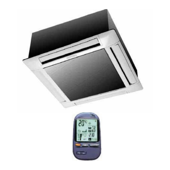
- Page 1 Service Manual K DCI Inverter series Indoor Units Outdoor Units K 9 DCI INV GC9 DCI INV K 12 DCI INV GC12 DCI INV K 18 DCI INV GC18 DCI INV REFRIGERANT R410A HEAT PUMP TM KDCI-A-1-GB DECEMBER 2004...
- Page 2 LIST OF EFFECTIVE PAGES LIST OF EFFECTIVE PAGES Note: Changes in the pages are indicated by a “Revision#” in the footer of each effected page (when none indicates no changes in the relevant page). All pages in the following list represent effected/ non effected pages divided by chapters.
-
Page 3: Table Of Contents
TABLE OF CONTENTS Table of Contents INTRODUCTION ....................1-1 PRODUCT DATA SHEET ..................2-1 RATING CONDITIONS ..................3-1 OUTLINE DIMENSIONS ..................4-1 PERFORMANCE DATA ..................5-1 PRESSURE CURVES ...................6-1 ELECTRICAL DATA ....................7-1 WIRING DIAGRAMS .....................8-1 REFRIGERATION DIAGRAMS ................9-1 10. TUBING CONNECTIONS ..................10-1 11. CONTROL SYSTEM .....................11-1 12. -
Page 4: Introduction
INTRODUCTION INTRODUCTION General The new K DCI INVERTERS split Cassette range comprise the following RC (heat pump) models: K 9 DCI INV • K 12 DCI INV • K 18 DCI INV • The New DCI K units can be easily fitted to residential and commercial applications featuring esthetic design, compact dimensions, and low noise operation. - Page 5 INTRODUCTION Filtration The K DCI INV series presents several types of air filters: Easily accessible, and re-usable pre-filters (mesh) • Pre-charged electrostatic filter (disposable) • Active carbon filter (disposable) • Control The microprocessor indoor and outdoor controllers, and an infrared remote control, supplied as standard, provide complete operating function and programming.
- Page 6 INTRODUCTION Matching Table 1.9.1 R410A INDOOR UNITS OUTDOOR UNITS FLO9DCI FLO12 DCI K9 DCI K12 DCI K18 DC MODEL REF. GC 9 DCI R410A √ √ GC 12 DCI R410A √ √ GC 18 DCI R410A √ The above table lists outdoor units and K indoor units which can be matched together. In addition the listed outdoor units can be matched with other types of indoor units such as wall mounted, Service Manual - K DCI...
-
Page 7: Product Data Sheet
PRODUCT DATA SHEET PRODUCT DATA SHEET K9 DCI Model Indoor Unit K9 DCI Model Outdoor Unit ONGC9 DCI Installation Method Flare Characteristics Units Cooling Heating Btu/hr 8530 (5120-12970) 11600 (5120-17060) Capacity 2500 (1500 - 3800) 3400 (1500 - 5000) Power Input 590 (420-1000) 915 (400-1500) 4.24... - Page 8 PRODUCT DATA SHEET K12 DCI Model Indoor Unit K12 DCI Model Outdoor Unit OGC12 DCI Installation Method Flare Characteristics Units Cooling Heating Btu/hr 11940 (5100 - 14960) 14620 (5100 - 18700) Capacity 3500 (1500 - 4400) 4300 (1500 - 5500) Power Input 950 (420-1250) 1330 (400-1850)
- Page 9 PRODUCT DATA SHEET K18 DCI Model Indoor Unit K18 DCI Model Outdoor Unit OGC18 DCI Installation Method Flare Characteristics Units Cooling Heating Btu/hr 17060 (4610 – 21840) 21500 (4610 - 25590) Capacity 5000 (1350 – 6400) 6300 (1350 – 7500) Power Input 1550 (530 –...
-
Page 10: Rating Conditions
RATING CONDITIONS RATING CONDITIONS Standard conditions in accordance with ISO 5151, ISO 13253 (for ducted units) and EN 14511. Cooling: Indoor: C DB 19 C WB Outdoor: 35 C DB Heating: Indoor: C DB Outdoor: 7 C DB 6 C WB Operating Limits Indoor Outdoor... -
Page 11: Outline Dimensions
OUTLINE DIMENSIONS OUTLINE DIMENSIONS Indoor Unit: K 9, 12, 18 DCI Outdoor Unit: GC 9, 12, 18 DCI Service Manual - K DCI... -
Page 12: Performance Data
PERFORMANCE DATA PERFORMANCE DATA K9 DCI 5.1.1 Cooling Capacity (kW) - Run Mode ID COIL ENTERING AIR DB/WB TEMPERATURE [ºC] OD COIL ENTERING AIR DB DATA 22/15 24/17 27/19 29/21 32/23 TEMPERATURE [C 80 - 110 % of nominal -10 - 20 80 - 105 % of nominal (protection range) 25 - 50 % of nominal... - Page 13 PERFORMANCE DATA 5.1.3 Heating Capacity (kW) - Run Mode ID COIL ENTERING AIR DB TEMPERATURE [ºC] OD COIL ENTERING AIR DB/ DATA WB TEMPERATURE [ºC] 2.16 2.01 1.86 -15/-16 0.55 0.60 0.66 2.41 2.26 2.11 -10/-12 0.66 0.72 0.77 2.59 2.44 2.29 -7/-8...
- Page 14 PERFORMANCE DATA Capacity Correction Factor Due to Tubing Length 5.2.1 Cooling 1.01 1.00 0.99 0.98 0.97 0.96 0.95 0.94 0.93 0.92 0.91 9 10 11 12 13 14 15 16 17 18 19 20 Tubing Length [m] 5.2.2 Heating 1.02 1.00 0.98 0.96...
- Page 15 PERFORMANCE DATA K12 DCI 5.3.1 Cooling Capacity (kW) - Run Mode ID COIL ENTERING AIR DB/WB TEMPERATURE [ºC] OD COIL ENTERING AIR DB DATA 22/15 24/17 27/19 29/21 32/23 TEMPERATURE [ºC] 80 - 110 % of nominal -10 - 20 80 - 105 % of nominal (protection range) 25 - 50 % of nominal...
- Page 16 PERFORMANCE DATA 5.3.3 Heating Capacity (kW) - Run Mode ID COIL ENTERING AIR DB TEMPERATURE [ºC] OD COIL ENTERING AIR DB/ DATA WB TEMPERATURE [ºC] 2.74 2.55 2.35 -15/-16 0.80 0.88 0.96 3.05 2.86 2.66 -10/-12 0.96 1.04 1.12 3.28 3.09 2.90 -7/-8...
- Page 17 PERFORMANCE DATA Capacity Correction Factor Due to Tubing Length 5.4.1 Cooling 1.01 1.00 0.99 0.98 0.97 0.96 0.95 0.94 0.93 0.92 0.91 9 10 11 12 13 14 15 16 17 18 19 20 Tubing Length [m] 5.4.2 Heating 1.02 1.00 0.98 0.96...
- Page 18 PERFORMANCE DATA K18 DCI 5.7.1 Cooling Capacity (kW) - Run Mode ID COIL ENTERING AIR DB/WB TEMPERATURE [ºC] OD COIL 22/15 24/17 27/19 29/21 32/23 ENTERING AIR DB DATA TEMPERATURE [ºC] 80 - 110 % of nominal -10 - 20 80 - 105 % of nominal (protection range) 25 - 50 % of nominal...
- Page 19 PERFORMANCE DATA 5.7.3 Heating Capacity (kW) - Run Mode ID COIL ENTERING AIR DB TEMPERATURE [ºC] OD COIL ENTERING AIR DB/WB DATA TEMPERATURE [ºC] 2.66 2.28 1.90 -15/-16 1.15 1.23 1.31 3.52 3.13 2.75 -10/-12 1.30 1.38 1.46 4.16 3.77 3.39 -7/-8 1.41...
- Page 20 PERFORMANCE DATA Capacity Correction Factor Due to Tubing Length 5.8.1 Cooling 1.001 1.000 0.999 0.998 0.997 0.996 0.995 0.994 0.993 Tubing Length[m] 5.8.2 Heating 1.02 1.00 0.98 0.96 0.94 0.92 0.90 0.88 0.86 Tubing Length[m] 5-12 Service Manual - K DCI...
-
Page 21: Pressure Curves
PRESSURE CURVES PRESSURE CURVES Model: K 9 DCI 6.1.1 Cooling – Test Mode Suction Pressure Vs.Outdoor Temp' - Cooling 1400 Indoor DB/WB 1300 Tem p. 1200 22/15 1100 24/17 1000 27/19 29/21 32/23 Outdoor DB Temperature [ºC] Discharge Pressure Vs.Outdoor Temp'- Cooling 4000 Indoor 3750... - Page 22 PRESSURE CURVES 6.1.2 Heading – Test Mode Suction Pressure Vs. Outdoor Temp' - Heating 1300 1200 1100 Indoor DB 1000 Outdoor WB Temperature[ºC] Discharge Pressure Vs.Outdoor Temp'- Heating 4000 3750 3500 Indoor DB 3250 3000 2750 2500 2250 2000 1750 1500 1250 1000...
- Page 23 PRESSURE CURVES Model: K 12 DCI 6.2.1 Cooling – Test Mode Suction Pressure Vs.Outdoor Temp' - Cooling 1400 Indoor 1300 DB/WB 1200 22/15 1100 24/17 1000 27/19 29/21 32/23 Outdoor DB Temperature [ºC] Discharge Pressure Vs.Outdoor Temp'- Cooling Indoor 4000 DB/WB 3750 3500...
- Page 24 PRESSURE CURVES 6.2.2 Heating – Test Mode Suction Pressure Vs.Outdoor Temp' - Cooling 1400 Indoor 1300 DB/WB 1200 22/15 1100 24/17 1000 27/19 29/21 32/23 Outdoor DB Temperature [ºC] Discharge Pressure Vs.Outdoor Temp'- Cooling Indoor 4000 DB/WB 3750 3500 22/15 3250 3000 24/17...
- Page 25 PRESSURE CURVES Model: K 18 DCI 6.4.1 Cooling – Test Mode Suction Pressure Vs.Outdoor Temp' - Cooling 1400 Indoor 1300 DB/WB 1200 22/15 1100 24/17 1000 27/19 29/21 32/23 Outdoor DB Temperature[ºC] Discharge Pressure Vs.Outdoor Temp' - Cooling 4250 Indoor 4000 3750 DB/WB...
- Page 26 PRESSURE CURVES 6.4.2 Cooling – Test Mode Suction Pressure Vs.Outdoor Temp' - Heating 1100 1000 Indoor DB Outdoor WB Temperature[ºC] Discharge Pressure Vs.Outdoor Temp' - Heating 4000 3750 3500 3250 Indoor DB 3000 2750 2500 2250 2000 1750 1500 1250 1000 Outdoor WB Temperature[ºC] Service Manual - K DCI...
-
Page 27: Electrical Data
ELECTRICAL DATA ELECTRICAL DATA Single Phase Units K 9 DCI K 12 DCI K 18 DCI Model Power Supply 1 PH, 220-240 VAC, 50Hz Connected to Indoor Maximum Current 10 A 12 A 35 A Inrush Current 10 A 10.5 A Starting Current Circuit breaker 16 A... -
Page 28: Wiring Diagrams
WIRING DIAGRAMS WIRING DIAGRAMS K9, 12, 18 DCI Service Manual - K DCI... -
Page 29: Refrigeration Diagrams
REFRIGERATION DIAGRAMS REFRIGERATION DIAGRAMS K 9, 12,18 DCI Service Manual - K DCI... -
Page 30: Tubing Connections
TUBING CONNECTIONS TUBING CONNECTIONS TUBE (Inch) ¼” ⅜” ½” ⅝” ¾” TORQUE (Nm) Flare Nuts 11-13 40-45 60-65 70-75 80-85 Valve Cap 13-20 13-20 18-25 18-25 40-50 Service Port Cap 11-13 11-13 11-13 11-13 11-13 Valve Protection Cap-end Refrigerant Valve Port (use Allen wrench to open/close) Valve Protection Cap Refrigerant Valve Service Port Cap... -
Page 31: Control System
CONTROL SYSTEM CONTROL SYSTEM 11.1 General Functions and Operating Rules The DCI software is fully parametric. All the model dependent parameters are shown in Blue color and with Italic style [parameter]. The parameters values are given in the last section of this control logic chapter of the service manual. - Page 32 CONTROL SYSTEM Target frequency limits as a function of outdoor air temperature )OAT(: OAT Range Cool mode limits Heat mode limits < 6 MaxFreqAsOATC No limit 6 ≤ OAT < 15 MaxFreqAsOAT1H 15 ≤ OAT < 24 MaxFreqAsOAT2H 24 ≤ OAT No limit 11.1.4 Frequency Changes Control...
- Page 33 CONTROL SYSTEM 11.1.8 Heating Element Control Heating element can be started if LOAD > * Maxi mumNLOAD AND Indoor Coil temperature <45. The heating element will be stopped when LOAD < MaximumNLOAD OR if Indoor Coil Temperature > 11.1.9 Outdoor Fan Control 7 outdoor fan speeds are determined for each model.
- Page 34 CONTROL SYSTEM 11.1.13 Electro Static Filter )ESF( Control ESF is on when ESF switch is on, Safety switch is pressed, unit is on, AND indoor fan is on. 11.1.14 Base Heater Control When OAT is connected, Base Heater will be on when unit is in heating and OAT<2 When OAT is disconnected, Base Heater will be on when unit is in heating.
- Page 35 CONTROL SYSTEM 11.4.2 Indoor Fan Control in Heat Mode Indoor fan speed depends on the indoor coil temperature: ICTST ICTVL ICTL ICTH ICTT 11.5 Auto Cool/Heat Mode When in auto cool heat mode unit will automatically select between cool and heat mode according to the difference between actual room temperature and user set point temperature )∆T(.
- Page 36 CONTROL SYSTEM 11.7.2 Indoor Coil over Heating Protection ICT Trend Fast Decreasing No Change Increasing Fast Decreasing Increasing > 53 <ICT ≤ 55 49 < ICT ≤ 53 47 < ICT ≤ 49 45 < ICT ≤ 47 Norm Norm 43 <...
- Page 37 CONTROL SYSTEM 11.7.5 Heat Sink Over Heating Protection (NA for DCI 25 and 35) HST Trend Decreasing No Change Increasing > 90 85 < HST ≤ 90 82 < HST ≤ 85 80 < HST ≤ 82 78 < HST ≤ 80 Norm Norm HST ≤...
- Page 38 CONTROL SYSTEM 11.7.6.2 Deicing Protection Procedure Threshold COMP max. 12 minutes HEAT COOL OFAN EEVDeicerOpen T1 = T2 = 36 seconds, T3 = 6 seco 11.8 Condensate Water Over Flow Protection Each of the pins P1, P2, P3 can have two options: 1 –...
- Page 39 CONTROL SYSTEM Water Level LEVEL4 LEVEL 3 LEVEL1 Pump NLOAD BLINK OPER LED NORMAL 11.8.2 1 Level Logic (used in all models except for floor/ceiling models) Level Don`t Normal care Don`t Overflow care Overflow when Overflow when unit is ON unit is OFF Overflow Water Level...
- Page 40 CONTROL SYSTEM 11.10 Operating the Unit from the Mode Button Forced operation allows to start, stop and operate in Cooling or Heating, in pre-set temperature according to the following table: Forced operation Mode Pre-set Temperature Cooling Heating 11.11 On Unit Controls and Indicators 11.11.1 Indoor Unit Controller Controls and Indicators For All Models Except for Floor/Ceiling model...
- Page 41 CONTROL SYSTEM 11.11.2 Indoor Unit Controls and Indicators for LCD Display STBY Cool Heat Auto SPT(1*) SPT(1*) SPT(1*) SPT(1*) SPT(1*) SPT(1*) OFF(2*) ON(2*) ON(2*) ON(2*) ON(2*) ON(2*) OFF(2*) OFF(2*) OFF(2*) OFF(2*) OFF(2*) OFF(2*) (Low) User User User User User (Med) setting setting setting...
- Page 42 CONTROL SYSTEM 11.11.3 Indoor Unit Controller Controls and Indicators for Floor/Ceiling Model STANDBY Lights up when the Air Conditioner is connected to power and is ready INDICATOR for operation OPERATE 1. Lights up during operation. INDICATOR 2. Blinks for 300 msec., to announce that a R/C infrared signal has been received and stored.
- Page 43 CONTROL SYSTEM 11.12 Jumper Setting 11.1 . Indoor Unit Controller 0 = Open Jumper (disconnect jumper). 1 = Close Jumper (connect jumper). Self test Jumper – J1 OPERATION SELF-TEST NORMAL Compensation Jumper – J2 Model J2 (Default) Compensation Wall Mounted Activated Floor/Ceiling Deactivated...
- Page 44 CONTROL SYSTEM Model selection Jumper – J7, J8 Model J9- Presence Detector/Power Shedding OPERATION Presence Detector Power Shedding Jumper – J10 OPERATION WNG DCI LCD 11.12.2 Outdoor Unit Controller JP9 JUMPER LAYOUT Reserved (PIN ODU3 (PIN 7) ODU2 (PIN 5) ODU1 (PIN 3) ODU0 (PIN 1) GND (PIN 10)
- Page 45 CONTROL SYSTEM 11.13.2 Unit Operation in Test Mode In test mode, the unit will operate in fixed settings according to the indoor fan speed setting: Indoor Fan Speed Setting Unit Setting Minimum Capacity Setting High Nominal Capacity Setting Auto Maximum Capacity Setting During test mode, protections are disabled, except for stop compressor status.
- Page 46 CONTROL SYSTEM 11.14.2 Outdoor Units SW Parameters Parameter Name DCI9 DCI12 DCI18 DCI50 DUO Compressor Parameters MinFreqC MaxFreqC MinFreqH MaxFreqH Step1Freq Step2Freq Step3Freq Frequency limits as a function of outdoor air temperature MaxFreqAsOATC MaxFreqAsOAT1H MaxFreqAsOAT2H Compressor Over Heating Protection CTTOH1 CTTOH2 CTTOH3 CTTOH4...
-
Page 47: Troubleshooting
TROUBLESHOOTING TROUBLESHOOTING Warning When Power Up – the whole outdoor unit controller, including the wiring, is under HIGH VOLTAGE Never open the Outdoor unit before turning off the PowerHIG When turned off, the system is still charged (400V)yle It takes about 4 Min. to discharge the system. Touching the controller before discharging may cause an electrical shock For safe handling of the controller please refer to section 12.6 below. - Page 48 TROUBLESHOOTING SYMPTOM PROBABLE CORRECTIVE ACTION CAUSE Compressor is on but Problem with Check outdoor fan motor according outdoor fan does not outdoor electronics to the procedure in section 12.5.3 work or outdoor fan below, if not OK replace controller Unit works in wrong Electronics or Check RV power connections, if OK, mode )cool instead of...
- Page 49 TROUBLESHOOTING 12.3 Judgment by Indoor/Outdoor Unit Diagnostics Enter diagnostics mode - press for five seconds Mode button in any operation mode. Acknowledgment is by 3 short beeps and lights of COOL and HEAT LEDs. Then, every short pressing of Mode button will scroll between Indoor and Outdoor unit diagnostic modes by the acknowledgment of 3 short beeps and lighting of COOL and HEAT LED s.
- Page 50 TROUBLESHOOTING 12.3.2 Indoor unit diagnosis and corrective actions Probable Cause Corrective Action Fault Check sensor connections or Sensor failures of replace sensor. all types Indoor and Outdoor Replace Indoor controller. Communication controllers are with different mismatch Versions. No Communication Communication or grounding Check Indoor to Outdoor wiring is not good.
- Page 51 TROUBLESHOOTING 12.3.3 Outdoor Unit Diagnostics Problem OCT is disconnected OCT is shorted CTT is disconnected CTT is shorted HST is disconnected (when enabled) HST is shorted (when enabled) OAT is disconnected (when enabled) OAT is shorted (when enabled) TSUC is disconnected (when enabled) TSUC is shorted (when enabled) IPM Fault Bad EEPROM...
- Page 52 TROUBLESHOOTING 12.3.4 Outdoor unit diagnosis and corrective actions Probable Cause Corrective Action Fault Sensors failures of all Check sensors types connections or replace sensors. IPM Fault Electronics HW Check all wiring and problem umper settings, if OK, replace electronics. Bad EEPROM No action, unless special parameters are required for unit operation.
- Page 53 TROUBLESHOOTING 12.4 Judgment by MegaTool MegaTool is a special tool to monitor the system states. Using MegaTool requires: • A computer with RS232C port. • A connection wire for MegaTool. • A special MegaTool software. Use MegaTool according to following procedure: •...
- Page 54 TROUBLESHOOTING 12.6 Precaution, Advise and Notice Items 12.6.1 High voltage in Outdoor unit controller. Whole controller, including the wires that are connected to the Outdoor unit controller may have the potential hazard voltage when power is on. Touching the Outdoor unit controller may cause an electrical shock.
- Page 56 78284 GUYANCOURT Cedex Tél. 33 1 39 44 78 00 Fax 33 1 39 44 11 55 www.airwell.com With a concern for a constant improvement, our products can be modified without notice. Photos non contractual. 1 bis,Avenue du 8 Mai 1945...
Need help?
Do you have a question about the K DCI Series and is the answer not in the manual?
Questions and answers