Table of Contents
Troubleshooting

Related Manuals for Hobart 60CU24


Summary of Contents for Hobart 60CU24
- Page 1 OM-2098C 040105 – Original 070308 – Revision 9 Operation and Maintenance Manual with Illustrated Parts List 60CU24 60 kVA, 3 Phase, 115/200 Volt, 400 Hz. Generator Set Series 500060C ITW GSE Group Hobart Ground Power Troy, Ohio 45373 U.S.A.
- Page 3 In the event any component manufacturer has warranted its component to HOBART and will not deal directly with a first user then HOBART will cooperate with the first user in the presentation of a claim to such manufacturer. Under NO circumstances does HOBART assume any liability for any warranty claim against or warranty work done by or in behalf of any manufacturer of the foregoing components.
- Page 5 OM-2098C / Operation and Maintenance Manual 60CU24 / Series 500060C / 400 Hz. Generator Set Safety Warnings and Cautions WARNING ELECTRIC SHOCK can KILL. Do not touch live electrical parts. ELECTRIC ARC FLASH can injure eyes, burn skin, cause equipment damage, and ignite combustible material.
- Page 6 OM-2098C / Operation and Maintenance Manual 60CU24 / Series 500060C / 400 Hz. Generator Set Always connect the grounding lead, if supplied in a power line cable, to the grounded switch box or building ground. If not provided, use a separate grounding lead. Ensure that the current (amperage) capacity of the grounding lead will be adequate for the worst fault current situation.
- Page 7 OM-2098C / Operation and Maintenance Manual 60CU24 / Series 500060C / 400 Hz. Generator Set all spilled fuel IMMEDIATELY, including any that penetrates the unit. After clean-up, open equipment doors and blow fumes away with compressed air. 5) Toxic Fume Prevention Carbon monoxide - Engine exhaust fumes can kill and cause health problems.
- Page 8 OM-2098C / Operation and Maintenance Manual 60CU24 / Series 500060C / 400 Hz. Generator Set This page intentionally left blank. April 01, 2005 Safety Warnings Page 4...
- Page 9 60CU24 / Series 500060C / 400 Hz. Generator Set Introduction This manual contains operation and maintenance information for a 60CU24, 400 Hz Generator Set manufactured by ITW GSE Group, Hobart Ground Power, Troy, Ohio 45373. This manual is not intended to be a textbook on electricity or electronics. Its primary purpose is to provide information and instructions to experienced operators, electricians, and mechanics who have never operated this equipment.
- Page 10 OM-2098C / Operation and Maintenance Manual 60CU24 / Series 500060C / 400 Hz. Generator Set If you have any questions concerning your Hobart Ground Power equipment, immediately contact our Service Department by mail, telephone, FAX, or E-Mail. Write: ITW GSE Group...
-
Page 11: Table Of Contents
OM-2098C / Operation and Maintenance Manual 60CU24 / Series 500060C / 400 Hz. Generator Set Table of Contents Chapter 1 Description/Operation Chapter-Section/Page# Section 1 Description 1-1/1 General 1-1/1 Orientation 1-1/1 Optional Equipment - Appendix A 1-1/2 Special Features 1-1/2 Canopy... - Page 12 OM-2098C / Operation and Maintenance Manual 60CU24 / Series 500060C / 400 Hz. Generator Set Section 2 Engine Cooling System 2-2/10 (cont.) Generator Maintenance 2-2/13 Drive Belt 2-2/13 Section 3 Adjustments / Tests 2-3/1 General 2-3/1 Testing the 400 Hz. Generator Set...
- Page 13 OM-2098C / Operation and Maintenance Manual 60CU24 / Series 500060C / 400 Hz. Generator Set Section 2 Dual Bearing Flexible Coupling General 3-2/1 Disassembly 3-2/1 Coupling Service 3-2/4 Coupling Installation 3-2/5 Reassemble Engine and Generator 3-2/6 Run-in and Periodic Check...
- Page 14 OM-2098C / Operation and Maintenance Manual 60CU24 / Series 500060C / 400 Hz. Generator Set Section 3 Figure 11: Fuel System Components 4-3/24 (cont.) Figure 12: 12 VDC Battery System 4-3/26 Figure 13: Air Cleaner Components 4-3/28 Figure 14: Engine Components...
-
Page 15: Description/Operation
Description 1) General Hobart Ground Power part of the ITW GSE Group in Troy, Ohio, manufactures the basic generator set covered in this manual. Is rated at 60 kVA and designed to produce and deliver 115/200-volt, 400 Hz, 3- phase AC, or 28.5V DC power to a parked aircraft or to Hobart approved test banks only. -
Page 16: Optional Equipment
Chapters 1 through 5 of this Operation and Maintenance Manual identifies only the “strip down” version of the 60CU24 generator set. A list of optional equipment which make this manual unique to the generator set that you have purchased, appears in Appendix A. A few items included in Appendix A are cable trays, trailers, 28-volt DC power transformer-rectifiers, etc. -
Page 17: November
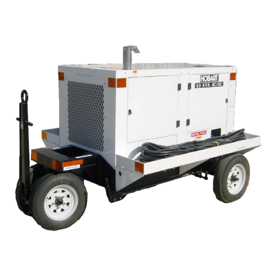
OM-2098C / Operation and Maintenance Manual 60CU24 / Series 500060C / 400 Hz. Generator Set Physical Basic Unit (Fixed Mount) Trailer Mounted Unit Length 68 in. (172.7 mm) 94.5 in. (240 mm) Width 37 in. (94 mm) 67 in. (170.1 mm) Height 46 in. -
Page 18: Engine And Generator
OM-2098C / Operation and Maintenance Manual 60CU24 / Series 500060C / 400 Hz. Generator Set GENERATOR PROTECTIVE SYSTEM Over voltage Trips at 126 volts after a 1 second time delay. Trips at 140 volts in 160 milliseconds. Trips at 180 volts in 50 milliseconds. - Page 19 Hobart Installed Equipment This generator set is modified at Hobart Brothers by the addition of the following equipment: (1) Shut Down/Reset device In addition to the other devices provided by the engine manufacturer, the factory also added an engine shutdown/reset feature.
- Page 20 OM-2098C / Operation and Maintenance Manual 60CU24 / Series 500060C / 400 Hz. Generator Set To operate the EMERGENCY SHUTDOWN/RESET SWITCH: • Push button in until engine stops or until button travel stops • Pull the button back out to reset Coolant high temperature shutdown system The coolant temperature shutdown system consists of a factory supplied temperature switch.
- Page 21 OM-2098C / Operation and Maintenance Manual 60CU24 / Series 500060C / 400 Hz. Generator Set ENGINE FAULTS Engine Fault Condition What Occurs How To Reset Over temperature or low oil Shuts down the engine, and will be a) Press the engine stop button to...
-
Page 22: General 3
OM-2098C / Operation and Maintenance Manual 60CU24 / Series 500060C / 400 Hz. Generator Set 1. Control Panel 6. Emergency Stop Switch (S28) 2. Operator’s Push-Button Panel 7. Exhaust Outlet 3. Output Cable Location 8. Canopy 4. Front Axle Assembly 9. -
Page 23: Revision 8
OM-2098C / Operation and Maintenance Manual 60CU24 / Series 500060C / 400 Hz. Generator Set 1. Radiator 4. Control Box 2. Cummins QSB Engine Fuel Tank 3. Air Cleaner Generator Main Components of Generator Set Figure 5 November 16, 2007... -
Page 24: Control Box Assembly
OM-2098C / Operation and Maintenance Manual 60CU24 / Series 500060C / 400 Hz. Generator Set Air Cleaner Service Indicator Air Cleaner and Service Indicator Figure 6 7) Control Box Assembly The control box is a sheet metal enclosure that houses and provides mounting facilities for engine and generator controls and monitoring equipment. - Page 25 OM-2098C / Operation and Maintenance Manual 60CU24 / Series 500060C / 400 Hz. Generator Set 7,10 10,12 10,11 10,15 10,16 1. Fuel Gage (M13) 10. Strip Lights (DS60-DS62) (3) [Not Shown] 2. Front Panel 11. AC Generator Ammeter (M1) 3. Engine Coolant Temperature Gauge (M24) 12.
- Page 26 OM-2098C / Operation and Maintenance Manual 60CU24 / Series 500060C / 400 Hz. Generator Set 1. Meter Selector Switch (S3) 6. AC Output No. 2 (S275) [if applicable] 2. Test/Reset Switch (S77) 7. AC Output No. 1 (S75) 3. Engine Stop Switch (S76) 8.
- Page 27 OM-2098C / Operation and Maintenance Manual 60CU24 / Series 500060C / 400 Hz. Generator Set 1. Engine Specific PC Board [ESB] (A1) 6. +5, -12 VDC Power Supply (PS1) 2. Engine Interface PC Board [EIB] (A2) 7. Circuit Breaker Support Bracket 3.
- Page 28 OM-2098C / Operation and Maintenance Manual 60CU24 / Series 500060C / 400 Hz. Generator Set (5) Engine coolant temperature gage The temperature gage is an electrical type that is connected by a wire to a water temperature sensor installed in the engine cooling system. The gage indicates engine coolant temperature in the range of 100-280 º...
- Page 29 OM-2098C / Operation and Maintenance Manual 60CU24 / Series 500060C / 400 Hz. Generator Set (11) Fault Code meter and “TEST/RESET” push-button switch (M6, S77) The function of the fault code meter is to indicate to the operator, that an abnormal condition of over voltage, under frequency, etc.
- Page 30 OM-2098C / Operation and Maintenance Manual 60CU24 / Series 500060C / 400 Hz. Generator Set (18) “DC OUTPUT” Contactor Switch (S430) [Optional with TR, Reference Appendix A] Each time the “DC OUTPUT” push-button switch is pressed, the BLUE indicator will glow when the circuit is energized, indicating that power is available at the plug.
- Page 31 OM-2098C / Operation and Maintenance Manual 60CU24 / Series 500060C / 400 Hz. Generator Set J54 Connector PC Board Software EF1 Bypass EF2 Bypass (if applicable) Service Tool Connector Digital Control PC Board Figure 10 (6) Engine Specific PC Board [ESB] (A1) The ESB (see figure 12) is unique only to the engine model used in the GPU purchased.
- Page 32 OM-2098C / Operation and Maintenance Manual 60CU24 / Series 500060C / 400 Hz. Generator Set Starter Disable/Enable J51 Connector PC Board Software Engine Interface PC Board Figure 11 Engine Status Switch Frequency Adjustment & Enable/Disable Switch J52 Connector Engine Status Lights...
- Page 33 OM-2098C / Operation and Maintenance Manual 60CU24 / Series 500060C / 400 Hz. Generator Set Regulated/Diagnostic J53 Connector PC Board Software Voltage Adjustment, Coarse Voltage Adjustment, Fine LDC Control Voltage Regulator PC Board Figure 13 (7) Voltage regulator PC board [REG] (A4) This voltage regulator PC board (see Figure 13) is designed to provide voltage regulation for a three-phase, four-wire, 115/200-volt, 400-Hz brushless alternator.
- Page 34 OM-2098C / Operation and Maintenance Manual 60CU24 / Series 500060C / 400 Hz. Generator Set When the alternator is loaded, its terminal voltage decreases, lowering the rectified three- phase voltage of the voltage sensing circuit. The sensing voltage is low in respect to its reference voltage, causing the voltage regulator PC circuitry to increase the power to the field of the rotary exciter.
-
Page 35: Power Module Panel Assembly
OM-2098C / Operation and Maintenance Manual 60CU24 / Series 500060C / 400 Hz. Generator Set J401 Connector PC Board Software Transformer-Rectifier PC Board Figure 15 8) Power Module Panel Assembly (Figure 16) The power module panel assembly sometimes referred to as the contactor panel, is located at the left front of the machine under the control box. -
Page 36: Cold Weather Starting System
OM-2098C / Operation and Maintenance Manual 60CU24 / Series 500060C / 400 Hz. Generator Set (1) Line-Drop Compensation The current transformers detects the magnitude and power factor of current flowing from generator to load. They feed a signal to the voltage regulator that interprets the signal and alters the exciter field current as required to maintain a constant predetermined voltage at the load. - Page 37 OM-2098C / Operation and Maintenance Manual 60CU24 / Series 500060C / 400 Hz. Generator Set 1. Output #1 Contactor (S75) 2. Wire Harness 3. Output #2 Contactor (S275) (If Applicable) Output Power Module Components Figure 16 November 16, 2007 Chapter 1-1...
- Page 38 OM-2098C / Operation and Maintenance Manual 60CU24 / Series 500060C / 400 Hz. Generator Set This page intentionally left blank. November 16, 2007 Chapter 1-1 Revision 8 Page 24...
-
Page 39: Preparation For Use, Storage Or Shipping
OM-2098C / Operation and Maintenance Manual 60CU24 / Series 500060C / 400 Hz. Generator Set Section 2 Preparation for Use, Storage, or Shipping 1) Preparation for Use a) Inspection/Check Inspect the unit thoroughly prior to operation. (1) Remove blocking, banding, ties, and other securing material. - Page 40 OM-2098C / Operation and Maintenance Manual 60CU24 / Series 500060C / 400 Hz. Generator Set Engine lubricating oil level The oil gage rod has “H” high mark and “L” low level marks to indicate the operating lubrication oil supply. Oil level should be kept as near the high mark as possible, without going over it.
-
Page 41: Tips On Cold Weather Starting
OM-2098C / Operation and Maintenance Manual 60CU24 / Series 500060C / 400 Hz. Generator Set To install AC output cables proceed as follows: (1) Open control box door of the generator set and remove the lower panel. (2) Remove Plexiglas cover in front of the power module assembly. - Page 42 OM-2098C / Operation and Maintenance Manual 60CU24 / Series 500060C / 400 Hz. Generator Set a) General Pull all circuit breakers and/or disconnect battery negative terminal. (1) The unit should be prepared for storage as soon as possible after being removed from service.
-
Page 43: Preparation For Shipment
OM-2098C / Operation and Maintenance Manual 60CU24 / Series 500060C / 400 Hz. Generator Set (3) While the engine is running, ensure that normal operating controls are in good working condition before shutdown and storage. If weekly operation is not possible, contact the nearest engine manufacturer distributor for instructions. - Page 44 OM-2098C / Operation and Maintenance Manual 60CU24 / Series 500060C / 400 Hz. Generator Set This page intentionally left blank. April 01, 2005 Chapter 1-2 Page 6...
-
Page 45: Operation
OM-2098C / Operation and Maintenance Manual 60CU24 / Series 500060C / 400 Hz. Generator Set Section 3 Operation 1) General This section contains information and instructions for the safe and efficient operation of the equipment. Operating instructions are presented in step-by-step sequence of procedures to be followed in supplying 400-Hz power or 28.5V DC power. - Page 46 OM-2098C / Operation and Maintenance Manual 60CU24 / Series 500060C / 400 Hz. Generator Set 7,10 10,12 10,11 10,15 10,16 1. Fuel Gage (M13) 10. Strip Lights (DS60-DS62) [Not Shown] 2. Front Panel 11. AC Generator Ammeter (M1) 3. Engine Coolant Temperature Gauge (M24) 12.
- Page 47 OM-2098C / Operation and Maintenance Manual 60CU24 / Series 500060C / 400 Hz. Generator Set 1. Meter Selector Switch (S3) 6. AC Output No. 2 (S275) [if applicable] 2. Test/Reset Switch (S77) 7. AC Output No. 1 (S75) 3. Engine Stop Switch (S76) 8.
- Page 48 OM-2098C / Operation and Maintenance Manual 60CU24 / Series 500060C / 400 Hz. Generator Set CAUTION Never use an ether start system in conjunction with the air intake heater. (3) Press the green “ENGINE START” push-button switch and hold until engine starts. The engine will start at idle speed, and the green light in the “ENGINE START”...
- Page 49 OM-2098C / Operation and Maintenance Manual 60CU24 / Series 500060C / 400 Hz. Generator Set (2) Observe generator instruments. The frequency meter should indicate exactly 400 Hz. With the “METER SELECT” push button switch set to read any line-to-neutral position, (A-N, B-N, or C- N), the voltmeter should read 115 volts.
- Page 50 OM-2098C / Operation and Maintenance Manual 60CU24 / Series 500060C / 400 Hz. Generator Set Discontinue Power Delivery with Unit Shutdown (1) Normal conditions Push the load contactor(s) (“OUTPUT NO. 1” or “OUTPUT NO. 2”, if applicable) push button switch to open the contactor. The indicating light (yellow or orange depending on the contactor used) on that switch will go OFF immediately to indicate that the load contactor has opened and power is no longer being delivered to the aircraft.
-
Page 51: Maintenance Inspection/Check
OM-2098C / Operation and Maintenance Manual 60CU24 / Series 500060C / 400 Hz. Generator Set Chapter 2 Service and Troubleshooting Section 1 Maintenance Inspection/Check 1) General To make certain the generator set is always ready for operation, it must be inspected and maintained regularly and systematically so that defects may be discovered and corrected before they result in serious damage to components, or failure of the equipment. - Page 52 OM-2098C / Operation and Maintenance Manual 60CU24 / Series 500060C / 400 Hz. Generator Set Hourly Interval 50-150 1000 1500 2000 Calendar Interval Once Daily 3 Mo. 6 Mo. 1 Yr. 1.5 Yr. 2 Yr. Symbol Engine Change Air Cleaner Cartridge...
-
Page 53: Inspection/Check
OM-2098C / Operation and Maintenance Manual 60CU24 / Series 500060C / 400 Hz. Generator Set Hourly Interval 50-150 1000 1500 2000 Calendar Interval Once Daily 3 Mo. 6 Mo. 1 Yr. 1.5 Yr. 2 Yr. Symbol Engine (continued) Flush and Change Coolant Check Fan Mounting Spring &... - Page 54 OM-2098C / Operation and Maintenance Manual 60CU24 / Series 500060C / 400 Hz. Generator Set b) “AR” Checks and Operations (As Required) (1) Engine Change Air Cleaner A definite time schedule for changing the air cleaner cannot be established. This filter should not be washed more then six times or retained for more than one year of service, which ever comes first.
- Page 55 OM-2098C / Operation and Maintenance Manual 60CU24 / Series 500060C / 400 Hz. Generator Set Steam clean the engine to free it of oil and dirt to prevent uneven engine cooling “hot spots”. The oil and dirt can also fall into the engine and fuel system when covers are removed during repair work.
- Page 56 OM-2098C / Operation and Maintenance Manual 60CU24 / Series 500060C / 400 Hz. Generator Set Check for Leaks and Correct At each daily start-up, check for coolant, fuel, and oil leaks. Coolant leaks may be more noticeable when components are cold. Observe pumps, hoses, fittings, gasket connections, etc., for signs of leakage.
- Page 57 OM-2098C / Operation and Maintenance Manual 60CU24 / Series 500060C / 400 Hz. Generator Set Check Alternator Charging Rate Observe the 12 VDC ammeter each time the engine is started. A zero amperage reading or extremely high reading for any length of time indicates trouble in the alternator, regulator, battery, or interconnecting wiring.
- Page 58 OM-2098C / Operation and Maintenance Manual 60CU24 / Series 500060C / 400 Hz. Generator Set (2) Electrical (12 VDC system) NOTE: The battery furnished with this generator set is MAINTENANCE FREE. Battery Electrolyte Level (if applicable) Battery electrolyte level must be maintained above top of plates. Add distilled water as required.
- Page 59 OM-2098C / Operation and Maintenance Manual 60CU24 / Series 500060C / 400 Hz. Generator Set Connections Inspect connectors for damaged or corroded condition. (3) Electrical (400 Hz System) Protective Monitoring Circuits Check operation of all protective monitoring circuits to make certain they will function if a fault should occurs in the output circuit.
- Page 60 OM-2098C / Operation and Maintenance Manual 60CU24 / Series 500060C / 400 Hz. Generator Set h) “E” Checks and Operations (1500 Hours or 1.5 Year) (1) Engine Steam Clean Engine There are several reasons why the engine exterior should be kept clean. Dirt on the outside will enter fuel and oil filter cases and rocker housings when covers are removed, unless dirt is removed first.
- Page 61 OM-2098C / Operation and Maintenance Manual 60CU24 / Series 500060C / 400 Hz. Generator Set Flush cooling system and change coolant. Seasonal Maintenance Checks Spring/Fall (Engine) (1) Check Fan Mounting Check fan to be sure it is securely mounted. Check for fan wobble and/or broken/cracked blades.
- Page 62 OM-2098C / Operation and Maintenance Manual 60CU24 / Series 500060C / 400 Hz. Generator Set In addition to daily checks of hoses for leaks, inspect hoses thoroughly each time the cooling system is cleaned and serviced. Inspect for signs of deterioration and collapse. Inspect for cracks and cuts. Inspect for cutting and deformation caused by hose clamps.
- Page 63 OM-2098C / Operation and Maintenance Manual 60CU24 / Series 500060C / 400 Hz. Generator Set Lamp (Bulb) as per Lamp Light Identification Location Industry Trade Number or Description Instrument Panel Lights Switch Panel Engine Start Indicator Switch Panel 1815 Engine Stop Indicator...
- Page 64 OM-2098C / Operation and Maintenance Manual 60CU24 / Series 500060C / 400 Hz. Generator Set This page intentionally left blank. April 01, 2005 Chapter 2-1 Page 14...
-
Page 65: Maintenance Procedures
OM-2098C / Operation and Maintenance Manual 60CU24 / Series 500060C / 400 Hz. Generator Set Section 2 Maintenance Procedures 1) General A suggested maintenance schedule was provided in Section 1 of this Servicing Chapter. Each step of the schedule was also covered in general in Section 1. This Section covers maintenance in more detail, where necessary. - Page 66 OM-2098C / Operation and Maintenance Manual 60CU24 / Series 500060C / 400 Hz. Generator Set Oil recommended for the diesel engines in this application is API Class CCMC. Lubricating oil is discussed in detail in the engine manufacturer’s operation manual.
- Page 67 OM-2098C / Operation and Maintenance Manual 60CU24 / Series 500060C / 400 Hz. Generator Set Item Maintenance Required Check oil level daily or after every 10 hours of use. Change oil and the oil filter Lube Oil after the first 50 to 150 hours of use, then at 250 hour or 3 month intervals thereafter.
- Page 68 OM-2098C / Operation and Maintenance Manual 60CU24 / Series 500060C / 400 Hz. Generator Set Symbol Name Specification Notes Grease, General Purpose MIL-G-3545 Excludes those of sodium or soda soap thickness. Oil, Engine, Heavy Duty API Class CC Must contain as but not more than 1.85%...
-
Page 69: Servicing The Air Cleaner
OM-2098C / Operation and Maintenance Manual 60CU24 / Series 500060C / 400 Hz. Generator Set Use the oil refill tube to refill the crankcase with new, clean oil that meets engine manufacturer’s recommendations. NOTE: Using a funnel to fill the oil crankcase will help prevent spills. -
Page 70: Engine Fuel
OM-2098C / Operation and Maintenance Manual 60CU24 / Series 500060C / 400 Hz. Generator Set Air Cleaner Assembly Figure 3 Service Indicator Air Cleaner a) Inspecting the Air Cleaner (1) Make periodic checks of air cleaner inlet screen for obstructions. If any obstructions are present, remove them. -
Page 71: Engine Fuel System
OM-2098C / Operation and Maintenance Manual 60CU24 / Series 500060C / 400 Hz. Generator Set CAUTION Due to the precise tolerances of diesel injection systems, it is extremely important that the fuel be kept clean and free of dirt or water. Dirt or water in the system can cause severe damage to both the injection pump and the injection nozzles. - Page 72 OM-2098C / Operation and Maintenance Manual 60CU24 / Series 500060C / 400 Hz. Generator Set (1) Draining the fuel water separator bowl. Open drain valve Drain accumulated water and contaminants. Close drain valve. (2) Priming fuel water separator (when applicable).
- Page 73 OM-2098C / Operation and Maintenance Manual 60CU24 / Series 500060C / 400 Hz. Generator Set Fuel/Water Separator Filter Drain Fuel/Water Separator and Lubricity Fuel Filter Figure 4 (1) Changing the lubricity fuel filter Replacement fuel filter part number: • Equipment Manufacturer Part No. 286897-026 •...
-
Page 74: Engine Cooling System
OM-2098C / Operation and Maintenance Manual 60CU24 / Series 500060C / 400 Hz. Generator Set Fill new filter with diesel fuel Screw in the new fuel filter “snug”. Check that the cartridge is seated correctly against the gasket and tighten with a final half turn. - Page 75 OM-2098C / Operation and Maintenance Manual 60CU24 / Series 500060C / 400 Hz. Generator Set (2) Removal To remove, turn the cap to the left (counterclockwise) to the safety stop. When all pressure is released, press down on the cap and continue to turn until the cap is free to be removed.
- Page 76 OM-2098C / Operation and Maintenance Manual 60CU24 / Series 500060C / 400 Hz. Generator Set d) Draining the Cooling System To completely empty the cooling system requires draining the engine block (if furnished) and the radiator assembly. Both of the drain valves (radiator and block drain), can be opened/closed at the same time but they do not need to be.
-
Page 77: Generator Maintenance
OM-2098C / Operation and Maintenance Manual 60CU24 / Series 500060C / 400 Hz. Generator Set Continue to check coolant level until all trapped air escapes. Add coolant if needed to fill to the bottom of fill neck. Install radiator cap. - Page 78 OM-2098C / Operation and Maintenance Manual 60CU24 / Series 500060C / 400 Hz. Generator Set c) Checking Belt Tension CAUTION Checking the tension and changing the serpentine belt should only be performed with the engine off. Check belt tension every 1000 hours, or once year, whichever comes first. A belt that is too tight is destructive to bearings of the driven part.
-
Page 79: Adjustments / Tests
OM-2098C / Operation and Maintenance Manual 60CU24 / Series 500060C / 400 Hz. Generator Set Section 3 Adjustment/Test 1) General These adjustments and test procedures are applicable to testing and adjusting the generator set after major repair, major parts replacements, or overhaul. - Page 80 OM-2098C / Operation and Maintenance Manual 60CU24 / Series 500060C / 400 Hz. Generator Set 7,10 10,12 10,11 10,15 10,16 1. Fuel Gage (M13) 10. Strip Lights (DS60-DS62) [Not Shown] 2. Front Panel 11. AC Generator Ammeter (M1) 3. Engine Coolant Temperature Gauge (M24) 12.
- Page 81 OM-2098C / Operation and Maintenance Manual 60CU24 / Series 500060C / 400 Hz. Generator Set 1. Meter Selector Switch (S3) 6. AC Output No. 2 (S275) [if applicable] 2. Test/Reset Switch (S77) 7. AC Output No. 1 (S75) 3. Engine Stop Switch (S76) 8.
- Page 82 OM-2098C / Operation and Maintenance Manual 60CU24 / Series 500060C / 400 Hz. Generator Set 1. Engine Specific PC Board [ESB] (A1) 6. +5, -12 VDC Power Supply (PS1) 2. Engine Interface PC Board [EIB] (A2) 7. Circuit Breaker Support Bracket 3.
- Page 83 OM-2098C / Operation and Maintenance Manual 60CU24 / Series 500060C / 400 Hz. Generator Set (5) Position switches and controls for automatic voltage regulation and power delivery as follows: Place regulated-diagnostic switch (Figure 8) in “REGULATED” position. Place EF Bypass switches (Figure 4) in “BYPASS / OFF” position.
- Page 84 OM-2098C / Operation and Maintenance Manual 60CU24 / Series 500060C / 400 Hz. Generator Set PC Board Software EF1 Bypass EF2 Bypass, if applicable Service Tool Connector Digital Control PC Board Figure 4 (3) Verify that when the EF Bypass switch (Figure 4) is in the “BYPASS / ON” position or the “BYPASS / OFF”...
- Page 85 OM-2098C / Operation and Maintenance Manual 60CU24 / Series 500060C / 400 Hz. Generator Set (Steps 7 - 11 are only required if EF interlock system is not available on a load bank.) (7) Connect a source of 24 V-DC power (two twelve-volt batteries connected in series) to terminals N, F (or E) at the output terminal panel.
- Page 86 OM-2098C / Operation and Maintenance Manual 60CU24 / Series 500060C / 400 Hz. Generator Set (15) Check voltage regulator, at intervals, from no load to full load. Observe and note voltage at various loads. Steady-state voltages should vary no more than +/- 1% from normal output voltage.
- Page 87 OM-2098C / Operation and Maintenance Manual 60CU24 / Series 500060C / 400 Hz. Generator Set NOTE: Make all protective system tests with the unit operating under a load for the following steps. Reference Chapter 2, Section 4, for all fault codes.
- Page 88 OM-2098C / Operation and Maintenance Manual 60CU24 / Series 500060C / 400 Hz. Generator Set While the unit is operating normally under load, set the frequency adjust switch (Figure 6) to “TEST”. Use the frequency adjust potentiometer (Figure 6) to adjust frequency to 400 HZ.
- Page 89 OM-2098C / Operation and Maintenance Manual 60CU24 / Series 500060C / 400 Hz. Generator Set If the protective circuit opens the load contactor and displays fault “70.22” on the fault code after 5 seconds at 426 Hz, all components of the system are functioning properly.
-
Page 90: Generator Set Adjustments
OM-2098C / Operation and Maintenance Manual 60CU24 / Series 500060C / 400 Hz. Generator Set (3) If no active codes are recorded, both the “Engine Stop” (Figure 6) and “Check Engine” (Figure 6) lamps will come on and stay on. - Page 91 OM-2098C / Operation and Maintenance Manual 60CU24 / Series 500060C / 400 Hz. Generator Set b) Adjust 400 Hz voltage regulator. When a voltage regulator is first put into service, or when output (generator-to-aircraft) cables are changed, the regulator may require adjustments of output voltage value and line-drop compensation.
- Page 92 OM-2098C / Operation and Maintenance Manual 60CU24 / Series 500060C / 400 Hz. Generator Set (1) Output Voltage Adjustment Adjust Voltage Control The output voltage, at which the generator is regulated, is adjustable by the fine voltage adjustment potentiometer (Figure 8). Turn the potentiometer adjustment clockwise to increase generator output voltage, and counterclockwise to decrease voltage.
-
Page 93: Generator And Exciter Test
OM-2098C / Operation and Maintenance Manual 60CU24 / Series 500060C / 400 Hz. Generator Set Engine idle speed is programmed at the factory. If adjustment is required, contact the local engine distributor. The recommended idle speed is 1000 RPM, +/- 25 RPM. -
Page 94: Diode Test
OM-2098C / Operation and Maintenance Manual 60CU24 / Series 500060C / 400 Hz. Generator Set Test Connection Resistance (Ohms) Generator Stator Phase A to N (G1)* 0.00235 Generator Stator Phase B to N (G1)* 0.00235 Generator Stator Phase C to N (G1)* 0.00235... -
Page 95: Troubleshooting Procedures
OM-2098C / Operation and Maintenance Manual 60CU24 / Series 500060C / 400 Hz. Generator Set Section 4 Troubleshooting Procedures 1) General The Troubleshooting Chart (See Appendix A for the 28.5 VDC Transformer-Rectifier troubleshooting information.) and Fault Code Chart, located in this section, covers the common faults and malfunctions that you may find during operation or maintenance of this equipment. -
Page 96: 400 Hz. Test Values
OM-2098C / Operation and Maintenance Manual 60CU24 / Series 500060C / 400 Hz. Generator Set 4) 400 Hz. Test Values Although test values are provided throughout the troubleshooting chart, additional information and values are given here. Generator output voltage at maximum voltage regulator potentiometer setting: 134 volts or higher. -
Page 97: Gpu Control Monitoring
OM-2098C / Operation and Maintenance Manual 60CU24 / Series 500060C / 400 Hz. Generator Set 9) GPU Control Monitoring The GPU control system performs complete diagnostic testing and continuous monitoring of all critical circuits and operating electrical values. If the control system senses a problem with one of the circuits or if any of the electrical values exceeds its safe operating limit, the control system will shut the GPU down, or may allow the GPU to continue operation depending on the severity of the condition. - Page 98 OM-2098C / Operation and Maintenance Manual 60CU24 / Series 500060C / 400 Hz. Generator Set (3) Engine Idle Mode When the engine has been started, the engine will begin in the idle mode. The “ENGINE START” push-button will flash indicating the engine is in the idle mode.
- Page 99 OM-2098C / Operation and Maintenance Manual 60CU24 / Series 500060C / 400 Hz. Generator Set (1) Warning Warning faults are faults that occur and have no effect on the operation of the GPU. An example would be an intake air restriction fault due to a dirty filter. Although the GPU will continue to operate, the fault will appear on the fault code display.
- Page 100 OM-2098C / Operation and Maintenance Manual 60CU24 / Series 500060C / 400 Hz. Generator Set Command Fault 70.67 Fault Codes Fault Meter Display Figure 1 d) Operation Monitoring While applying power to an aircraft, the GPU continually monitors all critical circuits and operating electrical values.
- Page 101 OM-2098C / Operation and Maintenance Manual 60CU24 / Series 500060C / 400 Hz. Generator Set Record Designator Record Number - 1 21 Fault Record Number “121” Fault Meter Display (Fault Record Number) Figure 1A (4) Release the “TEST/RESET” push button and the display will alternate between the fault record number (See Figure 1A) and the fault code (See Figure 1).
- Page 102 OM-2098C / Operation and Maintenance Manual 60CU24 / Series 500060C / 400 Hz. Generator Set 7,10 10,12 10,11 10,15 10,16 1. Fuel Gage (M13) 10. Strip Lights (DS60-DS62) [Not Shown] 2. Front Panel 11. AC Generator Ammeter (M1) 3. Engine Coolant Temperature Gauge (M24) 12.
- Page 103 OM-2098C / Operation and Maintenance Manual 60CU24 / Series 500060C / 400 Hz. Generator Set 1. Meter Selector Switch (S3) 6. AC Output No. 2 (S275) [if applicable] 2. Test/Reset Switch (S77) 7. AC Output No. 1 (S75) 3. Engine Stop Switch (S76) 8.
- Page 104 OM-2098C / Operation and Maintenance Manual 60CU24 / Series 500060C / 400 Hz. Generator Set 1. Engine Specific PC Board [ESB] (A1) 6. +5, -12 VDC Power Supply (PS1) 2. Engine Interface PC Board [EIB] (A2) 7. Circuit Breaker Support Bracket 3.
-
Page 105: Engine Controls
OM-2098C / Operation and Maintenance Manual 60CU24 / Series 500060C / 400 Hz. Generator Set Trouble, Symptom, Condition Probable Cause Test, Check, and/or Remedy Engine Controls 1. Engine will not start. Starter a. Battery discharged, or loose Check voltage across batteries. - Page 106 OM-2098C / Operation and Maintenance Manual 60CU24 / Series 500060C / 400 Hz. Generator Set Trouble, Symptom, Condition Probable Cause Test, Check, and/or Remedy Engine Controls (continued) 1. Engine will not start. Starter g. Defective EIB Board. Replace EIB board.
- Page 107 OM-2098C / Operation and Maintenance Manual 60CU24 / Series 500060C / 400 Hz. Generator Set Trouble, Symptom, Condition Probable Cause Test, Check, and/or Remedy Engine Controls (continued) 5. Engine is hard to start. a. Low compression, which may Check compression in accordance...
-
Page 108: Generator Excitation Circuits
OM-2098C / Operation and Maintenance Manual 60CU24 / Series 500060C / 400 Hz. Generator Set Trouble, Symptom, Condition Probable Cause Test, Check, and/or Remedy Engine Controls (continued) 11. Engine lacks power a. Improper engine adjustments “Tune-up” engine in accordance and gear train timing with engine manufacturer’s... -
Page 109: No. 1 Load Contactor Operating Circuit
OM-2098C / Operation and Maintenance Manual 60CU24 / Series 500060C / 400 Hz. Generator Set Trouble, Symptom, Condition Probable Cause Test, Check, and/or Remedy Generator Excitation Circuits (continued) 1. No (or low) generator output e. Defective connector at voltage Disconnect exciter wires at voltage in all phases. - Page 110 OM-2098C / Operation and Maintenance Manual 60CU24 / Series 500060C / 400 Hz. Generator Set Trouble, Symptom, Condition Probable Cause Test, Check, and/or Remedy No. 1 Load Contactor Operating Circuit (Continued) 1. Load contactor (K1) will not f. Defective coil in load contactor Disconnect leads at load contactor close when output No.
-
Page 111: No. 2 Load Contactor Operating Circuit
OM-2098C / Operation and Maintenance Manual 60CU24 / Series 500060C / 400 Hz. Generator Set Trouble, Symptom, Condition Probable Cause Test, Check, and/or Remedy No. 2 Load Contactor Operating Circuit (if applicable) 1. Load contactor (K1) will not a. Defective circuit breaker (CB2). - Page 112 OM-2098C / Operation and Maintenance Manual 60CU24 / Series 500060C / 400 Hz. Generator Set Trouble, Symptom, Condition Probable Cause Test, Check, and/or Remedy No. 2 Load Contactor Operating Circuit (if applicable) [continued] 1. Load contactor (K201) will not f. Defective coil in load contactor Disconnect leads at load contactor close when output No.
-
Page 113: Protective Circuit
OM-2098C / Operation and Maintenance Manual 60CU24 / Series 500060C / 400 Hz. Generator Set Trouble, Symptom, Condition Probable Cause Test, Check, and/or Remedy Protective Circuit NOTE: Protective monitoring is not completely functional until load contactor is CLOSED. Since it is not advisable to vary voltages for test purposes while delivering power to an aircraft, the GPU should be connected to a load bank for trouble shooting protective circuits. -
Page 114: Generator
OM-2098C / Operation and Maintenance Manual 60CU24 / Series 500060C / 400 Hz. Generator Set Trouble, Symptom, Condition Probable Cause Test, Check, and/or Remedy Protective Circuit (continued) NOTE: Protective monitoring is not completely functional until load contactor is CLOSED. Since it is not advisable to vary voltages for test purposes while delivering power to an aircraft, the GPU should be connected to a load bank for trouble shooting protective circuits. - Page 115 OM-2098C / Operation and Maintenance Manual 60CU24 / Series 500060C / 400 Hz. Generator Set Trouble, Symptom, Condition Probable Cause Test, Check, and/or Remedy Generator (continued) 3. Generator overheats b. Improper or blocked ventilation. Check for foreign material (rags, (continued) etc.) blocking air-flow.
- Page 116 OM-2098C / Operation and Maintenance Manual 60CU24 / Series 500060C / 400 Hz. Generator Set Troubleshooting Table GPU Commands Name Description code 00. _ _ Invalid Command 01. _ _ ENGINE SELF TEST CMD All boards test the communication between each other.
- Page 117 OM-2098C / Operation and Maintenance Manual 60CU24 / Series 500060C / 400 Hz. Generator Set Troubleshooting Table GPU Commands Name Description code 31. _ _ 32. _ _ 33. _ _ 34. _ _ 35. _ _ 36. _ _ 37.
- Page 118 OM-2098C / Operation and Maintenance Manual 60CU24 / Series 500060C / 400 Hz. Generator Set Troubleshooting Table GPU Commands Name Description code 62. _ _ 63. _ _ REG TEST OUTPUT FREQUENCY Check for 400 Hz. output frequency. 64. _ _ 65.
- Page 119 OM-2098C / Operation and Maintenance Manual 60CU24 / Series 500060C / 400 Hz. Generator Set Troubleshooting Table GPU Commands Name Description code 93. _ _ 94. _ _ 95. _ _ 96. _ _ 97. _ _ 98. _ _ 99.
- Page 120 OM-2098C / Operation and Maintenance Manual 60CU24 / Series 500060C / 400 Hz. Generator Set Troubleshooting Table Faults Fault Name Possible Cause(s) Corrective Action code _ _.00 Invalid Fault _ _.01 _ _.02 _ _.03 CTL MEMORY FAULT CTL board defective Replace the CTL board.
- Page 121 OM-2098C / Operation and Maintenance Manual 60CU24 / Series 500060C / 400 Hz. Generator Set Troubleshooting Table Faults Fault Name Possible Cause(s) Corrective Action code REG OUTPUT UNDER FREQ Defective engine ECM. Replace engine ECM. _ _.23 FAULT Defective REG board.
- Page 122 OM-2098C / Operation and Maintenance Manual 60CU24 / Series 500060C / 400 Hz. Generator Set Troubleshooting Table Faults Fault Name Possible Cause(s) Corrective Action code TRB INPUT CONTACTOR Defective input contactor. Replace input contactor. _ _.46 FAULT Defective TRB board.
- Page 123 OM-2098C / Operation and Maintenance Manual 60CU24 / Series 500060C / 400 Hz. Generator Set Troubleshooting Table Faults Fault Name Possible Cause(s) Corrective Action code _ _.69 _ _.70 _ _.71 _ _.72 _ _.73 _ _.74 _ _.75 _ _.76 _ _.77...
- Page 124 OM-2098C / Operation and Maintenance Manual 60CU24 / Series 500060C / 400 Hz. Generator Set This page intentionally left blank. April 01, 2005 Chapter 2-4 Page 30...
-
Page 125: Overhaul / Major Repair
OM-2098C / Operation and Maintenance Manual 60CU24 / Series 500060C / 400 Hz. Generator Set Chapter 3 Overhaul/Major Repair Section 1 Exciter Armature 1) General This section provides information and instructions for removal and installation of the exciter armature used on this generator set. Through design improvements, the exciter and rear main bearing can be removed without removing the generator from the generator set. -
Page 126: Exciter Armature
OM-2098C / Operation and Maintenance Manual 60CU24 / Series 500060C / 400 Hz. Generator Set 1. Exciter Core Flange 4. Diode Mounting Plate 2. Exciter Core Lamination 5. Silicon Diode 3. Banding Glass Tape Exciter Armature Figure 2 The exciter armature covered by the manual is mounted on the rear portion of the main generator armature shaft which extends rearward, beyond the rear generator bearing, into the exciter housing (See Figure 1). -
Page 127: General
OM-2098C / Operation and Maintenance Manual 60CU24 / Series 500060C / 400 Hz. Generator Set The exciter armature is mounted on the main generator armature shaft with a 3/8-inch square machine key and is held in place by a ½ - 13 hex head cap screw in the center of the diode mounting plate. - Page 128 OM-2098C / Operation and Maintenance Manual 60CU24 / Series 500060C / 400 Hz. Generator Set Sling Hammer Assembly .421 Drill 1.25 in. Deep; Tap ½-13 UNC-2B, 1 in. Deep .578 in. Diameter Sling Hammer Components 1. Stud, ¼ - 28 UNF 2A, Grade 5 or 8 ONLY 4.
- Page 129 OM-2098C / Operation and Maintenance Manual 60CU24 / Series 500060C / 400 Hz. Generator Set (3) Remove exciter housing cover as required. Remove the ½ - 13 cap screw, which holds the exciter armature and key retainer on the generator shaft.
-
Page 130: Installation Exciter Armature
OM-2098C / Operation and Maintenance Manual 60CU24 / Series 500060C / 400 Hz. Generator Set CAUTION Leads may be damaged if armature is turned too far in either direction. Place a block bar (pry bar) into the generator fan assembly to keep the generator armature from rotating. - Page 131 OM-2098C / Operation and Maintenance Manual 60CU24 / Series 500060C / 400 Hz. Generator Set contacts the end of the generator shaft, just as is shown in the lower portion of Figure 5. After installation, remove the bolt and nut.
- Page 132 OM-2098C / Operation and Maintenance Manual 60CU24 / Series 500060C / 400 Hz. Generator Set NOTE: Application of “Loctite” is to compensate for any looseness in machine key and keyway (up to 0.005 inch). Manufacturers of LOCTITE and other recommended products are listed below.
- Page 133 OM-2098C / Operation and Maintenance Manual 60CU24 / Series 500060C / 400 Hz. Generator Set Exciter Armature Diode Mounting Plate Generator Armature Shaft ½ -13 Nut ½ - 13 x 5-Inch Bolt ½ - 13 Threaded Hole In Armature Shaft Exciter Armature After Installation On Armature Shaft (Remove the ½...
- Page 134 OM-2098C / Operation and Maintenance Manual 60CU24 / Series 500060C / 400 Hz. Generator Set This page intentionally left blank. April 01, 2005 Chapter 3-1 Page 10...
-
Page 135: Dual Bearing Flexible Coupling
Hobart Ground Power as Part Number 281701. This assembly is illustrated in Figure 1. The primary function of this assembly is to couple a Hobart 2400 RPM Generator to a Diesel engine. The flexible coupling assembly compensates for slight misalignment between the engine and the generator, due to manufacturing tolerances. - Page 136 OM-2098C / Operation and Maintenance Manual 60CU24 / Series 500060C / 400 Hz. Generator Set Access To Coupling Bolts (for removal or installation) Figure 2 b) Remove Coupling Assembly WARNING To prevent personal injury, keep fingers and hands clear of generator assembly until the armature is block into place to prevent rotation.
- Page 137 OM-2098C / Operation and Maintenance Manual 60CU24 / Series 500060C / 400 Hz. Generator Set Check the shaft for any damage or deformation where the coupling was mounted on it. Check rubber bushing alignment to make sure that the dimension illustrated in Figure 4 is maintained.
-
Page 138: Coupling Service
OM-2098C / Operation and Maintenance Manual 60CU24 / Series 500060C / 400 Hz. Generator Set 3) Coupling Service When ordering coupling kits or other parts from your ITW GSE Group Distributor, be sure to include all pertinent information from the unit’s identification plate: Specification No., Model No., and unit rating. -
Page 139: Coupling Installation
OM-2098C / Operation and Maintenance Manual 60CU24 / Series 500060C / 400 Hz. Generator Set (3) Shake the container of lubricant (supplied with kit) vigorously and poor it into a small shallow dish. (4) Roll a bushing in the lubricant to coat it thoroughly. Press it into a socket (from the chamfered end) to the dimension shown in Figure 4. -
Page 140: Reassemble Engine And Generator
OM-2098C / Operation and Maintenance Manual 60CU24 / Series 500060C / 400 Hz. Generator Set CAUTION Do not rotate the armature while this block is installed. (5) Install the key in the shaft keyway. (6) Place the bushing in the hub over the installed key, and install the coupling assembly on the shaft, with the bushing approximately flush with the end of the shaft. -
Page 141: Run-In And Periodic Check
OM-2098C / Operation and Maintenance Manual 60CU24 / Series 500060C / 400 Hz. Generator Set 6) Run-in and Periodic Check a) Mount the engine-generator assembly in a suitable test area and operate it for a 2-hour run-in. b) Shut down the engine after 2 hours and re-torque all coupling bolts to 85 foot-pounds (115 N-m) to compensate for normal torque relaxation. - Page 142 OM-2098C / Operation and Maintenance Manual 60CU24 / Series 500060C / 400 Hz. Generator Set Bushing (8) Required Fan and Coupling Assembly (1) Required Taper Bushing (1) Required Press bushing in from this side. Bushing Installation Figure 4 April 01, 2005...
- Page 143 OM-2098C / Operation and Maintenance Manual 60CU24 / Series 500060C / 400 Hz. Generator Set Assembly Procedure Figure 5 Measure from mounting face to adapter ring. Figure 6 April 01, 2005 Chapter 3-2 Page 9...
- Page 144 OM-2098C / Operation and Maintenance Manual 60CU24 / Series 500060C / 400 Hz. Generator Set Measuring From Mounting Face To Bushing Figure 7 April 01, 2005 Chapter 3-2 Page 10...
-
Page 145: Generator Assembly
OM-2098C / Operation and Maintenance Manual 60CU24 / Series 500060C / 400 Hz. Generator Set Section 3 Generator Assembly 1) General This section provides information and instructions for removal and installation of the generator set. Generator Assembly Removal a) Procedure for Gaining Access to the Generator... -
Page 146: Generator Assembly Installation
OM-2098C / Operation and Maintenance Manual 60CU24 / Series 500060C / 400 Hz. Generator Set (4) Remove the 5/8 - 11 x 4-1/2 bolts generator-to-flywheel coupling bolts. (5) Detach the generator housing from the engine. Do this by removing the six M10 - 1.5 x 35 metric bolts. - Page 147 OM-2098C / Operation and Maintenance Manual 60CU24 / Series 500060C / 400 Hz. Generator Set (3) While still supporting the generator assembly with the hoist, attach the generator housing to the engine, using the six M10 - 1.5 x 35 metric bolts. Torque bolts to 25 ft-lb (30 N-m).
- Page 148 OM-2098C / Operation and Maintenance Manual 60CU24 / Series 500060C / 400 Hz. Generator Set This page intentionally left blank. April 01, 2005 Chapter 3-3 Page 4...
-
Page 149: Introduction
1) General The Illustrated Parts List identifies, describes, and illustrates main assemblies, subassemblies, and detail parts of an Engine-Generator Set manufactured by ITW GSE Group, Hobart Ground Power. 2) Purpose The purpose of this list is to provide parts identification and descriptive information to maintenance and provisioning personnel for use in provisioning, requisitioning, purchasing, storing, and issuing of spare parts. - Page 150 (2) FACTORY PART NUMBER Column All part numbers appearing in this column are Hobart numbers. In all instances where the part is a purchased item, the vendor’s identifying five-digit code and his part number will appear in the “NOMENCLATURE”...
- Page 151 OM-2098C / Operation and Maintenance Manual 60CU24 / Series 500060C / 400 Hz. Generator Set (5) UNITS PER ASSEMBLY Column This column indicates the quantity of parts required for an assembly or subassembly in which the part appears. This column does not necessarily reflect the total used in the complete end item.
- Page 152 OM-2098C / Operation and Maintenance Manual 60CU24 / Series 500060C / 400 Hz. Generator Set This page intentionally left blank. November 16, 2007 Chapter 4-1 Revision 8 Page 4...
-
Page 153: Explanation Of Manufacture's (Vendor) Code List
OM-2098C / Operation and Maintenance Manual 60CU24 / Series 500060C / 400 Hz. Generator Set Section 2 Manufacturer's Codes 1) Explanation of Manufacturer’s (Vendor) Code List The following list is a compilation of vendor codes with names and addresses for suppliers of purchased parts listed in this publication. - Page 154 OM-2098C / Operation and Maintenance Manual 60CU24 / Series 500060C / 400 Hz. Generator Set Code Vendor’s Name and Address Code Vendor’s Name and Address 1E045 Austin Hardware and Supply Co. 14552 Microsemi Corp 10220 E. 65TH St. 2830 S. Fairview St.
- Page 155 OM-2098C / Operation and Maintenance Manual 60CU24 / Series 500060C / 400 Hz. Generator Set Code Vendor’s Name and Address Code Vendor’s Name and Address 23803 N T N Bearing Corp of America 30327 Imperial Eastman Corporation 650 Pennsylvania Dr 6300 W.
- Page 156 OM-2098C / Operation and Maintenance Manual 60CU24 / Series 500060C / 400 Hz. Generator Set Code Vendor’s Name and Address Code Vendor’s Name and Address 52793 Saginaw Products Corp. 60038 Timken Corp 68 Williamson St. 1835 Dueber Ave Sw Saginaw, MI 48601-3246...
- Page 157 OM-2098C / Operation and Maintenance Manual 60CU24 / Series 500060C / 400 Hz. Generator Set Code Vendor’s Name and Address Code Vendor’s Name and Address 72619 Amperex Electronic Corp. 8A334 Cummins Interstate Power Inc Dialight Division 4000 Lyman Dr 203 Harrison Place...
- Page 158 OM-2098C / Operation and Maintenance Manual 60CU24 / Series 500060C / 400 Hz. Generator Set Code Vendor’s Name and Address Code Vendor’s Name and Address 97520 Basler Electric Company Route 143 P.O. Box 269 Highland, IL 62249 D0024 Semikron International Sigmundstrasse 200 P.O.
-
Page 159: Illustrated Parts List
OM-2098C / Operation and Maintenance Manual 60CU24 / Series 500060C / 400 Hz. Generator Set Section 3 Illustrated Parts List 1) Explanation of Parts List Arrangement The parts list is arranged so that the illustration will appear on a left-hand page and the applicable parts list will appear on the opposite right-hand page. - Page 160 OM-2098C / Operation and Maintenance Manual 60CU24 / Series 500060C / 400 Hz. Generator Set 15,16 Fixed Mount Bracket General Assembly Figure 1 July 3, 2008 Chapter 4-3 Revision 9 Page 2...
- Page 161 OM-2098C / Operation and Maintenance Manual 60CU24 / Series 500060C / 400 Hz. Generator Set FIGURE FACTORY UNIT PER NOMENCLATURE ITEM NO. PART NO. ASSY. No Number Frame Assembly Components (Figure 2) Ref. No Number Canopy Assembly (Figure 3) Ref.
- Page 162 OM-2098C / Operation and Maintenance Manual 60CU24 / Series 500060C / 400 Hz. Generator Set Fixed Mount Bracket General Assembly Figure 1 July 3, 2008 Chapter 4-3 Revision 9 Page 4...
- Page 163 OM-2098C / Operation and Maintenance Manual 60CU24 / Series 500060C / 400 Hz. Generator Set FIGURE FACTORY UNIT PER NOMENCLATURE ITEM NO. PART NO. ASSY. 407366 Caution Label 283691-001 Allen Wrench 288872 Fault and Command Label 287467 Glow Plug Label...
- Page 164 OM-2098C / Operation and Maintenance Manual 60CU24 / Series 500060C / 400 Hz. Generator Set Frame Assembly (Stationary Frame Shown) Figure 2 July 3, 2008 Chapter 4-3 Revision 9 Page 6...
- Page 165 OM-2098C / Operation and Maintenance Manual 60CU24 / Series 500060C / 400 Hz. Generator Set FIGURE FACTORYP UNIT PER NOMENCLATURE ITEM NO. ART NO. ASSY. 289080 Control Panel Support, Left 288082 Fuel Tank Support 287972 Door Support Panel 288064-004 Door Support Panel Insulation...
- Page 166 OM-2098C / Operation and Maintenance Manual 60CU24 / Series 500060C / 400 Hz. Generator Set Canopy Assembly (Stationary Frame Shown) Figure 3 July 3, 2008 Chapter 4-3 Revision 9 Page 8...
- Page 167 OM-2098C / Operation and Maintenance Manual 60CU24 / Series 500060C / 400 Hz. Generator Set FIGURE FACTORYP UNIT PER NOMENCLATURE ITEM NO. ART NO. ASSY. 287981 Top Canopy 288064-003 Top Canopy Insulation 288064-005 Top Canopy Insulation 287999 Radiator Cap Access Door...
- Page 168 OM-2098C / Operation and Maintenance Manual 60CU24 / Series 500060C / 400 Hz. Generator Set Internal Components Figure 4 July 3, 2008 Chapter 4-3 Revision 9 Page 10...
- Page 169 OM-2098C / Operation and Maintenance Manual 60CU24 / Series 500060C / 400 Hz. Generator Set FIGURE FACTORY UNIT PER NOMENCLATURE ITEM NO. PART NO. ASSY. No Number 12 VDC Battery Components (See Figure 12) Ref. No Number Engine Exhaust Components (See Figure 15) Ref.
- Page 170 OM-2098C / Operation and Maintenance Manual 60CU24 / Series 500060C / 400 Hz. Generator Set 7,13 11,13 10,13 13,16 13,15 Control Box Door Panel Assembly Figure 5 July 3, 2008 Chapter 4-3 Revision 9 Page 12...
- Page 171 OM-2098C / Operation and Maintenance Manual 60CU24 / Series 500060C / 400 Hz. Generator Set FIGURE FACTORY UNIT PER NOMENCLATURE ITEM NO. PART NO. ASSY. Door, Control Panel, Assembly, AC Output(s), 289018-006 H,J,T,U Digital Meters [No T-R] Door, Control Panel, Assembly, Single AC...
- Page 172 OM-2098C / Operation and Maintenance Manual 60CU24 / Series 500060C / 400 Hz. Generator Set Control Box Interior Components Figure 6 July 3, 2008 Chapter 4-3 Revision 9 Page 14...
- Page 173 OM-2098C / Operation and Maintenance Manual 60CU24 / Series 500060C / 400 Hz. Generator Set FIGURE FACTORYP UNIT PER NOMENCLATURE ITEM NO. ART NO. ASSY. 289141-001 60 CU, Control Box, Assembly [Single AC A,C,M,O Output], Analog Meters 289141-002 60 CU, Control Box, Assembly [Single AC &...
- Page 174 OM-2098C / Operation and Maintenance Manual 60CU24 / Series 500060C / 400 Hz. Generator Set Control Switch Panel Components Figure 7 July 3, 2008 Chapter 4-3 Revision 9 Page 16...
- Page 175 OM-2098C / Operation and Maintenance Manual 60CU24 / Series 500060C / 400 Hz. Generator Set FIGURE UNIT PER PART NO. NOMENCLATURE ITEM NO. ASSY. 285030-002 Lamps Pushbutton, Yellow (See Figure 8) 285030-004 Pre-Heater Pushbutton, Orange (See Figure 8) 285030-003 Engine Start Pushbutton, Green (See Figure 8)
- Page 176 OM-2098C / Operation and Maintenance Manual 60CU24 / Series 500060C / 400 Hz. Generator Set Switch Panel Control Panel Lamps Push-Button Test/Reset Push-Button Control Panel Control Panel Engine Stop Push-Button Output # 1 Push-Button Control Panel Control Panel Engine Start Only Output # 2 &...
- Page 177 OM-2098C / Operation and Maintenance Manual 60CU24 / Series 500060C / 400 Hz. Generator Set FIGURE UNIT PER PART NO. NOMENCLATURE ITEM NO. ASSY. Switch Panel Push Buttons Ref. 285029-001 Frame, Bezel (V61706 #704-701.0) A,C,H,J,M,O,T,U 285029-001 Frame, Bezel (V61706 #704-701.0)
- Page 178 OM-2098C / Operation and Maintenance Manual 60CU24 / Series 500060C / 400 Hz. Generator Set 400 Hz. Power Module Assembly Figure 9 July 3, 2008 Chapter 4-3 Revision 9 Page 20...
- Page 179 OM-2098C / Operation and Maintenance Manual 60CU24 / Series 500060C / 400 Hz. Generator Set FIGURE UNIT PER PART NO. NOMENCLATURE ITEM NO. ASSY. 289097-001 Power Module Panel Assembly (Single AC Output) Ref. A,C,H,J,M,O,T,U 289097-002 Power Module Panel Assembly (Dual AC Output) Ref.
- Page 180 OM-2098C / Operation and Maintenance Manual 60CU24 / Series 500060C / 400 Hz. Generator Set Cooling System Components Figure 10 July 3, 2008 Chapter 4-3 Revision 9 Page 22...
- Page 181 OM-2098C / Operation and Maintenance Manual 60CU24 / Series 500060C / 400 Hz. Generator Set FIGURE UNIT PER PART NO. NOMENCLATURE ITEM NO. ASSY. 287888 Radiator De-Aeration Components Ref. W7814-000 …Bushing, ¼” – 1/8” 402927-003 …Connector, Male 056534 …Hose, Low Press, ¼” I.D.
- Page 182 OM-2098C / Operation and Maintenance Manual 60CU24 / Series 500060C / 400 Hz. Generator Set Fuel System Components Figure 11 July 3, 2008 Chapter 4-3 Revision 9 Page 24...
- Page 183 OM-2098C / Operation and Maintenance Manual 60CU24 / Series 500060C / 400 Hz. Generator Set FIGURE UNIT PER PART NO. NOMENCLATURE ITEM NO. ASSY. 11 - 286862 Fuel Tank Assembly (Stainless) Ref. A thru L 288104 Fuel Line (Tank to Filter)
- Page 184 OM-2098C / Operation and Maintenance Manual 60CU24 / Series 500060C / 400 Hz. Generator Set 12 VDC Battery System Figure 12 July 3, 2008 Chapter 4-3 Revision 9 Page 26...
- Page 185 OM-2098C / Operation and Maintenance Manual 60CU24 / Series 500060C / 400 Hz. Generator Set FIGURE UNIT PER PART NO. NOMENCLATURE ITEM NO. ASSY. 12 - 281881-001 Battery, 12 V (V25710 #1231-PMF) 288047 Cable, Battery, Negative, Ay. 288046 Cable, Battery, Positive, Ay.
- Page 186 OM-2098C / Operation and Maintenance Manual 60CU24 / Series 500060C / 400 Hz. Generator Set Air Cleaner Components Figure 13 July 3, 2008 Chapter 4-3 Revision 9 Page 28...
- Page 187 OM-2098C / Operation and Maintenance Manual 60CU24 / Series 500060C / 400 Hz. Generator Set FIGURE UNIT PER PART NO. NOMENCLATURE ITEM NO. ASSY. 13 - 288057-001 Air Cleaner Tube 280732-004 T-Bolt Clamp 288056-001 Straight Rubber Fitting w/ Hump 282918...
- Page 188 OM-2098C / Operation and Maintenance Manual 60CU24 / Series 500060C / 400 Hz. Generator Set Engine Components Figure 14 July 3, 2008 Chapter 4-3 Revision 9 Page 30...
- Page 189 OM-2098C / Operation and Maintenance Manual 60CU24 / Series 500060C / 400 Hz. Generator Set FIGURE UNIT PER PART NO. NOMENCLATURE ITEM NO. ASSY. 14 - 286850 Starter Solenoid (V13445 # 24059) 285200 …Diode, Flyback 403809-002 Switch, Oil Pressure (V75419 #1042-08210-20)
- Page 190 OM-2098C / Operation and Maintenance Manual 60CU24 / Series 500060C / 400 Hz. Generator Set Muffler and Exhaust Components Figure 15 July 3, 2008 Chapter 4-3 Revision 9 Page 32...
- Page 191 OM-2098C / Operation and Maintenance Manual 60CU24 / Series 500060C / 400 Hz. Generator Set FIGURE UNIT PER PART NO. NOMENCLATURE ITEM NO. ASSY. 15 - Kit, Exhaust Ref. 288374 Exhaust Elbow 042471 …Insulation 3 SF. 404154-013 …3” Full Circle Clamp W10869-006 …Hose Clamp...
- Page 192 OM-2098C / Operation and Maintenance Manual 60CU24 / Series 500060C / 400 Hz. Generator Set Generator Assembly Figure 16 July 3, 2008 Chapter 4-3 Revision 9 Page 34...
- Page 193 OM-2098C / Operation and Maintenance Manual 60CU24 / Series 500060C / 400 Hz. Generator Set FIGURE UNIT PER PART NO. NOMENCLATURE ITEM NO. ASSY. 16 - 287060-003 Generator, 2400RPM, 60KVA, Dual Bearing Generator, 60 KVA, (Replacement Only) Ref. 281698 Exciter Cover...
- Page 194 OM-2098C / Operation and Maintenance Manual 60CU24 / Series 500060C / 400 Hz. Generator Set Trailer Components (Only with Trailer Mounted Units) Figure 17 July 3, 2008 Chapter 4-3 Revision 9 Page 36...
- Page 195 OM-2098C / Operation and Maintenance Manual 60CU24 / Series 500060C / 400 Hz. Generator Set FIGURE UNIT PER PART NO. NOMENCLATURE ITEM NO. ASSY. 17 - A,B,E,H,K,M,N,Q,T,V 288340 Frame/Trailer Assembly A,B,E,H,K,M,N,Q,T,V 288389 Rear Axle Weldment (V52793 #05-053285) 287587 Hub and Brake Assembly (V52793 #05-046894)
- Page 196 OM-2098C / Operation and Maintenance Manual 60CU24 / Series 500060C / 400 Hz. Generator Set This page intentionally left blank. July 3, 2008 Chapter 4-3 Revision 9 Page 38...
- Page 197 OM-2098C / Operation and Maintenance Manual 60CU24 / Series 500060C / 400 Hz. Generator Set Section 4 Numerical Index 1) Explanation of Numerical Index The purpose of this index is to assist the user in finding the illustration and description of a part when the part number is known.
- Page 198 OM-2098C / Operation and Maintenance Manual 60CU24 / Series 500060C / 400 Hz. Generator Set FIGURE ITEM NO. HOBART PART NO. FIGURE ITEM NO. HOBART PART NO. 7-10 285030-003 17-30 286982 285030-003 17-33 286984 285030-004 17-33 286985 285030-004 287038-001 285030-004...
- Page 199 OM-2098C / Operation and Maintenance Manual 60CU24 / Series 500060C / 400 Hz. Generator Set FIGURE ITEM NO. HOBART PART NO. FIGURE ITEM NO. HOBART PART NO. 4-17 287967 1-36 288164-002 4-17 287968 4-15 288236 16-15 287968 288300 287972 11-5...
- Page 200 OM-2098C / Operation and Maintenance Manual 60CU24 / Series 500060C / 400 Hz. Generator Set FIGURE ITEM NO. HOBART PART NO. FIGURE ITEM NO. HOBART PART NO. 4-17 288935 5-15 400641-015 288937 5-16 400642-008 288940 4-16 401911-020 288995 10-2 402927-003...
- Page 201 289155 (Appendix A) Diagram, Connection, Transformer-Rectifier Contact Hobart Ground Power if either copy of these drawings or manuals are not with this manual (unless otherwise noted above). Refer to Appendix A for specific information on 60CU24, 400 Hz. Generator Set, optional equipment.
- Page 202 OM-2098C / Operation and Maintenance Manual 60CU24 / Series 500060C / 400 Hz. Generator Set This page intentionally left blank. November 1, 2007 Chapter 5-1 Revision 7 Page 2...
- Page 229 – Not Available, call the factory for details. The following is a list of options/features available for the 60CU24, 400 Hz. Generator Set. This chart contains the description, part number, and document number (if applicable) of the option/feature. There is also a column to identify which option/feature document is contained in this Appendix.
- Page 230 OM-2098C / Operation and Maintenance Manual 60CU24 / Series 500060C / 400 Hz. Generator Set This page intentionally left blank. December 28, 2005 Appendix A Revision 2 Page 2...
- Page 231 OM-2098C / Operation and Maintenance Manual 60CU24 / Series 500060C / 400 Hz. Generator Set Wet-Stacking in Generator Set 1) Diesel Engines All diesel engines operated for extended periods under light load may develop a condition commonly referred to as wet-stacking. This condition results from the accumulation of unburned fuel in the exhaust system.
- Page 232 OM-2098C / Operation and Maintenance Manual 60CU24 / Series 500060C / 400 Hz. Generator Set This page intentionally left blank. December 28, 2005 Appendix A Revision 2 Page 4...
- Page 233 OM-2098C / Operation and Maintenance Manual 60CU24 / Series 500060C / 400 Hz. Generator Set Unusual Service Conditions This information is a general guideline and cannot cover all possible conditions of equipment use. The specific local environments may be dependent upon conditions beyond the manufacturer’s control. The manufacturer should be consulted if any unusual conditions of use exist which may affect the physical condition or operation of the equipment.
- Page 234 OM-2098C / Operation and Maintenance Manual 60CU24 / Series 500060C / 400 Hz. Generator Set 4) Operation with: a) Improper fuel, lubricants or coolant. b) Parts or elements unauthorized by the manufacturer. c) Unauthorized modifications. Operation in poorly ventilated areas.
Need help?
Do you have a question about the 60CU24 and is the answer not in the manual?
Questions and answers