
Related Manuals for Italkero FALO 8 kW


Summary of Contents for Italkero FALO 8 kW
- Page 1 Mod. 8 kW Mod. 12 kW 0694 BR0969 IT - ISTRUZIONI DI USO E MONTAGGIO UK - USER MANUAL AND ASSEMBLY INSTRUCTIONS DE - GEBRAUCHSANLEITUNG UND DIE AUFBAUANLEITUNG...
- Page 2 FA L O ’ Fig.3...
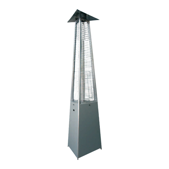
- Page 3 FA L O ’ LEGENDA: 1) pomello di fissaggio, 2) parabola di copertura, 3) testa scambiatore, 4) cilindro rete (optional), 5) montante struttura, 6) griglia di protezione, 7) tubo in vetro, 8) vite di fissaggio, 9) bruciatore, 10) manopola accensione/regolazione, 11) portapile, 12) centralina (Mod. telecomando), 13) base sostegno bombola, 14) pannello laterale, 15) pannello copri comandi, 16) pomello di fissaggio, 17) fessura display centralina (Mod.
- Page 4 FA L O ’ Fig.1 Fig.2 raggio azione 3m range of action 3m L1 600 L2 640...
- Page 5 FA L O ’ Fig.4 1,5Volt 1,5Volt 1,5Volt torcia stilo ministilo Fig.5 Fig.6...
- Page 6 FA L O ’ Fig.7 Fig.8 Fig.9...
- Page 7 FA L O ’ Fig.10 Fig.11 Fig.12...
- Page 8 FA L O ’ ITA - MONTAGGIO KIT ANTIVENTO Fig.13 UK - HURRICANE KIT ASSEMBLY DE - MONTAGE GEGEN WIND ITA - MANUTENZIONE TUBO Fig.14 UK - TUBE MAINTENANCE DE - WARTUNG TUBE optional optional...
- Page 9 FA L O ’ Fig.15 on/off centralina control unit on MAX Fig.16 ITA - DISPOSITIVO DI SICUREZZA ANTIRIBALTAMENTO (se presente) UK - DUNP-SWITCH SAFETY DEVICE (when mounted) DE - SAFETY DEVICE ANTI-KIPPEN (bei montage)
- Page 10 FA L O ʼ ITALKERO Srl - v. Lumumba, 2 - 41100 - Modena - ITALY - MADE IN ITALY - H kW I kW L g/h M Ø mm N Ø mm O G30 mbar P G31 mbar 1,65...
- Page 11 FA L O ’ Tab. 1 Tab. 2...
-
Page 12: The Remote Control
FA L O ’ Tab. 1 Tab. 2... -
Page 13: Table Of Contents
FA L O ’ ITA - REGOLATORE PER GERMANIA (50 mbar) UK - GAS GOVERNOR FOR GERMANY (50 mbar) DE - DRUCKGAS REGLER FUR DEUTSCHLAND (50 mbar) - IT - Indice IL TELECOMANDO pag. 8 DESCRIZIONE GENERALE pag. MONTAGGIO pag. MESSA IN FUNZIONE pag. - Page 14 FA L O ’ CONSERVARE ACCURATAMENTE QUESTO LIBRETTO PER TUTTA LA VITA DELL’APPA- RECCHIO E RICHIEDERNE UNO NUOVO IN CASO DI DISTRUZIONE O SMARRIMENTO! IMPORTANTE! QUALORA LE PARTI RISULTINO DANNEGGIATE NON PROCEDERE ASSOLUTAMENTE CON L’ASSEMBLAGGIO! IMPORTANTE! Questo apparecchio dovrà essere installato in accordo con i Regolamenti, Leggi e Norme in vigore nel Paese dove sarà...
-
Page 15: Descrizione Generale
FA L O ’ DESCRIZIONE GENERALE Per il suo particolare tipo di funzionamento ad irraggiamento diretto e riflesso, quest’apparec- chio permette di riscaldare una superficie di circa 20/25 m (Fig.2), naturalmente in ambienti con un buon flusso di aria fresca come ad esempio: terrazze, pergolati, ristoranti, bar, birrerie e installazioni all’aperto (giardini, marciapiedi, ecc). - Page 16 FA L O ’ La parte terminale filettata ossia l’adattatore (Fig.9: 4) consente diversi tipi di allacciamento: IMPORTANTE! esistono due tipologie di adattatori uno sinistrorso (SVIZZERA, AUSTRIA, GERMANIA e LUSSEMBURGO) ed uno destrorso (per tutti gli altri Paesi). CASO A (Fig.9: A) 1/4” gas sinistrorso: montare il tubo in gomma (1), munito di apposito rac- cordo filettato (A CORREDO), soluzione valida per i Paesi di SVIZZERA, AUSTRIA, GERMA- NIA e LUSSEMBURGO.
-
Page 17: Messa In Funzione
FA L O ’ quindi, la tipologia corretta come specificato e illustrato nelle Tab. 1 o 2. 7 - Verificare che il tipo di gas e la pressione di alimentazione corrispondano a quelli di targa (vedi Tabella), montare se necessario il riduttore/regolatore di pressione (NON a corredo). 8 - Acquistare a parte, il raccordo ed il tubo di collegamento, del tipo e materiale adatti alle Normative vigenti nel paese di utilizzo. -
Page 18: Il Telecomando
FA L O ’ Accensione mod. MANUALE Sequenza regolazione, ruotando la manopola: OFF, scintilla ON, MIN e MAX; 1 - Verificare che la manopola di accensione/regolazione (Fig.3: 10) sia in posizione di spento OFF (Fig.5: 1) e aprire il rubinetto di alimentazione gas. 2 - Spingere e ruotare in senso antiorario (Fig.5) la manopola di accensione/regolazione, in questo modo partirà... -
Page 19: Spegnimento
FA L O ’ SPEGNIMENTO A - Mod. MANUALE: 1 - Rimuovere la copertura laterale (Fig.3: 15). 2 - Ruotare in senso orario la manopola di comando, riportandola sulla posizione "0" (Fig.5: 1). 3 - Rimontare correttamente la copertura laterale con procedimento inverso. B - Mod. -
Page 20: Rimessaggio
FA L O ’ Costruttore non può essere considerato responsabile di eventuali danni a persone o cose deri- vanti da questa o altre manomissioni. L’apparecchio perciò deve essere assemblato SOLO dal Costruttore ed ordinato dall’utente direttamente per il tipo di gas che verrà utilizzato per il fun- zionamento. -
Page 21: Eventuali Anomalie E Rimedi
FA L O ’ EVENTUALI ANOMALIE E RIMEDI: con telecomando. - Page 22 FA L O ’ EVENTUALI ANOMALIE E RIMEDI: comandi manuali. *Rottura tubo di vetro Le caratteristiche tecniche del tubo di vetro sono particolari e tali da consentire la resistenza a shock termici dovuti a normali sbalzi di temperatura, pioggia o umidità. Nonostante la scelta di questo materiale (Borosilicato), possono però...
- Page 23 FA L O ’ - UK - Contents THE REMOTE CONTROL page 8 GENERAL DESCRIPTION page 21 ASSEMBLY page 21 START-UP page 23 SWITCH-OFF page 25 MAINTENANCE page 25 STORAGE page 26 WARRANTY page 26 TROUBLESHOOTING page 27...
- Page 24 FA L O ’ CAREFULLY LOOK AFTER THIS BOOKLET FOR THE ENTIRE LIFE OF THE APPLIANCE AND REQUEST A NEW ONE IN CASE OF DAMAGE OR LOSS! IMPORTANT! SHOULD THE PARTS BE DAMAGED, DO NOT GO AHEAD WITH ASSEMBLY! IMPORTANT! This appliance must be installed in compliance with the Regulations, Laws and Standards applicable in the Country of use.
-
Page 25: General Description
FA L O ’ GENERAL DESCRIPTION Due to its specific type of operation with direct and reflected radiation, this appliance permits heating a surface of around 20/25 m2 (Fig. 2), naturally in environments with good fresh air ven- tilation, for example: terraces, pergolas, restaurants, cafés and open-air installations (gardens, pavements, etc). - Page 26 FA L O ’ ASSEMBLY OPERATIONS (MOBILE type with LPG tank): Before starting assembly operations, remove any guards. 1 – Delicately place the structure on the ground and fit the cover dish (Fig. 3: 2). 2 – Remove the side panels (Fig. 3: 14, 15) and position the tank on the base plate (Fig. 3: 13). 3 –...
-
Page 27: Start-Up
FA L O ’ 6 – Before making the connection, check to see whether the gas diaphragm (Fig. 9: 5) needs fit- ting on the inlet connection (Fig. 9: 4) (solution valid for SWITZERLAND, AUSTRIA, GERMANY and LUXEMBOURG - see Tab. 1 or 2). IMPORTANT! DO NOT FIT the diaphragm on appliances fuelled with gas G30/G31 at 29÷37 mbar. - Page 28 FA L O ’ IMPORTANT! WHEN FIRST STARTED – IN THE OPEN AIR OR WELL-VENTILATED ENVIRON- MENT – THE APPLIANCE COULD GIVE OFF VAPOURS OR SMELLS FOR A SHORT TIME. Ignition – MANUAL mod. Regulation sequence, turn knob: OFF, spark ON, MIN and MAX; 1 –...
-
Page 29: Switch-Off
FA L O ’ SWITCHING OFF A - MANUAL mod.: 1 – Remove the side cover (Fig. 3: 15). 2 – Turn the control knob clockwise, returning this to position "0" (Fig. 5: 1). 3 – Correctly fit the side cover back on in reverse sequence. B –... -
Page 30: Storage
FA L O ’ STORAGE If the appliance is not used for a long time (change of season or other reasons), follow the instructions below: - Store the appliance in a dry place, protected against any possible damage. - ALWAYS cover the burner unit and base to avoid obstructions (cobwebs, dust) or damage (denting, weather conditions, etc.). -
Page 31: Troubleshooting
FA L O ’ TROUBLESHOOTING: with remote control. - Page 32 FA L O ’ TROUBLESHOOTING: manual controls. * Glass pipe breakage The technical features of the glass pipe are particular and such as to permit resistance to ther- mal shocks caused by normal temperature fluctuations, rain or damp. Despite the choice of this material (Borosilicate), sudden pipe breakages can occur as a result of particular weather conditions and/or excessively concentrated temperature fluctuations.
- Page 33 FA L O ’ - DE - Inhaltsverzeichnis FERNBEDIENUNG Seite 8 ALLGEMEINE BESCHREIBUNG Seite 31 MONTAGE Seite 31 INBETRIEBSETZUNG Seite 33 AUSSCHALTUNG Seite 35 WARTUNG Seite 35 AUFBEWAHRUNG Seite 36 GARANTIE Seite 36 EVENTUELLE STÖRUNGEN UND ABHILFEN Seite 37...
- Page 34 FA L O ’ DIESES HANDBUCH FÜR DIE GANZE LEBENSDAUER DES GERÄTS AUFBEWAHREN UND EIN NEUES ANFORDERN, FALLS ES ZERSTÖRT WERDEN ODER VERLOREN GEHEN SOLLTE! WICHTIG! FALLS DIE BAUTEILE BESCHÄDIGT SEIN SOLLTEN, KEINESFALLS DIE ZUSAMMENFÜGUNG VORNEHMEN! WICHTIG! Dieses Gerät ist in Übereinstimmung mit den im Bestimmungsland geltenden Regelungen, Gesetzen und Vorschriften aufzustellen.
-
Page 35: Allgemeine Beschreibung
FA L O ’ WICHTIG! Bevor man mit den Montagevorgängen beginnt, überprüfen, dass alle Gerätbauteile für den Gastyp und den Druck vorbereitet sind, die für den Gebrauch laut geltender Vorschriften des Bestimmungslandes vorgesehen sind. ALLGEMEINE BESCHREIBUNG Aufgrund seiner Betriebsart mit direkter und reflektierter Strahlung erlaubt es dieses Gerät, eine Fläche von circa 20/25 m2 (Abb.2) zu erwärmen, dies natürlich in Umfeldern mit einem guten Frischluftzufluss wie zum Beispiel: Terrassen, Lauben, Restaurants, Cafés, Bierstuben und Installationen im Freien (Gärten, Fußwege, usw). - Page 36 FA L O ’ MONTAGEPHASEN (BEWEGLICHER Typ mit Gasflasche, Flüssiggas): Vor dem Beginn der Montage, eventuelle Schutzelemente beseitigen. 1 – Die Struktur vorsichtig auf den Boden stellen und den Abdeckschirm anbringen (Abb.3: 2). 2 – Die seitlichen Tafeln entfernen (Abb.3: 14, 15) und die Gasflasche auf die Stützfläche stellen (Abb.3: 13).
-
Page 37: Inbetriebsetzung
FA L O ’ 2 – Das Gerät platzieren, wobei die Position des Versorgungsschlauches zu berücksichtigen ist, und die seitlichen Tafeln entfernen (Abb. 3: 14, 15). 3 – Am Boden die Position der Befestigungslöcher markieren. 4 – Die Struktur mit für die Art des Fußbodens geeigneten Dübeln (Abb. 11:1, NICHT mitgeliefert) am Boden befestigen und dazu die an der Gasflaschenstützfläche vorbereiteten Löcher (Abb. - Page 38 FA L O ’ - Sollte die Sparflamme durch Gasmangel ausgehen, so wird die Gaszufuhr abgeschlossen (z.B. wenn die Gasflasche leer ist). - In beiden Fällen sollten Sie eine Weile warten, bevor Sie das Gerät wieder in Betrieb nehmen und danach die Schritte 1 und 2 wiederholen. - Versuchen Sie nicht, das Gerät immer wieder anzuzünden.
-
Page 39: Ausschaltung
FA L O ’ Die Einstellung der Leistung kann auch während des Gerätbetriebs erfolgen: - MANUELLES Modell (Abb. 5): Anhand des Zünd-/Einstellknopfes. - Modell mit FERNBEDIENUNG (Abb. 6): Anhand der Fernbedienung oder mit dem Knopf an der Steuereinheit. WICHTIG! Für den Betrieb des Geräts mit Flüssiggas im Freien und bei Temperaturen von weniger als 2°C empfiehlt es sich, Propangas zu verwenden. -
Page 40: Aufbewahrung
FA L O ’ 5 – Die neue Düse (stets für dieselbe Gasart) einsetzen und vorsichtig bis zum Anschlag hineinschrauben. 6 – Alles auf umgekehrte Weise wieder zusammenfügen. WICHTIG! Das Gerät darf auf KEINE Weise von Methan auf Flüssiggas oder umgekehrt umgerüstet werden. -
Page 41: Eventuelle Störungen Und Abhilfen
FA L O ’ EVENTUELLE STÖRUNGEN UND ABHILFEN: mit Fernbedienung. - Page 42 FA L O ’ EVENTUELLE STÖRUNGEN UND ABHILFEN: mit manuellen Bedienelementen. *Bruch der Glasröhre Die Glasröhre haben besondere technischen Merkmale, dank derer sie den, durch normale Temperaturschwankungen, Regen und Feuchtigkeit verursachten Temperaturschocks wider- stehen. Obwohl dieses Material (Borsilikat) gewählt wurde, können aber trotzdem plötzliche Brüche der Glasröhre aufgrund besonderer klimatischer Ereignisse und/oder zu starker Temperaturschwankungen auftreten.
- Page 43 FA L O ’ NOTE...
Need help?
Do you have a question about the FALO 8 kW and is the answer not in the manual?
Questions and answers