Table of Contents
Advertisement
Advertisement
Table of Contents

Related Manuals for BMS HELI-CODER 4

Summary of Contents for BMS HELI-CODER 4
- Page 1 HELI-CODER™ 4 TRANSMITTER Operation Manual Doc. No. 6051452100 Rev.C1...
- Page 2 (electronic, mechanical, photocopying, recording or otherwise), whether in whole or in part, without BMS prior written agreement. This printed document is uncontrolled and is for reference only. Users are to verify that this is the latest approved version.
-
Page 3: Conventions Used In This Manual
RF power loss at the operating frequencies of this system. FOR ALL BMS TRANSMITTERS – Operation of a BMS transmitter product generally requires a license. It is the responsibility of the user to obtain all required operating licenses. - Page 4 PAGE INTENTIONALLY LEFT BLANK Broadcast Microwave Services, Inc.
-
Page 5: Table Of Contents
Control ................................12 TRANSMITTER OPERATION ........................13 Operating the Transmitter with the DLC50 Control Panel ..............13 DLC50 Menu Structure ........................... 14 BMS Geo-Point™ System..........................16 Geo-Point System Description ....................... 16 Enabling Geo-Point™ ..........................16 SOFTWARE INSTALLATION ........................17 ACCESSORIES .............................. 18 ADDITIONAL REFERENCES ........................ - Page 6 List of Figures Figure 1. Heli-Coder 4 Transmitter ..........................4 Figure 2 HC4 Front Panel Labels ..........................3 Figure 3 Transmitter mounting bracket ........................8 Figure 4 HC4 positioned in aircraft mounting bracket ....................8 Figure 5 HC4 Outline Drawing ........................... 9 Figure 6 CT-A-MP HC4 Mounting Plate - Dimensioned Drawing ................
-
Page 7: Introduction
Transmitter controlled by a DLC50 Downlink Control Panel. BMS offers a wide selection of airborne products to meet the video and data requirements of today’s real world applications. The Heli-Coder™ 4 (HC4) together with the DLC50 controller provides a simple, powerful solution containing everything needed for high-quality, reliable transmission. -
Page 8: Safety
RF field, exposure is limited by transmission duty cycles, the flight or testing ends, hang up the cell phone, put up the walkie-talkie, etc. BMS recommends that operators use the uncontrolled exposure category from OET 65 as it applies to an uncontrolled environment; a maximum power density limit of 1mW/cm². -
Page 9: Table 1 Mpe Per Fcc Oet65 (1.5 Ghz To 100 Ghz)
Switch off supplies before removing covers or disconnecting any RF cables, and before inspecting damaged cables or antennas. d) BMS recommends returning the HC4 to the factory for service or repair. In addition you can limit your exposure by raising awareness and using some common sense rules. -
Page 10: Product Definition
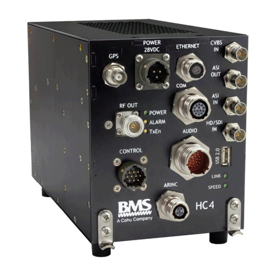
Heli-Coder 4 Transmitter Operation Manual | Doc. No. 6051452100 Rev. C 3 PRODUCT DEFINITION Figure 1. Heli-Coder 4 Transmitter Table 2. Product connector descriptions in Figure 1 GPS Antenna Input USB 2.0 port 28VDC Power Mounting bracket (x2) Ethernet Status Indicators: Yellow SPEED LED:... -
Page 11: Product Specifications
Heli-Coder 4 Transmitter Operation Manual | Doc. No. 6051452100 Rev. C Product Specifications Frequency 6425-6525 MHz Channel Bandwidth 6/7/8 MHz RF Output Power 5W/10 W switchable COFDM 2k QPSK, 16/64 QAM Modulation FEC 1/2, 2/3, 3/4, 5/6, 7/8 ... -
Page 12: Connectors And Pinouts
Heli-Coder 4 Transmitter Operation Manual | Doc. No. 6051452100 Rev. C 4 CONNECTORS AND PINOUTS Figure 2 HC4 Front Panel Labels Table 3. HC4 connectors GPS In (with optional DC Bias Out) TNC(f), 50 ohm Power In Souriau 3-pin male 851-02R12-3P50... -
Page 13: Table 2. Product Connector Descriptions In Figure 1
Heli-Coder 4 Transmitter Operation Manual | Doc. No. 6051452100 Rev. C Table 4. Connector pin outs GPS ANTENNA INPUT TNC CONN (FEMALE) 50 OHM Provides variable DC SIGNAL bias or none. SHIELDING GND GPS J1 610006040, TNC(f), 50 ohm 3-pin SOURIAU (m) - Page 14 Heli-Coder 4 Transmitter Operation Manual | Doc. No. 6051452100 Rev. C RF OUTPUT N- CONN(FEMALE) 50 OHM UP TO 10W RF SIGNAL OUT COFDM SHIELDING GND RF OUTPUTJ5 AUDIO AUDIO 1 L GND AUDIO 1 L+ AUDIO 1 L- AUDIO 1 R GND...
- Page 15 Heli-Coder 4 Transmitter Operation Manual | Doc. No. 6051452100 Rev. C COMPOSITE VIDEO INPUT BNC CONN(FEMALE) 75 OHM May be NTSC or PAL SIGNAL SHIELDING CVBS INPUT J9 GROUND BNC(f), 75 ohm ASI SERIAL DATA OUTPUT BNC CONN(FEMALE) 75 OHM...
-
Page 16: Installation
The HC4 may be ordered with the HC4-CONN-KIT which contains all mating connectors except those locally available (BNC, N, and USB). Alternatively BMS will supply a partially assembled wiring harness upon order request. -
Page 17: Fasteners
Mounting the Transmitter The HC4 transmitter should be mounted in aircraft or other craft using the BMS-supplied mounting bracket (BMS P/N 4414414000). The transmitter/bracket assembly must have adequate space above and below the unit to allow free air flow. Three thermostatically controlled fans contained within the HC4 chassis keep the unit at operating temperature. -
Page 18: Figure 5 Hc4 Outline Drawing
Heli-Coder 4 Transmitter Operation Manual | Doc. No. 6051452100 Rev. C Figure 5 HC4 Outline Drawing Broadcast Microwave Services, Inc. -
Page 19: Figure 6 Ct-A-Mp Hc4 Mounting Plate - Dimensioned Drawing
Heli-Coder 4 Transmitter Operation Manual | Doc. No. 6051452100 Rev. C 0.98" (2.5 cm) M6 Threaded 9.09" Hole (4 plcs) (23.1 cm) 11.18" (28.4 cm) 3.94" 5.12" (10.0 cm) (13 cm) Figure 6 CT-A-MP HC4 Mounting Plate - Dimensioned Drawing... -
Page 20: Wiring Connections And Signal Interfaces
Hook-Up Diagram for HC4 System” shown later in this document. Also reference section 16 of this manual titled “CONNECTION AND WIRING DIAGRAMS” during installation for detail related to a typical installation. Contact BMS regarding issues related to custom or modified installations if applicable. Additional service or fees may apply. -
Page 21: Data Wayside Input
IP packet (either TCP or UDP) and convert that data into a format to be sent in the MPEG transport stream. A companion receiver (like the BMS SPRITE-PRO Series) recovers the packets and ports them out of an Ethernet connection. -
Page 22: Transmitter Operation
Operating the Transmitter with the DLC50 Control Panel The HC4 is designed for standard operation via a BMS DLC50 Control Panel. After wiring the transmitter according to the wiring diagram shown in the wiring and connection section the transmitter may be turned on via the power switch (PWR) located on the front face of the DLC50 Control Panel. -
Page 23: Dlc50 Menu Structure
Heli-Coder 4 Transmitter Operation Manual | Doc. No. 6051452100 Rev. C DLC50 Menu Structure* Figure 9 DLC50 Commands For full DLC50 operation see BMS document 6051439500 "DLC50 Operating Manual" Broadcast Microwave Services, Inc. -
Page 24: Figure 10 Dlc50 Outline
Heli-Coder 4 Transmitter Operation Manual | Doc. No. 6051452100 Rev. C Figure 10 DLC50 Outline Broadcast Microwave Services, Inc. -
Page 25: Bms Geo-Point™ System
The SP info must be added to the NMEA stream in the TLL word (Target Lat/Long) position. The RX site will track by reading the aircraft position LAT/LONG from the NMEA stream while Geo-Pont enabled display, (e.g. a BMS CVIII+, or CVIII+-HD) will use the TLL info to develop the range/distance report for the Geo-Point display overlay. -
Page 26: Software Installation
Heli-Coder 4 Transmitter Operation Manual | Doc. No. 6051452100 Rev. C 8 SOFTWARE INSTALLATION The DLC50 and HC4 both come completely loaded with the software required to operate the unit. However field installation of software can easily be accomplished by the user in order to Update, Upgrade, or even reinstall the system software. -
Page 27: Accessories
Heli-Coder 4 Transmitter Operation Manual | Doc. No. 6051452100 Rev. C 9 ACCESSORIES Item Description Part Number CT-A-MP Mounting Plate Mounting plate for transmitter 4414414000 Kit; Mating Connectors for HC4 Includes all PTO type connectors required for full HC4 installation. -
Page 28: Regulatory
Heli-Coder 4 Transmitter Operation Manual | Doc. No. 6051452100 Rev. C 11 REGULATORY 11.1 Electromagnetic Compliance CE marked in accordance with EU Low Voltage and EMC Directives EN55022 EN55024 11.2 The HC4 is an intentional radiator and is authorized by the Federal Communications Commission (FCC) to comply with the following parts of CFR 47 (grant pending);... -
Page 29: Preventive Maintenance
13 REPAIR SERVICE AND WARRANTY BMS warrants that, at time of delivery, this product will be free from defects in materials and workmanship, provided the equipment or system is installed, operated and maintained in accordance with the Operation and Maintenance manual or such other BMS documentation as may be applicable. -
Page 30: Customer Service
Heli-Coder 4 Transmitter Operation Manual | Doc. No. 6051452100 Rev. C Figure 11 Product Label Defective components under BMS warranty will be repaired/replaced promptly at the discretion of BMS. Items no longer under warranty will require a PO before repairs can proceed. -
Page 31: Glossary
Heli-Coder 4 Transmitter Operation Manual | Doc. No. 6051452100 Rev. C 14 GLOSSARY Advanced Encryption System. Optional encryption system available for signal privacy Analog Transmission Frequency Modulated (FM) method of sending information with radio waves. An older, dependable method of transmission. (See Digital Transmission) - Page 32 Heli-Coder 4 Transmitter Operation Manual | Doc. No. 6051452100 Rev. C Key Length Value. A method of encoding data into video streams. Defined in standard SMPTE 336M-2007 Multipath The radio wave propagation phenomenon that results in the transmitted signals ft. reaching the receiving antenna by two or more paths. This condition is not desirable and usually results in signal fading and interference.
-
Page 33: Connection And Wiring Diagrams
Heli-Coder 4 Transmitter Operation Manual | Doc. No. 6051452100 Rev. C 15 CONNECTION AND WIRING DIAGRAMS This section contains system and hook-up wiring diagrams. Broadcast Microwave Services, Inc. -
Page 34: Figure 12 Typical Airborne Installation Diagram (Without Taa-101 Antenna Actuator)
Heli-Coder 4 Transmitter Operation Manual | Doc. No. 6051452100 Rev. C Figure 12 Typical airborne installation diagram (without TAA-101 Antenna Actuator) Broadcast Microwave Services, Inc. -
Page 35: Figure 13 Wire Hook-Up Diagram For Hc4 System (Without Taa-101 Antenna Actuator)
Heli-Coder 4 Transmitter Operation Manual | Doc. No. 6051452100 Rev. C Figure 13 Wire Hook-Up Diagram for HC4 System (without TAA-101 Antenna Actuator) Broadcast Microwave Services, Inc. -
Page 36: Figure 14 Typical Airborne Installation Diagram (Including Taa-101 Antenna Actuator)
Heli-Coder 4 Transmitter Operation Manual | Doc. No. 6051452100 Rev. C Figure 14 Typical airborne installation diagram (including TAA-101 Antenna Actuator) Broadcast Microwave Services, Inc. -
Page 37: Figure 15 Wire Hook-Up Diagram For Hc4 System (Including Taa-101 Antenna Actuator)
Heli-Coder 4 Transmitter Operation Manual | Doc. No. 6051452100 Rev. C Figure 15 Wire Hook-Up Diagram for HC4 System (including TAA-101 Antenna Actuator) Broadcast Microwave Services, Inc. - Page 38 Heli-Coder 4 Transmitter Operation Manual | Doc. No. 6051452100 Rev. C COFDM Characteristics The main COFDM modulation parameters are: Number of sub-carriers (about 2000 for DVB-T) Guard interval (GI) duration between COFDM symbols Constellation scheme used for individual sub-carrier modulation ...
- Page 39 Heli-Coder 4 Transmitter Operation Manual | Doc. No. 6051452100 Rev. C The following table summarizes the results of the 4 possible guard interval values: Guard Interval Guard Interval Maximum echoes Maximum transmission Ratio Duration (us) dispersion (km) distance (km) 1/32...
Need help?
Do you have a question about the HELI-CODER 4 and is the answer not in the manual?
Questions and answers