Sign In
Upload
Manuals
Brands
BMS Manuals
Transmitter
HELI-CODER 4
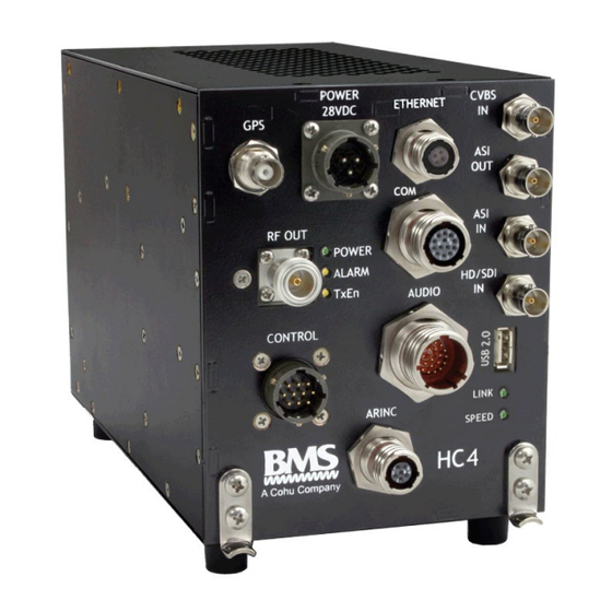
User Manuals: BMS HELI-CODER 4 Airborne Transmitter
Manuals and User Guides for BMS HELI-CODER 4 Airborne Transmitter. We have
1
BMS HELI-CODER 4 Airborne Transmitter manual available for free PDF download: Operation Manual
BMS HELI-CODER 4 Operation Manual (39 pages)
Brand:
BMS
| Category:
Transmitter
| Size: 3 MB
Table of Contents
Conventions Used in this Manual
3
Table of Contents
5
1 Introduction
7
2 Safety
8
Table 1 MPE Per FCC OET65 (1.5 Ghz to 100 Ghz)
9
3 Product Definition
10
Figure 1. Heli-Coder 4 Transmitter
10
Product Specifications
11
Model Information
11
4 Connectors and Pinouts
12
Figure 2 HC4 Front Panel Labels
12
Table 3. HC4 Connectors
12
Table 2. Product Connector Descriptions in Figure 1
13
Table 4. Connector Pin Outs
13
5 Installation
16
Locating the Components
16
Table 5. HC4 Component Placement Planning
16
Fasteners
17
Mounting the Transmitter
17
Figure 3 Transmitter Mounting Bracket
17
Figure 4 HC4 Positioned in Aircraft Mounting Bracket
17
Figure 5 HC4 Outline Drawing
18
Figure 6 CT-A-MP HC4 Mounting Plate - Dimensioned Drawing
19
Wiring Connections and Signal Interfaces
20
Power Input (J2)
20
Radio Frequency Output (RF Out) (J5)
20
Serial Digital Video Input (J12)
20
Composite Video (CVBS) Input (J9)
20
ASI Input
20
ASI Output
20
Audio Input
20
Gps
20
Data Wayside Input
21
KLV Data
21
Auxiliary Data
21
Ethernet
21
Usb
21
Arinc
21
Control
21
6 Transmitter Operation
22
Operating the Transmitter with the DLC50 Control Panel
22
Figure 7 DLC50-A AVIONICS CONTROL PANEL (FRONT)
22
Figure 8 DLC50-A AVIONICS CONTROL PANEL (BACK)
22
DLC50 Menu Structure
23
Figure 9 DLC50 Commands
23
Figure 10 DLC50 Outline
24
7 BMS Geo-Point™ System
25
Geo-Point System Description
25
Enabling Geo-Point
25
8 Software Installation
26
9 Accessories
27
10 Additional References
27
11 Regulatory
28
Electromagnetic Compliance
28
Fcc
28
Environmental Qualifications
28
12 Preventive Maintenance
29
Maintenance Schedule
29
Maintenance Procedures
29
Spare Parts
29
13 Repair Service and Warranty
29
Customer Service
30
Figure 11 Product Label
30
14 Glossary
31
15 Connection and Wiring Diagrams
33
Figure 12 Typical Airborne Installation Diagram (Without TAA-101 Antenna Actuator)
34
Figure 13 Wire Hook-Up Diagram for HC4 System (Without TAA-101 Antenna Actuator)
35
Figure 14 Typical Airborne Installation Diagram (Including TAA-101 Antenna Actuator)
36
Figure 15 Wire Hook-Up Diagram for HC4 System (Including TAA-101 Antenna Actuator)
37
Advertisement
Advertisement
Related Products
BMS 4748905
BMS 4748910
BMS 4748915
BMS 4748920
BMS 11.2531.000
BMS CT6020HD
BMS NT5723SDHD
BMS Truck-Coder II
BMS Categories
Microscope
Test Equipment
Utility Vehicle
Transmitter
Measuring Instruments
More BMS Manuals
Login
Sign In
OR
Sign in with Facebook
Sign in with Google
Upload manual
Upload from disk
Upload from URL