Table of Contents
Advertisement
Quick Links
2000 Series ICC Module IU2080
Indicating Circuit Controller
I
NSTALLASJON
N
I
NSTALLATIONS
S
I
NSTALLATIONSVEJLEDNING
DK
GB
G
D
ENERAL
ESCRIPTION
The IU2080 provides an interface between the two wire multiplexed ring circuit and local
supply sounders and strobes with their associated user external power supply (24 V).
The external power supply provides the power to drive the sounders and strobes. A
number of devices totalling up to 3 A can be connected to the sounder spur (750 mA in
applications requiring AFNOR approvals).
The ICC monitors the local power supply for a low voltage condition and the external
fault relay contacts (via fault + -ve) for an open condition. An end-of-line (EOL) resistor
is used to insure that the local supply loop is intact. The ICC monitors for loop shorts as
well as for loop open circuits via this resistor. Moreover, the ICC can provide a means
for EOL monitoring via a Z-style connection back to the ICC itself.
I
NDICATORS
The IU2080 contains a red LED that will light when the relay is in a position to cause the
sounders and sirens to be energized. The green LED indicates that the external power
supply voltage is present and greater than approximately 8 V.
I
NSTALLATION
Please refer to the wiring diagrams for the proper wiring of the indicating circuit
controller.
[part number]
-
S
OCH
ERVICEHANDLEDNING
S
IGNALISATSIOONIAHELA KONTROLLER
EST
P
AIGALDUS
S
IGNALIZATORIŲ KONTROLĖS MODULIS
LT
Į
RENGIMO IR APTARNAVIMO INSTRUKCIJA
I
NDIKĀCIJAS ĶĒDES KONTROLLERS
LV
U
S
ETTING THE
Use a screwdriver to adjust the two rotary switches on the unit. Set the left rotary switch
(MSB: 0-12) for the 10's and 100's digit, and the right rotary switch (LSB) for the 0-9
digit. Do not set the address to either 0 or 129. This will not produce a response from
the unit.
T
D
ECHNICAL
Operating voltage................................................................................................... 17-28 V
Total standby current ........................................................................................... < 350 µA
Maximum loop alarm current ............................................................................... < 3.5 mA
End of line resistor value..............................................................................10 k ¼ W, 5%
Bell loop impedances at 24 V:
Short circuit.......................................................................................................< 3.3 k
Quiescent ..............................................................................................3.3 k – 13.0 k
Open circuit ....................................................................................................< 13.0 k
Local power supply, low voltage detection:
24 V supply.................................................................................................... < 20.4 V
Local supply current (standby) .........................................................< 11.0 mA @ 24 VDC
Local supply current (alarm).............................................................< 72.0 mA @ 24 VDC
Supervisory voltage.................................................................... approx. 2.2 VDC inverted
Fuse rating .................................................................................................................... 3 A
© 2001 Interlogix BV
All rights reserved
WWW.UKPANELS.COM
-
JA HOOLDUSJUHEND
ZSTĀDĪŠANAS INSTRUKCIJA
Installation Instructions
A
DDRESS
ATA
(at the communication loop terminals)
.
.
.
.
.
.
(< 200 µA typical)
plus bell loop load current
Advertisement
Table of Contents

Related Manuals for Aritech IU2080


Summary of Contents for Aritech IU2080
- Page 1 NDICATORS Maximum loop alarm current ................< 3.5 mA The IU2080 contains a red LED that will light when the relay is in a position to cause the End of line resistor value................10 k ¼ W, 5% sounders and sirens to be energized. The green LED indicates that the external power Bell loop impedances at 24 V: supply voltage is present and greater than approximately 8 V.
- Page 2 Figure Style Y operation without power supply trouble relay Joonis Y tüüpi talitlus ilma toiteallika rikkereleeta Figure Style Z operation without power supply trouble relay Joonis Z tüüpi talitlus ilma toiteallika rikkereleeta Connect the indicating circuit for 24 VDC application without the fault contact Ühendage 24 V alalisvooluseadmete signalisatsiooniahel ilma rikkereleeta.
- Page 3 WWW.UKPANELS.COM...
- Page 4 Figure : Fault signal indication with open collector driver Joonis : Rikkesignaali näitamine avatud kollektoridraiveriga Connect the fault signal terminals as shown if the open collector transistor is Ühendage rikkesignaali klemmid nagu joonisel näidatud, kui kasutatakse used. The transistor has to be in the “on” condition under normal operation. If avatud kollektoriga transistorit.
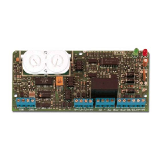
- Page 5 Figure : Physical layout of the ICC board Joonis : ICC plaadi füüsiline paigutus Address, Fuse Aadress, Sulavkaitse Figur : Fysisk utlegg av ICC-kortet Paveikslas : Fizinis SKM plokštės elementų išdėstymas Addresse, Sikring Adresas, Saugiklis : indikācijas ķēdes kontrollera plates shēmas izkārtojums Figur : Fysisk uppbyggnad av LÖE-kretskortet Zīmējums...
Need help?
Do you have a question about the IU2080 and is the answer not in the manual?
Questions and answers