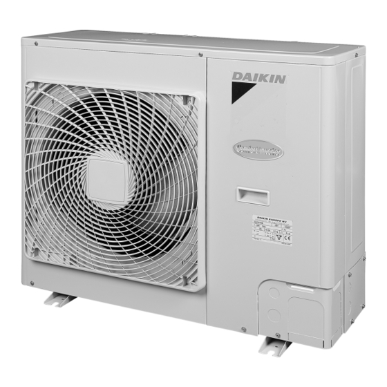
Summary of Contents for Daikin RZQ71B7V3B
-
Page 1: Installation Manual
INSTALLATION MANUAL Split System air conditioners RZQ71B7V3B RZQ100B7V3B RZQ125B7V3B... - Page 2 B 2 B 2 D 2 D 2 D 2 D 2 L 1 L 1 B 1 B 1 L 2 L 2 D 1 D 1 B 2 B 2 D 2 D 2 D 2 D 2 L 1 L 1 B 1 B 1 L 2 L 2...
- Page 3 3PW14488-3C...
-
Page 4: Table Of Contents
Improper installation work may result in accidents due OTHER DAMAGE TO THE EQUIPMENT. BE SURE ONLY to fall of equipment. TO USE ACCESSORIES MADE BY DAIKIN WHICH ARE Make certain that all electrical work is carried out by SPECIFICALLY DESIGNED FOR USE WITH THE qualified personnel according to the local laws and... -
Page 5: Before Installation
EFORE INSTALLATION CAUTION Ground the air conditioner. Grounding resistance should be according to national Since design pressure is 4.0 MPa or 40 bar, pipes of larger regulations wall thickness may be required. Refer to paragraph Do not connect the earth wire to gas or "Selection of piping material"... -
Page 6: Selecting Installation Site
When installing the unit in a place frequently exposed to snow, ELECTING INSTALLATION SITE pay special attention to the following: Select an installation site where the following conditions are Elevate the foundation as high as possible. satisfied and that meets with your customer's approval. Remove the rear suction grille to prevent snow from Places which are well-ventilated. -
Page 7: Installation Servicing Space
Drain pipe disposal (C) In case of multiple-row installation (for roof top use, etc.) In case of installing one unit per row. If drain pipe disposal from the outdoor unit causes trouble, provide the drain piping by using of the drain socket (optional). NSTALLATION SERVICING SPACE ≥50 The numerical figures used in here represent the dimensions for the... - Page 8 Selection of piping material Allowable pipe length and height difference Construction material: phosphoric acid deoxidized seamless See the table below concerning lengths and heights. Refer to figures copper for refrigerant. 2, 3, and 5. Assume that the longest line in the figure corresponds with the actual longest pipe, and the highest unit in the figure Temper grade: use piping with temper grade in function of the corresponds with the actual highest unit.
-
Page 9: Precautions On Refrigerant Piping
Existing or pre-installed piping can be used Precautions to be taken. (For details, refer to the manual attached to branch piping kit.) Piping must comply with the criteria below. Install the branch pipes horizontally. (Maximum inclination: • Pipe diameter must comply with the limitations as indicated in 30°... -
Page 10: Precautions When Connecting Field Piping And Regarding Insulation
Preventing foreign objects from entering Plug the pipe through-holes with putty or insulating material (procured locally) to stop up all gaps, as shown in the figure. Closing direction Liquid side Gas side Cautions for handling the valve cover Putty or insulating material (produced locally) The valve cover is sealed where indicated by the arrow. -
Page 11: Evacuating
Cautions for brazing Be sure to carry out a nitrogen blow when brazing. Brazing without carrying out nitrogen replacement or releasing nitrogen into the piping will create large quantities of oxidized film on the inside of the pipes, adversely affecting valves and compressors in the refrigerating system and preventing normal operation. -
Page 12: Charging Refrigerant
Conduct leak test by applying soap water, etc. to the connecting For twin, triple, and double twin system part of the pipes. Please charge additionaly according to the following calculation. Discharge nitrogen. (additional amount is R1+R2) G1: total length of 9.5 mm liquid piping Ø... -
Page 13: Electrical Wiring Work
This is the end of pumping-down operation. After pumping-down Systems with sized-up liquid pipe operation, the remote controller can show the following pattern: "U4" Replace 30 m by 15 m in calculations above and use the table below. blank screen indoor fan operates for about 30 seconds G1: total length of Ø12.7 mm liquid piping. -
Page 14: Test Operation
Lay the electrical wiring so that the front cover does not rise up Use the correct screwdriver to tighten the terminal screws. when doing wiring work and attach the front cover securely. Small screwdrivers can damage the screw head and prevent appropriate tightening. -
Page 15: Disposal Requirements
Test run OTES Make sure the liquid and gas shut-off valves are open. Opening direction Liquid side Gas side Remove the cap and turn counterclockwise with a hex wrench until it stops Be sure to close the frontside panel before operation, as not doing so can cause electric shock. -
Page 16: Wiring Diagram
IRING DIAGRAM : Wire clamp : Black : Terminal : Green : Connector : Brown : Relay connector : Blue : Field wiring : Orange : Red : White : Yellow : Refer to the service manual for connecting wiring to X6A. - Page 17 NOTES NOTES...
- Page 18 Zandvoordestraat 300, B-8400 Oostende, Belgium 4PWEN16864-1A...


Need help?
Do you have a question about the RZQ71B7V3B and is the answer not in the manual?
Questions and answers