Table of Contents
Advertisement
Quick Links
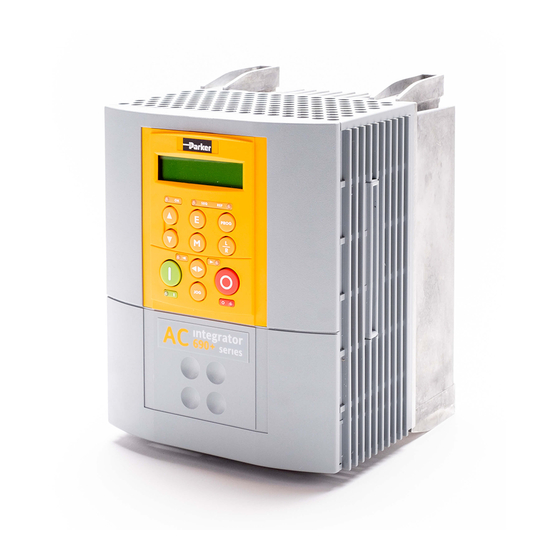
690+ Series
AC Drive
Frame B, C, D, E & F
Installation Product Manual
HA465492U005 Issue 3
Compatible with Version 5.x Software
Copyright 2004 SSD Drives Limited (formerly Eurotherm Drives Limited)
All rights strictly reserved. No part of this document may be stored in a retrieval system, or transmitted in any form or by
any means to persons not employed by an SSD Drives company without written permission from SSD Drives Ltd.
Although every effort has been taken to ensure the accuracy of this document it may be necessary, without notice, to
make amendments or correct omissions. SSD Drives cannot accept responsibility for damage, injury, or expenses
resulting therefrom.
Advertisement
Table of Contents

Related Manuals for SSD Drives 690+ Series

Summary of Contents for SSD Drives 690+ Series
- Page 1 All rights strictly reserved. No part of this document may be stored in a retrieval system, or transmitted in any form or by any means to persons not employed by an SSD Drives company without written permission from SSD Drives Ltd.
- Page 2 SSD Drives warrants the goods against defects in design, materials and workmanship for the period of 12 months from the date of delivery on the terms detailed in SSD Drives Standard Conditions of Sale IA058393C. SSD Drives reserves the right to change the content and product specification without notice. Cont.2...
- Page 3 Safety Information Requirements IMPORTANT: Please read this information BEFORE installing the equipment. Intended Users This manual is to be made available to all persons who are required to install, configure or service equipment described herein, or any other associated operation. The information given is intended to highlight safety issues, and to enable the user to obtain maximum benefit from the equipment.
- Page 4 The specifications, processes and circuitry described herein are for guidance only and may need to be adapted to the user’s specific application. SSD Drives does not guarantee the suitability of the equipment described in this Manual for individual applications. Risk Assessment Under fault conditions, power loss or other operating conditions not intended, the equipment may not operate as specified.
-
Page 5: Table Of Contents
Contents Contents Page Chapter 1 G E T T I N G T A R T E D Introduction ....................1-1 Equipment Inspection ................... 1-1 Packaging and Lifting Details ..............1-1 About this Manual ..................1-2 Initial Steps ......................1-2 How the Manual is Organised .................1-2 Information for Users without a Keypad ..........1-3 Chapter 2 A V E R V I E W O F T H E... - Page 6 Contents Contents Page Optional Equipment ................... 3-19 System Board ..................3-19 Encoder Connections ................3-20 SSD Drives Approved Encoders............3-20 Technology Options................3-21 Fitting the Remote 6901 Keypad............3-23 Top Cover ..................3-24 External Brake Resistor ................3-24 External AC Supply EMC Filter .............3-26 EMC Motor Output Filter ..............3-30 Output Contactors ................3-30...
- Page 7 Contents Contents Page Starting Methods ....................4-14 Starting Several Drives Simultaneously ..........4-15 Single Wire Logic Starting..............4-15 Two Wire Logic Starting...............4-15 Three Wire Logic Starting ..............4-15 Chapter 5 T E Y P A D Connecting the Keypad ................5-1 The Power-Up Condition ...............5-1 Controlling the Drive using the Keypad ............
- Page 8 E P A I R Routine Maintenance..................7-1 Repair ......................7-1 Saving Your Application Data ..................7-1 Returning the Unit to SSD Drives ................7-1 Disposal .........................7-1 Chapter 8 T E C H N I C A L P E C I F I C A T I O N S Understanding the Product Code ................8-1...
- Page 9 Contents Contents Page Internal Dynamic Brake Switch (Frame E)..............8-19 Internal Dynamic Brake Switch (Frame F)..............8-20 Control Terminals ....................8-21 System Board Terminals (option) ................8-22 Analog Inputs/Outputs ..................8-23 Digital Inputs ......................8-23 Digital Outputs .....................8-23 System Board Digital Inputs/Outputs (DIGIO11-15)..........8-23 Supply Harmonic Analysis (Frame B Constant) ............8-24 Supply Harmonic Analysis (Frame C Constant) ............8-25 Supply Harmonic Analysis (Frame C Quadratic)............8-26 Supply Harmonic Analysis (Frame D Constant) ............8-28...
- Page 10 Contents Contents Page Input Fuse Ratings (North America) ............9-10 European Directives and the CE Mark............9-11 CE Marking for Low Voltage Directive ..............9-11 CE Marking for EMC - Who is Responsible? ............9-11 Legal Requirements for CE Marking .............9-12 Applying for CE Marking for EMC............9-12 Which Standards Apply?..................9-12 Power Drive Product Specific..............9-12 Certificates ......................9-14...
-
Page 11: Etting
TARTED Introduction The 690+ Series AC Drive is designed for speed control of standard 3-phase induction motors. Larger models are available in a range of ratings for constant torque and quadratic torque applications. This dual mode feature provides a cost effective solution to general industrial applications, as well as the control of pumps and fans. -
Page 12: About This Manual
Chapter 5 Chapter 2 details the lists all the Operator Station parameters and menu system Chapter 8 Chapter 5 holds many of the has all the technical details macro details Installation Product Manual Software Product Manual 690+ Series AC Drive... -
Page 13: Information For Users Without A Keypad
This symbol identifies important text for users operating the drive using the default (factory) set- DEFAULT up. If the text is italic, such as this, then the information is especially for users without the keypad or suitable PC programming tool. 690+ Series AC Drive... -
Page 14: Rive
6053 technology box (optional) Earth terminals Terminal cover retaining screw Keypad port (P3) Terminal cover Future communications option (P8) Gland plate Thermistor connection Cooling fan Speed feedback board (optional) 6901 Keypad System Board (optional) Blank cover (Part Number: LA389836U001) 690+ Series AC Drive... - Page 15 RS232 programming port (P3) Comms technology box (optional) Power terminal shield Speed feedback technology box (optional) 6901 Keypad Future communications option (P8) Blank cover (Part Number: LA389836U001) System Board (optional) Control terminals Through-panel fixing plate and screws not illustrated 690+ Series AC Drive...
- Page 16 6901 Keypad Gland plate Blank cover (Part Number: LA389836U001) Gland plate retaining screw Keypad port (P3) Top cover (optional) Control terminals Future communications option (P8) Power terminals System Board (optional) Through-panel fixing plate and screws not illustrated 690+ Series AC Drive...
- Page 17 Gland plate retaining screw Blank cover (Part Number: LA389836U001) Top cover (optional) Keypad port (P3) Motor thermistor terminals Control terminals 2 2 2 System Board (optional) Power terminals Through-panel fixing plate and screws not illustrated Earthing points 690+ Series AC Drive...
- Page 18 RS232 programming port (P3) Future communications option (P8) 6901 Keypad Gland plate Blank cover (Part Number: LA389836U001) Motor thermistor terminals Keypad port (P3) System Board (optional) Control terminals 2 2 0 Auxiliary supply terminals (fan) Brake terminals 690+ Series AC Drive...
-
Page 19: Control Features
4 configurable inputs - voltage or current Outputs Analog Outputs 3 configurable outputs - voltage or current Digital Inputs 7 configurable 24V dc inputs, 1 fixed 24V dc inputs Relay Outputs 3 relay contacts (volt-free) Table 2-1 Control Features 690+ Series AC Drive... -
Page 20: Functional Overview
AC Line Choke DC Link Frames E & F Choke Frames C & D Charging Circuit CONTROL TERMINALS PROCESSOR DBR+ DBR- POWER CONTROL M1 M2 M3 Figure 2-7 Functional Block Diagram (Frames C, D, E, F) 690+ Series AC Drive... -
Page 21: Filter Board (Frame B Only)
This is a non-isolated RS232 serial link for communication with the Keypad. Alternatively, a PC running SSD Drives’ “ConfigEd Lite” Windows-based configuration software (or some other suitable PC programming tool) can be used to graphically program and configure the drive. -
Page 22: Nstalling The
If wall-mounted, the unit must be fitted with the Top Cover firmly screwed Heat Control into position. Sink Approximate Frame C shown for illustration purposes Figure 3-1 Mechanical Dimensions for 690+ Series Models Max. Weight Fixings kg/lbs Frame B 4.3/9.5 233.0 223.0... -
Page 23: Minimum Air Clearance (Frame B)
“Certification for the Drive” - Direct Wall-Mountable Models. Top Cover Control Heat Sink AIR FLOW Figure 3-3 Air Clearance for a Wall-Mount Product/Application Model Recognition Clearances for Standard Product fitted with Top Cover (mm) Frame B 690+ Series AC Drive... -
Page 24: Minimum Air Clearance (Frame C)
1.5Nm (1.2Nm recommended). Top Cover Control Heat Sink FORCED AIR FLOW Figure 3-5 Air Clearance for a Wall-Mount Product/Application Model Recognition Clearances for Standard Product fitted with Top Cover (mm) Frame C 690+ Series AC Drive... - Page 25 Fit a gasket to each side of the drive to complete the gasket seal. Ensure a complete panel seal is made; 2 extra side gaskets are provided. Offer up the drive to the panel and secure. Refer to Through-Panel Cutout Details, page 3-9. 690+ Series AC Drive...
-
Page 26: Minimum Air Clearance (Frame D)
1.5Nm (1.2Nm recommended). Top Cover ISOLATED FORCED AIR FLOWS Figure 3-8 Air Clearance for a Wall-Mount Product/Application Model Recognition Clearances for Standard Product fitted with Top Cover (mm) Frame D 15 LHS, 5 RHS 690+ Series AC Drive... - Page 27 2 extra side gaskets are provided. Offer up the drive to the panel and secure. panel Refer to Through-Panel Cutout Details, page 3-9. 690+ Series AC Drive...
-
Page 28: Minimum Air Clearance (Frame E)
1.5Nm (1.2Nm recommended). Top Cover ISOLATED FORCED AIR FLOWS Figure 3-11 Air Clearance for a Wall-Mount Product/Application Model Recognition Clearances for Standard Product fitted with Top Cover (mm) Frame E 0 (zero) 690+ Series AC Drive... - Page 29 Fit the self-adhesive gasket material to the mating face of the drive to produce an air- tight seal between the drive and the panel. Offer up the drive to the panel and secure. Refer to Through-Panel Cutout Details, page 3-9. panel 690+ Series AC Drive...
- Page 30 Installing the Drive Through-Panel Cutout Details 690+ Series AC Drive...
-
Page 31: Minimum Air Clearance (Frame F)
Fix the duct to the drive using the M4 fasteners. Fit the gasket between the duct cowling and the top of the cubicle to provide a good seal. Drill through and secure all this with the M6 fasteners. 690+ Series AC Drive... - Page 32 3-11 Installing the Drive Duct Kit Installation Diagram 690+ Series AC Drive...
-
Page 33: Electrical Installation
Frame F The gland plate holes accept the following gland sizes: 22.8mm to accept metric M20, PG16 and American ½” NPT cable gland sizes 28.6mm to accept M25, PG21 and American ¾” NPT cable gland sizes 690+ Series AC Drive... -
Page 34: Cable Gland Requirements
Screened motor connections to be made using a cable gland with a 360 degree screened connection 690+ Series AC Drive... -
Page 35: Power Wiring Connections (Frame B)
3. Feed the power supply and motor cables into the drive through the metal gland plate using the correct cable entries, and connect to the power terminals. Tighten all terminals to the correct tightening torque, refer to the Terminal Tightening Torques table. 4. Lower the internal power terminal shield. 690+ Series AC Drive... -
Page 36: Power Wiring Connections (Frame D)
Feed the power supply and motor cables into the drive through the metal gland plate using the correct Tighten all terminals to the correct tightening cable entries, and connect to the power terminals. torque, refer to the Terminal Tightening Torques table. 690+ Series AC Drive... -
Page 37: Power Wiring Connections (Frame F)
Falling temperature trip reset resistance: 750 to 1650 If the motor is not fitted with an internal thermistor, you should disable the thermistor trip function either by setting INVERT THERMIST to be TRUE, or by linking the thermistor terminals. 690+ Series AC Drive... -
Page 38: Control Wiring Connections
3-17 Installing the Drive Control Wiring Connections All 690+ Series AC Drives have the same control wiring connections. Note: Use screened control cables to comply with EMC requirements. All screens terminated using a gland at the gland plate. 1. Feed the control cables into the drive through the metal gland plate and connect to the control terminals. -
Page 39: Terminal Block Acceptance Sizes
Frame D (35 lb-in) (35 lb-in) (40 lb-in) 0.7Nm 6-8Nm 6-8Nm 6-8Nm Frame E (6.1 lb-in) (53-70 lb-in) (53-70 lb-in) (53-70 lb-in) 0.7Nm 15-20Nm 0.7Nm 42Nm Frame F (6.1 lb-in) (132-177 lb-in) (6.1 lb-in) (375 lb-in) 690+ Series AC Drive... -
Page 40: Optional Equipment
2 3 4 5 6 7 8 9 SW1 SW2 1 2 3 4 5 6 2 3 4 5 6 SW1/SW2 Switch Settings Volts set by SW1 +24V External and SW2 Power Supply positions Figure 3-17 System Board Terminals 690+ Series AC Drive... -
Page 41: Encoder Connections
To ensure compliance with the EMC Directive the overall cable screen should be connected to the encoder body and to the drive chassis. Recommended cable (pairs individually screened): Belden equivalent 8777 SSD Drives Part Number CM052666 Differential Encoders System Board Terminal B System Board Terminal D... -
Page 42: Technology Options
Frame B is a special case. Remote Operator Station Comms cable tie loop Option for restraining speed feedback board cables Frame B illustrated Top Cover Remote Operator Station Comms Speed Option Feedback Option Remote Operator Station Frame D illustrated 690+ Series AC Drive... - Page 43 Device Net 6053/DNET 6055/DNET Device Net Technology Option Manual HA463575U001 HA463575U001 TB2 Speed Feedback Technology Option Plug-in speed feedback HTTL Encoder option. LA467461 Technology Board (Frame B) 6054/HTTL Technology Box (Frames C, D, E & F) 690+ Series AC Drive...
-
Page 44: Fitting The Remote 6901 Keypad
104mm Template 48.2 96.4 possible. 10.5 Cutout Dimensions An actual size template is provided with cut-out Keypad/6052 Mounting Kit. Figure 3-18 Mounting Dimensions for the Remote-Mounted Keypad 6901 690+ Series AC Drive... -
Page 45: Top Cover
Frame D LA465058U002 Frame E External Brake Resistor Three standard power resistors are flying leads available from SSD Drives. These resistors should be mounted on a heatsink (back panel) and covered to prevent injury from burning. Part Number CZ463068 CZ388396... - Page 46 CZ353190 3.39 CZ353190 Brake Resistor Selection Note: SSD Drives can supply suitable brake resistors. Brake resistor assemblies must be rated to absorb both peak braking power during deceleration and the average power over the complete cycle. 0 0055 Peak braking power P...
-
Page 47: External Ac Supply Emc Filter
IMPORTANT: Do not use an external filter on a drive supplied with an internal ac supply EMC filter. Mount the filter as close as possible to the drive. Note: Follow the cabling requirements given in Chapter 8: “Technical Specifications” Refer to Chapter 8: “External AC Supply (RFI) Filters” for further information. 690+ Series AC Drive... - Page 48 Gland Plate : BA467840U105 Frame F 460V TN CO467841U215 95mm 825 x 250 x 795 x applicable 115mm 216mm 500V IT/TN CO467842U215 95mm 825 x 250 x 795 x applicable 115mm 216mm Gland Plate : Not applicable 690+ Series AC Drive...
- Page 49 3-28 Installing the Drive Figure 3-20 Footprint/Bookcase Mounting Filters (generic drawing) 690+ Series AC Drive...
- Page 50 3-29 Installing the Drive Figure 3-21 Gland Box for Footprint/Bookcase Mounting Filters (generic drawing) 690+ Series AC Drive...
-
Page 51: Emc Motor Output Filter
This can help the drive achieve EMC and filter thermal conformance. It also ensures longer motor life by reducing the high voltage slew rate and overvoltage stresses. Mount the filter as close to the VSD as possible. Please refer to SSD Drives for the selection of a suitable filter. Output Contactors... -
Page 52: Pre-Operation Checks
Re-apply power to the drive and system The drive has Macro 1 installed as the factory default. If you are controlling the drive in Remote control, refer to the Software Product Manual : “Application Macros” for details of other macros. 690+ Series AC Drive... -
Page 53: Control Philosophy
SPEED SETPOINT SPEED SETPOINT DEFAULT LOCAL START/STOP REMOTE START/STOP REMOTE LOCAL SPEED CONTROL SPEED CONTROL SPEED SETPOINT SPEED SETPOINT REMOTE START/STOP LOCAL START/STOP Frame B illustrated Figure 4-2 The Four Combinations of Local and Remote Control 690+ Series AC Drive... -
Page 54: Selecting Local Or Remote Control
Note: The default is for the L L /R key to be operative for both Sequencing and Reference Generation, and to be set for Remote control, i.e. both LEDs will be off. 690+ Series AC Drive... -
Page 55: Initial Start-Up Routines
(WARNING: Disconnect the mains supply first). Reading the Status LEDs The HEALTH and RUN LEDs indicate status. The LEDs are considered to operate in five different ways: SHORT FLASH EQUAL FLASH LONG FLASH HEALTH Figure 4-4 Blank Cover showing LED Operation 690+ Series AC Drive... -
Page 56: Routine 2: Local Control Using The Keypad
(WARNING: Disconnect the mains supply first). Using the Keypad (or other suitable programming tool) the drive must now be set-up: as a simple Open-loop Drive (V/F fluxing) in Sensorless Vector Fluxing mode in Closed-Loop Vector mode 690+ Series AC Drive... -
Page 57: Set-Up As An Open-Loop Drive (V/F Fluxing)
MOTOR POLES ** 4 Number of motor poles MOTOR CONNECTION ** STAR Type of motor connection AUTOTUNE ENABLE FALSE Enables the Autotune feature For more information refer to Chapter 5: “The Keypad” - The QUICK SETUP Menu. 690+ Series AC Drive... -
Page 58: Set-Up Using The Closed-Loop Vector Mode
Encoder direction Parameter is only set up if drive is configured to run as Closed- loop Vector Not measured by Stationary Autotune MAG CURRENT Magnetising current Not measured by Stationary Autotune STATOR RES Per phase stator resistance 690+ Series AC Drive... -
Page 59: Stationary Or Rotating Autotune
AUTOTUNE ENABLE parameter is reset to FALSE. In Closed-loop Vector mode (with an encoder) the encoder sign has been adjusted by the Autotune feature. IMPORTANT: Now perform a SAVE CONFIG to save your new settings. Refer to Chapter 5: “The Keypad” - SAVE CONFIG. 690+ Series AC Drive... -
Page 60: Performing A Stationary Autotune
3 minutes (for the dc link capacitors to discharge) and then swap the motor drive cables M1/U and M2/V. Change the setting of ENCODER INVERT. The encoder sign is now correct for the new motor direction. 690+ Series AC Drive... -
Page 61: The Start/Stop Mode Explained
Similarly when the JOG input (DIGITAL INPUT 5) is TRUE, the SPEED DEMAND ramps up to the JOG SETPOINT at a ramp rate set by JOG ACCEL TIME (not shown in the diagram). The drive will continue to run at the JOG SETPOINT while the JOG input remains TRUE. 690+ Series AC Drive... -
Page 62: Starting And Stopping Methods
To “stop” the remotely controlled drive remove the 24V from the RUN FWD input, terminal With the Keypad, or suitable programming tool, the drive can be selected to “Ramp to Stop”, or to “Coast to Stop” at one of two rates (STOP TIME or FAST STOP TIME). 690+ Series AC Drive... -
Page 63: Ramp To Stop
SPEED DEMAND changes immediately to 0% as soon as the Stop command is given. The power stack is also immediately disabled at this time, causing the load to coast. POWER CIRCUIT DISABLED RUN input REMOTE SETPOINT SPEED DEMAND Speed 0% Figure 4-8 Coast to Stop with a Remote Reference 690+ Series AC Drive... -
Page 64: Advanced Stopping Methods
When a trip condition is detected, a similar stopping method to NOT COAST STOP is used. The power stack cannot be re-enabled until the trip condition has been cleared and successfully reset. Refer to Chapter 6: “Trips and Fault Finding” for further details. 690+ Series AC Drive... -
Page 65: Logic Stopping
TRUE NOT COAST STOP REMOTE REVERSE REMOTE REVERSE Digital Input 4 REM TRIP RESET REM TRIP RESET Digital Input 7 TRUE TRIP RST BY RUN FALSE POWER UP START Figure 4-13 Default Sequencing Wiring (Macro 1) 690+ Series AC Drive... -
Page 66: Starting Several Drives Simultaneously
RUN REV switch causes the drive to run in reverse. Operating the NOT STOP switch (making “NOT STOP” FALSE) at any time causes the drive to stop running. Note: The JOG parameter is never latched in this way. The drive only jogs while the JOG parameter is TRUE. 690+ Series AC Drive... - Page 67 4-16 Operating the Drive 690+ Series AC Drive...
-
Page 68: Connecting The Keypad
Note: By default the drive always initialises in Remote control mode, WELCOME SCREEN with the Local control keys inactive, making it unlikely that the motor could be started accidentally. OPERATOR menu at level 1 Remote Mode (default) 690+ Series AC Drive... -
Page 69: Controlling The Drive Using The Keypad
Local Start/Stop (Seq) mode. STOP/RESET Control - Stops the motor. Only operates when the drive is in Local Sequence mode. Trip Reset - Resets any trips and clears displayed message if trip is no longer active. 690+ Series AC Drive... -
Page 70: Led Indications
FWD/REV keys. Speed Control (Ref) is controlled from the terminals Start/Stop (Seq) is controlled from the terminals ▲ Speed Control (Ref) is controlled using the up ( ) and down (▼) keys Start/Stop (Seq) and Speed Control (Ref) are controlled using the Keypad keys 690+ Series AC Drive... -
Page 71: The Menu System
VIEW LEVEL, the last parameter in the menu. Note: The contents of the OPERATOR menu remains unchanged for all view levels. Refer to “The Menu System Map”, page 5-6 to see how VIEW LEVEL changes the menu. 690+ Series AC Drive... -
Page 72: Changing A Parameter Value
E key. Experience will show how to avoid most messages. They are displayed in clear, concise language for easy interpretation. Refer to Chapter 6: “Trips and Fault Finding” for trip messages and reasons. 690+ Series AC Drive... -
Page 73: The Menu System Map
VALUE FUNC 1 VALUE FUNC VALUE FUNC 20 Note: When VIEW LEVEL is set to OPERATOR, the PROG key also toggles to the VIEW LEVEL parameter in the QUICK SETUP menu. This can be password protected. 690+ Series AC Drive... - Page 74 PRESET 1 BASIC RAISE/LOWER PRESET 8 SELECTING ADVANCED WILL SKIP FREQUENCIES DISPLAY ALL MENUS S-RAMP ZERO SPEED TRIPS I/O TRIPS STALL TRIP TRIPS HISTORY TRIPS STATUS WINDER COMPENSATION DIAMETER CALC SPEED CALC TAPER CALC TORQUE CALC 690+ Series AC Drive...
-
Page 75: The Prog Key
JOG SETPOINT is displayed as SETPOINT (JOG) Pressing the L/R key when in Remote mode takes you directly to the SETPOINT (LOCAL) parameter with the Edit mode enabled. Press the PROG key to return to the previous display. 690+ Series AC Drive... -
Page 76: The Operator Menu
Select/change a function block To select a different instance of this function block, i.e. ▲ ▼ ANALOG INPUT 2 PARAMETER PARAMETER ▲ ▼ Select/change a parameter OPERATOR MENU menu at level 4 Figure 5-4 Parameter Selection 690+ Series AC Drive... -
Page 77: String Entry
OPERATOR MENU NAME Figure 5-5 String Entry Note: For details about user-definable units, scaling factors, limits and coefficients refer to the Software Product Manual, Chapter 1: Programming Your Application - OPERATOR MENU and DISPLAY SCALE function blocks. 690+ Series AC Drive... -
Page 78: The Diagnostics Menu
The difference between the demanded speed and the actual speed. (Refer to the SPEED LOOP function block) DRIVE FREQUENCY Tag No. 591 Range: — .xx Hz Shows the drive output frequency in Hz. (Refer to the PATTERN GEN function block) 690+ Series AC Drive... - Page 79 A read-only parameter indicating the state of the brake switch. (Refer to the DYNAMIC BRAKING function block) DRIVE FREQUENCY Tag No. 591 Range: — .x Hz The drive output frequency. (Refer to the PATTERN GEN function block) 690+ Series AC Drive...
- Page 80 (VALUE) The TRUE or FALSE input, (after any inversion). (Refer to the DIGITAL INPUT function block) DIGITAL INPUT 6 Tag No. 726 Range: FALSE / TRUE (VALUE) The TRUE or FALSE input, (after any inversion). (Refer to the DIGITAL INPUT function block) 690+ Series AC Drive...
- Page 81 (VALUE) The TRUE or FALSE output demand. (Refer to the DIGITAL OUTPUT function block) DIGITAL OUTPUT 3 Tag No. 737 Range: FALSE / TRUE (VALUE) The TRUE or FALSE output demand. (Refer to the DIGITAL OUTPUT function block) 690+ Series AC Drive...
-
Page 82: The Quick Setup Menu
Input range and type DISABLE TRIPS 0000 >> Sub-menu to set disabled trips DISABLE TRIPS + 0040 >> Sub-menu to set disabled trips VIEW LEVEL TRUE Selects full menu for MMI display Table 5-1 Parameters for setting-up the drive 690+ Series AC Drive... -
Page 83: The System Menu
This menu restores the displayed application/macro to the drive. 1 SYSTEM To restore an application/macro see below. 2 RESTORE CONFIG RESTORE CONFIG RESTORE CONFIG APPLICATION ▲ ▼ RESTORE CONFIG MACRO 1 RESTORE CONFIG `UP` TO CONFIRM ▲ RESTORE CONFIG menu at level 2 690+ Series AC Drive... - Page 84 DELETE CONFIG You cannot delete the factory macros. To delete an application see below. DELETE CONFIG PUMP 1 ▲ ▼ DELETE CONFIG PUMP 2 DELETE CONFIG `UP` TO CONFIRM ▲ DELETE CONFIG menu at level 2 690+ Series AC Drive...
-
Page 85: Selecting The Language
"UP" TO CONFIRM ▲ SAVE CONFIG menu at level 2 DISPLAYS OPERATOR MENU PROG (NORMAL ACTION OF PROG KEY) SETPOINT (REMOTE) for example 0.0 % PRESS AGAIN TO RETURN TO PROG PREVIOUS MENU/PARAMETER DIAGNOSTICS menu at level 1 690+ Series AC Drive... -
Page 86: Quick Tag Information
Note: The drive must be in Configuration mode before links can be edited. Pressing the M M key at this point will display the ENABLE CONFIG page. Refer to the Software Product Manual, Chapter 1: “Programming Your Application” - Making and Breaking Links in Configuration Mode. 690+ Series AC Drive... -
Page 87: Password Protection
You can check that password protection has been removed by repeatedly pressing the E key until the Welcome screen is displayed. Pressing the E key again will NOT display the PASSWORD LOCKED screen. Note: Perform a SAVE CONFIG if you need “no password” to be saved on power-down. 690+ Series AC Drive... -
Page 88: Power-Up Key Combinations
RESTORE DEFAULTS DELETE CONFIG NEW CONFIG NAME IMPORTANT: We recommend the menus marked * * above are only used by SSD Drives or suitably qualified personnel. Refer to The SYSTEM Menu, page 5-16 for all non-highlighted menus. 690+ Series AC Drive... -
Page 89: Quick Enter Configuration Mode
You can initialise the drive in Configuration Mode by holding the STOP key during power-up. Hold down the key opposite: Power-up the drive, continue HOLD to hold for at least 2 seconds AC MOTOR DRIVE 5.5kW 400V V1.1 for example Menu System 690+ Series AC Drive... -
Page 90: Trips
Reset the trip(s) using the remote trip reset input, or by pressing the STOP key on the Keypad. DEFAULT Success is indicated by the HEALTH LED (on the unit or MMI) ceasing to flash and returning to a healthy “ON” state. The programming block SEQ & REF::SEQUENCING LOGIC::TRIPPED output is reset to FALSE. 690+ Series AC Drive... -
Page 91: Using The Keypad To Manage Trips
Internal dynamic braking switch has Trying to decelerate a large inertia load too quickly or been overloaded too often OP STATION Keypad has been disconnected from Keypad accidentally disconnected from drive drive whilst drive is running in local control 690+ Series AC Drive... - Page 92 OVERSPEED Speed feedback > 150% for 0.1 seconds UNKNOWN An unknown trip - refer to SSD Drives MAX SPEED LOW During Autotune the motor is required to run at the nameplate speed o f the motor. If MAX SPEED RPM limits the speed to less than this value, an error will be reported.
- Page 93 MOTR STALLED ERR The motor must be able to rotate during Autotune INVERSE TIME The inverse time current limit is active: motor loading is too great fixed or autoboost levels are too high Table 6-1 Trip Messages 690+ Series AC Drive...
-
Page 94: Automatic Trip Reset
If data will not save correctly, the Keytpad will display a failure message. In this case, the drive has developed a fault and must be returned to SSD Drives. Refer to Chapter 7: “Routine Maintenance and Repair". 690+ Series AC Drive... -
Page 95: Fault Finding
Motor runs and stops Motor becomes jammed Stop the drive and clear the jam Motor won’t rotate or runs in Encoder fault Check encoder connections reverse Open circuit speed Check terminal reference potentiometer Table 6-2 Fault Finding 690+ Series AC Drive... -
Page 96: Routine Maintenance
Repair There are no user-serviceable components. IMPORTANT: MAKE NO ATTEMPT TO REPAIR THE UNIT - RETURN IT TO SSD DRIVES. Saving Your Application Data In the event of a repair, application data will be saved whenever possible. However, we advise you to copy your application settings before returning the unit. - Page 97 Routine Maintenance and Repair 690+ Series AC Drive...
-
Page 98: Specifications
Standard SSD Drives livery Distributor livery 01-04,06-99 Defined customer liveries Third digit Mechanical packaging style Standard (IP20), protected panel mounting with gland plate IP20 and falling dirt protection (UL Type 1) Fourth digit Keypad No Keypad 6901 Keypad fitted 690+ Series AC Drive... - Page 99 0750 = 75kW 0900 = 90kW 0910 = 90kW (150Hp) Three numbers specifying the nominal input voltage rating: 220 to 240V ( 10%) 50/60Hz 380 to 460V ( 10%) 50/60Hz 380 to 500V ( 10%) 50/60Hz 690+ Series AC Drive...
- Page 100 Characters specifying the auxiliary mains power supply. No auxiliary supply required (Frame C – E) 110 to 120V (±10%), 50/60Hz (Frame F) 220 to 240V (±10%), 50/60Hz (Frame F) Digits specifying engineering special options: No special option 690+ Series AC Drive...
-
Page 101: Catalog Number (North America)
N Brake power switch not fitted (Frames D & E only) B Brake power switch fitted - no braking resistors supplied Note: External braking resistors should be specified and ordered separately. Characters specifying the systems board: N Not fitted S System board fitted 690+ Series AC Drive... -
Page 102: Environmental Details
The drive is only suitable for earth referenced supplies (TN) when fitted with an internal filter. (TN) and (IT) External filters are available for use on TN and IT (non-earth referenced) supplies. Prospective Short Refer to the appropriate Electircal Ratings table. Circuit Current (PSCC) Earth Leakage Current >10mA (all models) 690+ Series AC Drive... -
Page 103: Cabling Requirements For Emc Compliance
220Vac. The fan is powered from a single phase supply which uses a capacitor to generate the quadrature phase. Protect the fan using a 3A fuse. 110/120V : 130W, 10 F, Stator - 16 220/240V : 140W, 2.5 F, Stator - 62 All models All models 270cfm (459 m³/hr) 690+ Series AC Drive... -
Page 104: Electrical Ratings (230V Build Variant)
690+0007/230.. 7.5Hp 4000 690PC/0075/230/3/.. 7.5kW 6000 690+0010/230.. 10Hp 6000 Quadratic (Output Overload Motoring 110% for 60s, 130% for 0.5s short term rating) 690PC/0055/230/3/.. 7.5kW 4000 690+0007/230.. 10Hp 4000 690PC/0075/230/3/.. 11kW 49.3 6000 690+0010/230.. 15Hp 49.3 6000 690+ Series AC Drive... - Page 105 Quadratic (Output Overload Motoring 110% for 60s, 125% for 0.5s short term rating) 690PF/0300/230/3/.. 37kW 1150 1500 100000 690+0040/230.. 50Hp 1150 1500 100000 690PF/0370/230/3/.. 45kW 1350 1800 100000 690+0050/230.. 60Hp 1350 1800 100000 690PF/0450/230/3/.. 55kW 1600 2100 100000 690+0060/230.. 75Hp 1600 2100 100000 690+ Series AC Drive...
-
Page 106: Electrical Ratings (400V Build Variant)
Quadratic (Output Overload Motoring 110% for 60s) 690PC/0055/400/.. 7.5kW 18.9 1250 690+0007/460/.. 10Hp 15.6 1250 690PC/0075/400/.. 11kW 26.1 4000 690+0010/460/.. 15Hp 22.1 4000 690PC/0110/400/.. 15kW 33.6 4000 * 690+0015/460/.. 20Hp 28.5 4000 690PC/0150/400/.. 18.5kW 6000 690+0020/460/.. 25Hp 6000 690+ Series AC Drive... - Page 107 3, 6 690+0060/460/.. 60Hp 18000 Quadratic (Output Overload Motoring 110% for 60s) 690PE/0300/400/.. 37kW 15000 690+0040/460/.. 50Hp 15000 690PE/0370/400/.. 45kW 1029 18000 690+0050/460/.. 60Hp 1029 18000 690PE/0450/400/.. 55kW 1094 1242 18000 690+0060/460/.. 75Hp 1094 1242 18000 690+ Series AC Drive...
- Page 108 100,000 690+0075/460/.. 100Hp 1200 1500 100,000 690PF/0750/400/.. 90kW 1580 1950 100,000 690+0100/460/.. 125Hp 1340 1780 100,000 690PF/0900/400/.. 110kW 1800 1950 100,000 690+0125/460/.. 150Hp 1670 2180 100,000 690PF/0910/400/.. 110kW 1800 1950 100,000 690+0150/460/.. 150Hp 1670 2180 100,000 690+ Series AC Drive...
-
Page 109: Electrical Ratings (500V Build Variant)
3, 6 6000 690PD/0220/500/.. 22kW 3, 6 6000 690PD/0300/500/.. 30kW 15000 Quadratic (Output Overload Motoring 110% for 60s) 690PD/0150/500/.. 18.5kW 3, 6 4000 690PD/0180/500/.. 22kW 3, 6 6000 690PD/0220/500/.. 30kW 3, 6 6000 690PD/0300/500/.. 37kW 15000 690+ Series AC Drive... - Page 110 690PF/0550/500/.. 55kW 1130 100,000 690PF/0750/500/.. 75kW 1200 1500 100,000 690PF/0900/500/.. 90kW 1340 1780 100,000 Quadratic (Output Overload Motoring 110% for 60s) 690PF/0550/500/.. 75kW 1200 1500 100,000 690PF/0750/500/.. 90kW 1340 1780 100,000 690PF/0090/500/.. 110kW 1670 2180 100,000 690+ Series AC Drive...
-
Page 111: Input Fuse Ratings (Europe)
Frame C 690PB/0022/500/3/.. 690PC/0055/500/3/.. 690PB/0040/500/3/.. 690PC/0075/500/3/.. 690PB/0055/500/3/.. 690PC/0110/500/3/.. 690PC/0150/500/3/.. Frame D Frame E 690PD/0150/500/3/.. 690PE/0300/500/3/.. 690PD/0180/500/3/.. 690PE/0370/500/3/.. 690PD/0220/500/3/.. 690PE/0450/500/3/.. 690PD/0300/500/3/.. Frame F 690PF/0550/500/3/.. 690PF/0750/500/3/.. 690PF/0900/500/3/.. * Note : Frame B only is 50Hz 5% or 60Hz 5% 690+ Series AC Drive... -
Page 112: External Ac Supply (Rfi) Filters
Table 10 Unrestricted Distribution Radiated First Emissions Environment Above 4.0kW Table 10 Restricted Distribution Conducted Second emissions environment Table 11 Where I<=100A Conducted Second emissions environment Table 11 Where I>=100A Radiated Second Emissions environment Table 12 690+ Series AC Drive... -
Page 113: Internal Dynamic Brake Switch (Frame B)
690PC/0110/400/.. 11/15 11/15 3.4/4.5 690PC/0150/400/.. 15/20 11/15 3.4/4.5 500V Build Variant: 500V ±10%, 45-65Hz DC link brake voltage: 815V 690PC/0055/500/.. 5.5/7.5 6.1/8.2 2.25 1.8/2.5 690PC/0075/500/.. 7.5/10 12.2/16.3 3.7/4.9 690PC/0110/500/.. 11/15 12.2/16.3 3.7/4.9 690PC/0150/500/.. 15/20 12.2/16.3 3.7/4.9 690+ Series AC Drive... -
Page 114: Internal Dynamic Brake Switch (Frame D)
400V Build Variant: 380-460V ±10%, 45-65Hz DC link brake voltage: 750V 690PE/0300/400/.. 30/40 30/40 9/12 690PE/0370/400/.. 37/50 37/50 10.5/14 690PE/0450/400/.. 45/60 45/60 13.5/18 500V Build Variant: 500V ±10%, 45-65Hz DC link brake voltage: 820V 690PE/0300/500/.. 30/40 30/40 9/12 690PE/0370/500/.. 37/50 37/50 10.5/14 690PE/0450/500/.. 45/60 45/60 13.5/18 690+ Series AC Drive... -
Page 115: Internal Dynamic Brake Switch (Frame F)
690PF/0550/400/.. 55/75 62/83 18/25 690PF/0750/400/.. 75/100 90/125 24/32 690PF/0900/400/.. 90/125 102/137 24/32 690P/0910/400/.. 90/150 102/137 24/32 500V Build Variant: 500V ±10%, 45-65Hz DC link brake voltage: 820V 690PF/0550/500/.. 55/75 20.5/27 690PF/0750/500/.. 75/100 25.5/34 690PF/0900/500/.. 90/125 25.5/34 690+ Series AC Drive... -
Page 116: Control Terminals
Alternatively they may be used down to 1mA, 12V levels. This is a 6-way connector. DOUT1_A normally-open relay Default function DOUT1 closed = healthy contacts DOUT1_B DOUT2_A normally-open relay Default function DOUT2 closed = running contacts DOUT2_B DOUT3_A normally-open relay No default function contacts DOUT3_B 690+ Series AC Drive... -
Page 117: System Board Terminals (Option)
Output (repeats Slave Encoder) Repeat Encoder Output B Output (repeats Slave Encoder) Repeat Encoder Output /B Output (repeats Slave Encoder) Repeat Encoder Output Z Output (repeats Slave Encoder) Repeat Encoder Output /Z Output (repeats Slave Encoder) 690+ Series AC Drive... -
Page 118: Analog Inputs/Outputs
+ 0.6V 15-24V dc = ON 0V dc = OFF (-30V dc absolute * range: 19.1V (full load) to 25.1V (no load) minimum, +30V dc threshold absolute maximum) EXT 24Vin - 0.6V Input Impedance 6.8k Sample Rate 690+ Series AC Drive... -
Page 119: Supply Harmonic Analysis (Frame B Constant)
11.0 11.4 10.5 10.0 Total RMS 16.2 22.4 11.2 19.2 12.4 16.2 17.5 10.0 13.5 Current (A) THD (V) % 0.37 0.64 0.80 0.46 0.67 0.83 1.22 0.19 0.33 0.37 0.58 0.68 0.73 0.31 0.48 0.62 690+ Series AC Drive... -
Page 120: Supply Harmonic Analysis (Frame C Constant)
13.9 14.4 15.9 13.3 10.8 15.6 10.7 11.0 12.8 Total RMS 24.5 33.2 14.5 18.9 26.2 36.5 14.2 25.5 26.5 29.2 Current (A) THD (V) % 0.57 0.86 0.40 0.54 0.70 1.03 0.40 0.70 0.72 0.87 690+ Series AC Drive... -
Page 121: Supply Harmonic Analysis (Frame C Quadratic)
23.9 10.8 12.7 17.5 19.4 10.4 10.6 13.5 18.4 13.0 15.3 Total RMS 30.6 18.6 25.7 34.4 43.9 19.9 23.4 32.2 35.6 Current (A) THD (V) % 0.68 0.4848 0.6858 0.8634 1.1883 0.5286 0.6545 0.8396 1.0236 690+ Series AC Drive... -
Page 122: Supply Harmonic Analysis (Frame D Constant)
21.8 11.3 13.0 14.7 Total RMS 44.9 52.8 65.0 34.8 40.5 47.2 65.8 27.5 33.2 39.1 Current (A) THD (V) % 0.90 0.93 1.05 0.85 0.96 1.08 1.44 0.74 0.85 0.96 * Please contact SSD Drives. 690+ Series AC Drive... -
Page 123: Supply Harmonic Analysis (Frame D Quadratic)
16.4 19.6 25.5 13.0 14.7 17.8 Total RMS 54.0 65.0 40.5 47.2 60.8 83.8 32.6 39.1 50.5 Current (A) THD (V) % 0.97 1.05 0.96 1.08 1.30 1.72 0.85 0.96 1.16 * Please contact SSD Drives. 690+ Series AC Drive... -
Page 124: Supply Harmonic Analysis (Frame E Constant)
64.4 42.4 35.3 42.2 48.4 29.3 36.7 43.1 22.2 22.9 27.2 29.4 20.2 24.8 27.6 Total RMS 90.7 67.5 80.8 94.7 54.8 69.1 82.6 Current (A) THD (V) % 1.65 2.58 3.70 3.41 1.31 1.61 1.82 690+ Series AC Drive... -
Page 125: Supply Harmonic Analysis (Frame E Quadratic)
75.5 49.1 41.9 48.7 55.2 35.4 43.1 48.9 21.7 26.0 30.3 32.2 23.3 28.0 30.1 Total RMS 115.6 81.3 94.6 110.0 67.1 82.2 95.2 Current (A) THD (V) % 1.84 2.98 3.46 3.84 1.52 1.84 1.02 690+ Series AC Drive... -
Page 126: Supply Harmonic Analysis (Frame F Constant)
19.5 19.5 19.1 19.0 22.1 22.5 22.2 10.0 10.3 Total RMS 102.3 126.2 148.2 110.9 144.3 164.3 168.9 93.3 118.4 140.2 Current (A) THD (V) % 1.33 1.52 1.66 1.71 1.98 2.12 2.15 1.67 1.90 2.06 690+ Series AC Drive... -
Page 127: Supply Harmonic Analysis (Frame F Quadratic)
18.6 19.0 21.9 22.2 21.7 10.1 11.5 10.3 10.5 Total RMS 125.9 148.2 183.9 143.8 163.8 196.8 168.9 118.0 140.2 166.0 Current (A) THD (V) % 1.49 1.66 1.87 1.95 2.13 2.34 2.15 1.87 2.06 2.25 690+ Series AC Drive... -
Page 128: Requirements For Emc Compliance
For compliance with EMC requirements, we recommend that the “0V/signal ground” is separately earthed. When a number of units are used in a system, these terminals should be connected together at a single, local earthing point. 690+ Series AC Drive... -
Page 129: Cabling Requirements
Causing RCDs (Residual Current Devices) to trip due to increased high frequency earth current. Producing increased heating inside the EMC ac supply filter from the increased conducted emissions. These effects can be overcome by adding chokes or output filters at the output of the VSD. 690+ Series AC Drive... -
Page 130: Emc Installation Options
Do not use cubicle constructions that use insulating mounting panels or undefined mounting structures. Cables between the VSD and motor must be screened or armoured and terminated at the VSD or locally on the back panel. 690+ Series AC Drive... -
Page 131: Star Point Earthing
Used for signal/control screened cables which do not go directly to the VSD. Place this busbar as close as possible to the point of cable entry. ‘U’ clamp the screened cables to the busbars to ensure an optimum HF connection. 690+ Series AC Drive... -
Page 132: Sensitive Equipment
Video cameras and closed circuit TV Office personal computers Capacitive devices such as proximity sensors and level transducers Mains borne communication systems Equipment not suitable for operation in the intended EMC environment, i.e. with insufficient immunity to new EMC standards 690+ Series AC Drive... -
Page 133: Requirements For Ul Compliance
For correct field wiring connections that are to be made to each terminal refer to Chapter 3: “Installing the Drive” - Power Wiring Connections, and Control Wiring Connections. Terminal Tightening Torques Refer to Chapter 3: "Installing the Drive" - Terminal Tightening Torques. 690+ Series AC Drive... -
Page 134: Recommended Wire Sizes
Model Catalog Code Power Input Power Output Brake Output for North America 230V Build Variant: 220-240V ±10% CONSTANT 690+/0007/230/.. 690+/0010/230/.. QUADRATIC 690+/0007/230/.. 690+/0015/230/.. 400V Build Variant: 460V ±10% CONSTANT 690+/0007/460/.. 690+/0010/460/.. 690+/0015/460/.. 690+/0020/460/.. QUADRATIC 690+/0007/460/.. 690+/0010/460/.. 690+/0015/460/.. 690+/0020/460/.. 690+ Series AC Drive... - Page 135 Terminal acceptance range: 6-1/0 AWG Model Catalog Code Power Input Power Output Brake Output for North America 230V Build Variant: 220-240V ±10% CONSTANT 690+/0030/230/.. QUADRATIC 690+/0030/230/.. 400V Build Variant: 460V ±10% CONSTANT 690+/0040/460/.. 690+/0050/460/.. 690+/0060/460/.. QUADRATIC 690+/0040/460/.. 690+/0050/460/.. 690+/0060/460/.. 690+ Series AC Drive...
-
Page 136: Field Grounding Terminals
Therefore, the installer must provide correct Type 1 closures for all unused clearance holes provided within the drive’s glandplate. Type 1 Enclosed models are suitable for use in no worse than a Pollution Degree 2 environment. 690+ Series AC Drive... -
Page 137: Input Fuse Ratings (North America)
690+/0010/460/.. 690+0003/460/.. 690+/0015/460/.. 690+0005/460/.. 690+/0020/460/.. 690+0007/460/.. 690+0010/460/.. Frame D Frame E 690+/0020/460/.. 690+/0040/460/.. 690+/0025/460/.. 690+/0050/460/.. 690+/0030/460/.. 690+/0060/460/.. 690+/0040/460/.. Frame F 690+/0075/460/.. 690+/0100/460/.. 690+/0125/460/.. 690+/0150/460/.. * Note : Frame B only is 50Hz 5% or 60Hz 5% 690+ Series AC Drive... -
Page 138: Synchronous Motor Control
FLUXING menu at level 3). Using Line Chokes Line chokes are not required to limit input current to SSD Drives Inverters. Controllers from 5.5kW ( 400v) or 2.2kW ( 230v) upwards are fitted with DC link chokes to limit the ripple current seen by the DC link capacitors and thus prolong their life. -
Page 139: Using Output Contactors
50 H CO055193 CO055253 50 H CO055253 50 H 50 H 243A CO057960 50 H 360A CO387886 360A CO387886 50 H 360A CO387886 50 H Table 10-1 Recommended Choke Values for Cables up to 300 Metres 690+ Series AC Drive... -
Page 140: Using Multiple Motors On A Single Drive
Dynamic braking increases the braking capability of the drive by dissipating the excess energy in a high power resistor connected across the dc link, see above. Refer to the Power Wiring Connection Diagrams in Chapter 3. 690+ Series AC Drive... -
Page 141: High Starting Torque
It is therefore most important for good winder performance that the diameter is reset to the correct value before the machine is started. The following diagrams show typical ways to preset the roll diameter. 690+ Series AC Drive... - Page 142 The reel speed reference however, needs to be driven from the Line Reference in order to give good acceleration performance for the winder. The following diagram shows the Line Reference and Line Speed signals used to give an improved accuracy winder. 690+ Series AC Drive...
-
Page 143: Basic Set-Up Instruction
The following information is required from the winding machine manufacturer in order to set up the winder blocks: Absolute minimum roll diameter. Absolute maximum roll diameter. Absolute maximum line speed. Motor maximum speed, at smallest roll diameter and maximum line speed. 690+ Series AC Drive... -
Page 144: Set-Up With No Web Connected To The Winder
Simple Centre Winder Equations It is assumed that the winders operate in constant tension mode. Unwind Line Reference Rewind Tension Tension Belt / Gearbox Belt / Gearbox Speed Speed Torque Torque Motor Motor Figure 10-6 Constant Tension Winder 690+ Series AC Drive... - Page 145 Power Power Power Power Roll Inertia Friction Referring motor with field weakening Diameter Build Power Power Power Power Motor Inertia Friction Cons Power Range Here, Constant Power Range motor field weakening range. This parameter field weakening 690+ Series AC Drive...
- Page 146 Gearbox Motor Speed The maximum motor speed will exist under the following conditions: Maximum line speed Smallest core diameter Maximum gearbox ratio Speed Line Speed 19 1 . Roll Diameter Speed Speed Ratio Motor Roll Gearbox 690+ Series AC Drive...
-
Page 147: 4-Q Regen Control/Common Dc Bus Applications
Product Code (Europe), indicating that Special Option 7 is applied (“Y” cap disconnection). MMI Menu Map The 690+ Series AC Drive product range provides a control mode designed to simplify common DC bus applications. 1 SYSTEM Macro 8 is provided to simplify the set-up of 4-Q Regen systems by automatically configuring 2 RESTORE CONFIG the drive. -
Page 148: Multi-Motor System
The 4-Q Regen drive draws sinusoidal, unity power factor current from the supply and only has to be rated for the net power consumed by the system or by the system braking requirements. Dynamic Braking (eg. for Emergency Stopping purposes) can still be used in this control mode if required. 690+ Series AC Drive... -
Page 149: Brake Mode
We recommend that standard SSD Dynamic Braking resistors are used for the external pre- charge circuit. The continuous and peak power capabilities of these resistors are given below: SSD Part N Continuous Power Peak Power Rating Resistance ( ) Rating (W) (kW) CZ389853 CZ463068 CZ388396 12.5 690+ Series AC Drive... - Page 150 Simply sum the DC Link capacitance for all the drives on the common DC Link and select the appropriate pre-charge network. For example a system comprising 5, 30kW, 400V Frame E drives would have a total DC Link capacitance of: 2500 Total 690+ Series AC Drive...
-
Page 151: 3-Phase Choke Sizing
014 T5 RLX-0320- RLX-0320- 011 T5 010 T5 RLX-0500- RLX-0500- 0.135 011 T5 010 T5 RLX-0600- RLX-0600- 0.105 011 T5 010 T5 "T5" indicates the choke is fitted with a normally-closed thermal switch that opens at 185°C. 690+ Series AC Drive... -
Page 152: Software Function Block
Software Product Manual. The control mode must be set to 4-Q REGEN and the leakage inductance set to the value Note: of total line choke inductance. Refer to page 10-10. Macro 8 provides the following connections: 690+ Series AC Drive... -
Page 153: Connection Diagram
AC supply voltage. These should be fast semiconductor protection fuses. Each individual drive connected to the common DC Bus must be protected by DC Link fuses in both the DC+ and DC- lines. The fuses must be of suitable current rating and capable of 690+ Series AC Drive... -
Page 154: Emc Filtering
EMC Filtering We recommend all 690+ Regen systems meet the EMC product specific standard EN61800- 3:1997 . To achieve this, an EMC filter is required. Contact SSD Drives for details of suitable filters. All drives in a common DC link scheme using a 4-Q Regen front-end must have their Note: internal "Y"... - Page 155 SP = Supply Power (kW) V = Supply Line Volts (V) Fit DC link fusing to protect cabling to each drive. IMPORTANT: Check the voltage rating of any DC link components. Voltages >700V are common. 690+ Series AC Drive...
-
Page 156: The Default Application
Software Product Manual - Chapter 1: Programming Your Application. The OPERATOR Menu for Macro 0 The default OPERATOR menu is shown below. STARTUP SCREEN SETPOINT (REMOTE) SPEED DEMAND DRIVE FREQUENCY MOTOR CURRENT LOAD DC LINK VOLTS CURRENT LIMITING ENTER PASSWORD 690+ Series AC Drive... -
Page 157: Macro 1: Basic Speed Control (Default)
0..+10 V – [719] TYPE – FALSE – [711] BREAK ENABLE – FALSE – [718] BREAK ENABLE – 0.00 % – [716] BREAK VALUE – 0.00 % – [723] BREAK VALUE – Macro 1: Basic Speed Control (default) 690+ Series Frequency Inverter... - Page 158 DIGITAL OUTPUT 2 Running 0V = stopped, 24V = running The Operator Menu for Macro 1 The default Operator Menu is shown below. OPERATOR MENU SPEED DEMAND DRIVE FREQUENCY MOTOR CURRENT TORQUE FEEDBACK DC LINK VOLTS 690+ Series Frequency Inverter...
Need help?
Do you have a question about the 690+ Series and is the answer not in the manual?
Questions and answers