Table of Contents
Advertisement
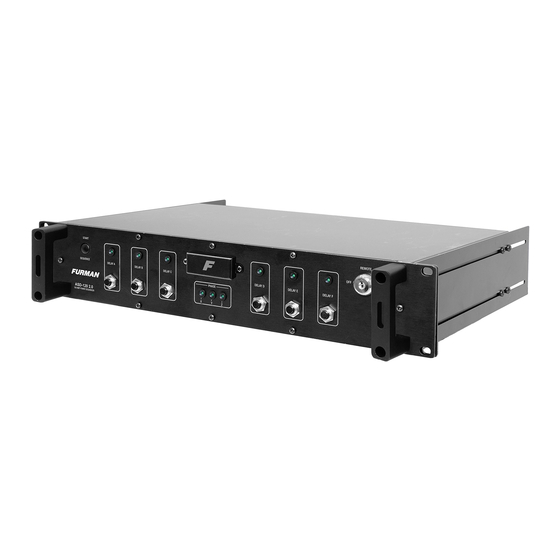
ASD-120 2.0
OWNER'S MANUAL
SIX CHANNEL SEQUENCING POWER DISTRIBUTION
WARNING! ELECTRIC SHOCK HAZARD. CONNECTION OF A POWER
DELAY A
DELAY B
INPUT CABLE TO THIS DEVICE AND TO A POWER SOURCE MUST BE
DONE BY QUALIFIED PERSONNEL ONLY.
DANGER: MANIPULER SEL ON LES INSTRUCTIONS DU
FABRICANT ET CONFIER LA MAINTENANCE A UN T
ECHNICIEN QUALIFIE
INPUT 120 / 3Ø, 208 / 240 VAC
14400 WATTS – 120 AMPS MAX
20A MAX
20A MAX
DELAY F
DELAY C
DELAY D
DELAY E
20A MAX
20A MAX
20A MAX
20A MAX
FORCE OFF
REMOTE
12V STAT REM GND
DELAY OUTPUTS
NC A B C D E F NO
DRY RELAY CONTACTS - RATING 48V / 1 AMP
10007825 REV. B ASD-120 2.0 INST.
10-15
Advertisement
Table of Contents

Related Manuals for Furman ASD-120 2.0


Summary of Contents for Furman ASD-120 2.0
- Page 1 DRY RELAY CONTACTS - RATING 48V / 1 AMP INPUT 120 / 3Ø, 208 / 240 VAC 14400 WATTS – 120 AMPS MAX 20A MAX 20A MAX 20A MAX 20A MAX 20A MAX 20A MAX 10007825 REV. B ASD-120 2.0 INST. 10-15...
-
Page 2: Introduction, Before You Begin, And Important Safety Note
20A MAX IMPORTANT SAFETY NOTE: While the subject of attaching a power cable to the ASD-120 2.0 is covered in the Wiring Instructions, the connection to utility power or generator power is not. We strongly recommended that the ASD-120 2.0 be installed by a qualified... -
Page 3: Table Of Contents
ASD-120 2.0, please use the Direct Current 12V and REM terminals of the • Input power must be connected by a qualified electrician. The unit must be ASD-120 2.0 to provide the DC control signal to the REM input of the older ASD- properly grounded through a protective earth ground connection. -
Page 4: Wiring Instructions
X, Y, and Z bus bars in support of a balanced 120/208V 4AWG for a 120/240 single phase source. three phase input. If a 120/240 source is connected to the ASD-120 2.0, the Z bus bar is not used and the load conductors connected to this bus bar must be Cable efficiency losses per foot are listed in Table 1. -
Page 5: Rear Rack Mounting Ears
Internal power distribution block terminals (See torque specs on page 3). 1. Remove the screws from the side of the ASD-120 2.0 adjustable rear rack ear. 2. Reverse the rack ears and reattach the rack ears to the chassis (as shown here). -
Page 6: Product Features
SEQUENCE DELAY A DELAY B DELAY C DELAY D DELAY E DELAY F PHASE ASD-120 2.0 120 AMP POWER SEQUENCER Circuit Breakers 20A Delay Indicator LEDs for Circuit Breakers 20A Front Panel Key Switch Integrated Front Panel for Delay A, B and C... -
Page 7: Product Overview
ASD-120 2.0 units. Furman products provide a practical means of centralized control over an extensive network of The ASD-120 2.0 can be thought of as an array of six high current relays that op- power distribution and conditioning equipment. - Page 8 Delay Bank. If a Delay Bank breaker has been tripped, the Delay Bank LED indicator may still illuminate green even though power is not being The ASD-120 2.0 features a set of three phase indicators; X, Y, and Z that will delivered to the Delay Bank with an open breaker.
- Page 9 ASD-120 2.0 will sequence all Delay Banks on and remain on. When SET TO MIDDLE the key is in the OFF position, the ASD-120 2.0 will sequence all Delay Banks OFF POSITION and remain off. When the key is in the REMOTE position the ASD-120 2.0 will...
-
Page 10: Front Panel Configurations And Features
FORCE OFF Settings MIDDLE POSITION DIP Switch position 4 is used to define how the ASD-120 2.0 will implement its FORCE OFF feature. FORCE OFF is a safety feature that is designed to cut AC The Multi-Function DIP Switch ALWAYS OFF power to all outlets instantaneously. - Page 11 Sequences the ASD-120 2.0 ON when REM is connected to GND terminal GND ON Sequences the ASD-120 2.0 OFF when REM = Open Circuit Momentary Momentary Sequences the ASD-120 2.0 from ON to OFF or OFF to ON each time +12V is applied to the REM input. Momentary Momentary...
-
Page 12: Asd-120 2.0 Programming Summary
The factory default setting for 12VDC ON is “OFF” or disabled. If 12VDC ON is set and the Start Sequence button. to ON, the ASD-120 2.0 will sequence ON if 12VDC is applied to the remote pin on the remote interface. -
Page 13: Rear Panel Control Terminal Interface
REMOTE INTERFACE PIN 4 GND (Power) The ASD-120 2.0 has a remote interface which can be used to control the ASD- The GND (ground) terminal operate in unison with Delay A through F. GND can 120 2.0 remotely using a Furman RS-1 (Maintained) or RS-2 (Momentary) wall also be fed back into the REM pin (Pin #3) to activate the sequence when the switches. -
Page 14: Advanced Installation Topics
A sequence is initiated by turning the key switch past the REMOTE position to initiate a sequence Note: The ASD-120 2.0 sequences each Delay Bank in order from A to F when ON or OFF. sequencing ON, and turn Banks F to A OFF in the reverse order when sequenc-... - Page 15 4. SEQUENCE ON using external 5 to 30VDC power supply. In this mode, an will activate the ASD-120 2.0 when DIP 4 is in (N.C.) mode. This DIP setting is reserved for alarm systems. Factory default for DIP 4 is (N.O) mode position UP.
- Page 16 ON position and returned to the REMOTE position, the ASD-120 2.0 When the Key Switch is in the REMOTE position, the ASD-120 2.0 will respond as defaults to ON in either Maintained Mode or Momentary Mode.
-
Page 17: Local Operating Modes
+12V output for as long as the button is depressed. Any If someone does press the button, the ASD-120 2.0, if ON, will start an OFF connected Furman products with REM and GND terminals will also cycle on or off. - Page 18 DIP 4 (N.O.) mode is recommended. Only a short across the Forced Off terminals will activate the ASD-120 2.0 if DIP 4 is in the (N.C.) mode. This DIP setting is reserved for alarm systems. Factory default for DIP 4 is (N.O) mode position UP.
-
Page 19: Product Installation Examples
5 6 7 All RS-2 Remote System Control Panel or Momentary locations will activate the ASD-120 2.0 program sequence. The Primary RS-2 Remote System Control Panel has priority over the other control panels. When the key switch of the Primary RS-2 is set to the “DISABLED” position the operation of the other RS-2 Control Panel locations will be defeated. - Page 20 1. Configure ASD-120 2.0 Multi-Function DIP Set for Normally Closed & Maintained M-8S REMOTE PORT Mode ON. • DIP 1, 2 & 3 DOWN - ASD-120 2.0 Delay Time cannot exceed M-8S Delay Time. • DIP 4 UP – (NO), verify factory default. PS-REL •...
- Page 21 Caution: The OFF sequence for the CN2400S and ASD-120 2.0 units will start at the same time. In order to avoid timing conflicts while ramping down, the CN-2400S should be set to a longer delay time interval than all the time intervals on each ASD-120 2.0 sequencer.
-
Page 22: Specifications
SPECIFICATIONS AC Input Voltage Control/Status/Triggering (Rear Panel) 120/240V single phase, or 120/208V three phase. Remote Terminal: Phoenix 4 Pin Connector with Screw Terminals; Input Current: 120 amps maximum +12V @ 250mA, STAT, REM, GND (Class 2 wiring) Output: Six, 120V 20A circuits +5 to 30VDC at REM terminal. -
Page 23: Warranty Information
Authorization) number. To receive an RMA number, please contact Furman Technical Services at techsupport@furmansound.com or call, (800) 472-5555, Furman, a brand of Core Brands LLC., warrants its ASD-120 2.0 (the “Product”) between the hours of 6 a.m. and 4 p.m., U.S. Pacific Time. In order to issue an... - Page 24 +5V to 30VDC at REM. Furman • 1800 S. McDowell Blvd. • Petaluma, CA. 94954 800-472-5555 • www.furmansound.com © 2015 Core Brands. All rights reserved. Furman is a registered trademark of Core Brands, a Nortek, Inc. Company 10007825 REV. B ASD-120 2.0 INST. 10-15...
Need help?
Do you have a question about the ASD-120 2.0 and is the answer not in the manual?
Questions and answers