Table of Contents
Advertisement
Advertisement
Table of Contents

Related Manuals for FLORA pp2512uv


Summary of Contents for FLORA pp2512uv
- Page 1 PP2512UV User's Guide ADD: Guanlan Hi‐tech Industry Park, Huanguan South Road, Baoan District, Shenzhen, China P.C:518110 TEL:+86‐755‐27521666 FAX+86‐755‐27521866 Victor Xu Page 1 12 Jan. 2011 Copyright 2011 © Shenzhen Runtianzhi Image Technology, Co., Ltd.
-
Page 2: Table Of Contents
Table of Contents ............................ 5 LORA IGITAL RINTING YSTEM .................................. 5 ISCLAIMER ........................ 5 ANUAL SAGE ONDITIONS AND IMITATIONS ................................ 5 ONTENTS OF ACKAGE ............................... 6 RINTER NTRODUCTION ............................. 6 ABLE ENERAL EATURES ............................ 6 ABLE ... - Page 3 LORA 5.1 Pre‐Installation Requirement ......................... 38 5.2 Machine Pre‐Installation .......................... 38 5.3 Installation of software .......................... 38 5.3.1 Installation Procedure of PhotoPRINT Server Flora Edition 6.1v2 ................38 5.3.2 Installation procedure of flora driver ........................41 Victor Xu Page 3 12 Jan. 2011 Copyright 2011 © Shenzhen Runtianzhi Image Technology, Co., Ltd.
- Page 4 5.3.3 Add setup ................................42 5.4 Install print heads ............................ 42 5.5 Ink and Solvent Preparation ........................... 45 5.6 Test print ................................ 45 5.5.1 Test print tool bar ..............................45 5.5.2 Set parameter ................................45 5.5.3 Print head alignment .............................. 4 7 5.5.3.1 Mechanical Alignment (Y‐Align) .......................... ...
-
Page 5: Flora Digital Printing System
Disclaimer This is an alpha release of the User's Guide for Flora PP 2512UV printer. We have made every effort to guarantee the accuracy and integrity of the information in this manual. If you find some errors or omissions, please bring them to our attention so we can check and correct them accordingly. -
Page 6: Printer Introduction
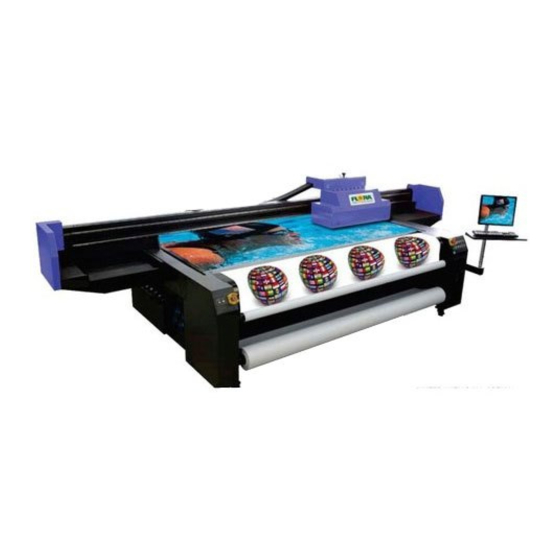
Printer Introduction The Flora PP 2512UV printer is a wide format digital printer suitable for small up to medium size business use. It uses a UV curable ink, which is environment friendly. It provides high productivity and is capable to replace traditional silkscreen printing. -
Page 7: About The Manual
2512 Ink Type About the manual The manual provides the end user all the information related to the machine basic functions, software installation, machine parameter calibration, maintenance and troubleshooting of Flora PP 2512UV. Victor Xu Page 7 12 Jan. 2011 Copyright 2011 ©... -
Page 8: Chapter 1 - Safety Operating Instructions
Chapter 1 - Safety Operating Instructions Brief Introduction This chapter introduces the important safety information. Please read and understand the safety information carefully before operating the printer. Safety Information FLORA printer uses the following chemical substances • All kinds of printing media • UV Ink •... -
Page 9: Ink And Solvent Spillage, A Potential Risk Of Fire And Explosion
1.2.5 Ink and solvent spillage, a potential risk of Fire and explosion • Store ink and solvent in proper cabinet for flammable liquid storage. • Keep ink and solvent containers tightly closed at all times. If a container has sign of damage/leakage, fix or replace it immediately. •... -
Page 10: Printer
one electrical outlet. 1.5.2 Printer 1. Do not place anything on top of the printer. 2. Do not rest you elbows on the printer. 3. Open and close the top cover gently from the front of the printer with both hands. 4. -
Page 11: Chapter 2 - Pre-Install
Chapter 2 - Pre-install Getting Started This section provides the necessary information to operate the printer. Familiarize yourself with the basic of the printer before reading Section 2. Contents of this section: − Operating conditions − Consumables − External Views, Part Names and Functions Operating Conditions This section describes the operating conditions for the printer. -
Page 12: Available Media Types
2.3.1 Available Media Types The following types of media are available: Paper Advertising banner Mesh Fabrics Adhesive Vinyl Glass Sheets Ceramics Steel Sheets Acrylic Boards KT Boards PVC Boards Foam Boards Note: Contact our service center for detail Victor Xu Page 12 12 Jan. -
Page 13: Chapter External Views Part Names And Functions
Chapter 3 - External Views, Part Names and Functions Carriage Assembly Beam Assembly Flat Bed Monitor & Key board Assembly Load ink Area Left Control Panel Right Control Panel Maintenance Station Print Head Carriage Assembly The print head carriage assembly houses the print heads, secondary ink tanks, print head control board, raster reader, negative &... -
Page 14: Auto Detect Media Thickness Sensor
Two Rows Platform Three Rows Platform 3.1.2 Auto Detect Media Thickness Sensor This mechanism will perform media thickness check every time you send an image for printing. This part will detect the top surface of the media Carriage Assembly Media Height Detector Assembly 3.1.3 UV Lamp Assembly UV lamp assembly is a device for curing UV ink. -
Page 15: Pressure Sensor
control panel and software. AC power Cable Heat dissipation Fans Left UV Lamp Right UV Lamp 3.1.4 Pressure Sensor The negative pressure display setting parameters are programmed to control the maximum positive pressure thereby protecting the print head from excessive pressure. There are two pressure sensors in total for every printer: one controlling negative pressure, while the other one controlling positive. -
Page 16: Rail Guide And Beam Assembly
Rail guide and Beam Assembly Rail guide supports pathway for carriage and Beam moving, and the beam serves as frame for rail guide mounting. 3.3.1 X-axis Rail guide and Beam Dual Liner Lead Rail Bearing slider Enlarge View Carriage Assembly Beam Assembly 3.3.2 Y-axis Rail guide Left lead screw... -
Page 17: Control Panel
Control Panel 3.4.1 Maintenance Control Panel The maintenance control panel is placed at left shoulder. The ink prime button is use to purge ink out of the print head nozzles, which will help purge the print head. The negative pressure regulator can be used to adjust negative pressure. The E-stop button will shut off main power supply to this machine when emergency situation, which will protect the print head from damaged. -
Page 18: Main Circuit Breaker
Forward Button: Pressing this button will make the beam towards the operator. Backward Button: Pressing this button will make the beam away from the operator. UV Buttons: The UV Buttons will turn on/off the UV lamps. UV1 Buttons controls the left UV lamp while the UV2 controls the right UV lamp. -
Page 19: Electrical Fixation Shelf
Electrical fixation Shelf The electrical control panel contains the servo motor drivers for the Beam Movement servo motors, Carriage servo motor and Media Feeding and Take-Up System servo motor, DC Power supplies, Servo card, USB_IF control board and the Main Circuit breaker. Servo Driver for Carriage Power Supply 1... -
Page 20: Uv Power Supply & Vacuum Pump
UV Power Supply & Vacuum Pump The UV power supply provides power to UV lamps and the intensity of light can be adjusted to Low or High. While the Media suction pumps provide suction on the flat bed to hold the media in place while printing is on progress. -
Page 21: Chapter 4 - Working System Of Flora Pp 2512Uv
Chapter 4 - Working System of Flora PP 2512UV Brief Introduction The Flora PP 2512UV large format printer is using raster image technology to process photos stored in computer. It is one of the most innovative products, which combines photo digital technology with high precision engine driver. -
Page 22: Pcb Boards
Drop Volume/Size 14 pL Drop Speed 6 ± 0.5 m/s Printing Width 36.03 mm Heater Temperature Under 55 ºC Drive Board Head Chip Manifold Left Side Right Side Heater Nozzle Plate Thermistor Ink Jet Parts of the Konica Minolta PCB boards 4.3.1 Print Head Connector Board This board is used a s interface board for Print h ead and the Print head Control Board thru a 30-pin flexible data cable. - Page 23 Print Head Connector Board 4.3.2 Print head Control Board The image data is fetched by the Print Head Control Board from the USB_IF buffer through the Image Data Cable (UCBJ10PHBJP1) and 100-pin JP1 AMP connector. The image is then processed by the image data processor and dispatch to the print heads. The printheads fires the ink depending on the binary status read by the Raster Reader which is sent to the print head control board.
- Page 24 Interfaces for print heads: Carriage platform with two rows print heads: PORT COLOR PORT JB10 JB11 JB12 JB13 JB14 JB15 JB16 COLOR **Double white just replaceV1, V2 with W3, W4 Carriage platform with three rows print heads: PORT COLOR PORT JB10 JB11 JB12...
- Page 25 to drive the servo system mechanism. PHB JP1 5V input SCB J5 X-axis Y-axis Green Led: power indicator Led: connection indicator Communication indicator: D1: NULL D2: NULL D3: NULL D4: NULL D5: Print head board indicator Communication: on D6: Y-axis indicator Y motor moving: on D7: Servo Card indicator Communication: on...
- Page 26 Number 1 means that there is no ink in the secondary tank: If there is a sound of buzzer, choose “flood” in the GUI of flora driver; Else check the indicator LED on the Printing Control Board, if the negative pressure tank level indicator LED is on, you need to go to 3) and solve the over flow problem first.
-
Page 27: Moving System
ink ,then load ink; Second, check the ink pump: make sure the pump is not damaged, if it is bad, change it; Third, check the sensor: make sure the sensor can detect the level exactly, otherwise change it; If everything can’t work still, change Servo Card. Number 2 means some ink over flowed, which also means there is ink in the negative pressure tank: Check the ink indicator LED is light or not, it means there is ink in the negative... -
Page 28: Servo Motor
4.4.1.2 Servo motor Servomotors (SM) are controlled by their respective Servo Drivers (SD). They are responsible in driving carriage X-axis, Y-axis and Z-axis movements. SD4 controls the SM4 which is responsible in driving the carriage X-axis movement. It is installed at the right end of the beam. Servo motor Machine Back View 4.4.1.3 Raster reader and strip... -
Page 29: Anti-Crash Sensor
4.4.1.5 Anti-crash Sensor The safety anti-crash sensor designed on both sides of carriage can detect the media circumstance beforehand and protect the print heads from a crush hazard. While the anti- crash sensor detects that the edge of media is cocked, the machine will initiate an emergency stop to prevent print heads from damage. -
Page 30: Z-Axis (Auto Height Adjusting System)
Left home position switch & back limited switch Right home position switch&back limited switch 4.4.3 Z-axis (Auto height adjusting system) In order for the printer to print seamlessly on different kinds of media, the carriage height should adjust automatically to whatever media thickness it should print upon. For this specific printer model it is equipped with a carriage that could automatically adjust its height depending on the media thickness to be printed upon. -
Page 31: Raster Reader And Strip
Photographic Side View of Height Adjustment Module +24Vdc Pulse +5Vdc Cable connections Illustration for Carriage Height Adjustment Module 4.4.3.2 Raster reader and strip The Raster Encoder and Raster Strip are installed inside the back plate of carriage besides the worm gear for moving the carriage up and down. 200DPI Raster Strip 200DPI Raster... -
Page 32: Ink Supply& Negative Pressure System
lower limit switch and the upper limit switch control the carriage highest and lowest allowable height the carriage can move respectively. Carriage minimum height limit switch Switch actuators Carriage maximum height limit switch Right Side of the Carriage Enlarged View Ink supply&... -
Page 33: White Ink Circulation System
4.5.2 White ink circulation system White ink is different from other color ink, because it is easy to sediment. Circulation system is specially designed for this property of white ink. The system can make white ink circulate in the ink line, which will also protect head nozzles from clogging. 4.5.3 Ink alarm system Ink alarm system plays a part in caution when the ink bottle is empty or the secondary tank is not full. -
Page 34: Overflow Protection System
4.5.5 Overflow protection system Ink protection tank serves as the ink overflow protection for the vacuum line system. If overflow happens, the ink will flow into this tank, once the ink reaches the maximum level, the sensor will shut off the print head control board. Without the ink protect tank, the vacuum system will fail to function if the tubes are filled with overflowed ink. -
Page 35: Individual Purge System
4.5.7 Individual purge system Individual purge system allows for easy convenient respective maintenance of print head, which will help saving ink also. Swap switch Positive position Negative position Vacuum system 4.6.1 Variable Vacuum Control System The variable vacuum control system allows users to change the vacuum area to match the media width to achieve the best vacuum efficiency and keep the edge of substrate from cocking. -
Page 36: Intelligent Curing Mode
4.7.2 Intelligent curing mode Intelligent curing mode is supply with software. Customer can choose different curing modes for special quality. It depends on the software to set the shutter opening and closing to achieve the function. For more detail, please refer to 6.4.6.5 4.7.3 Two level power The power was divided into two levels, which is selectable for different media by customer. -
Page 37: Automatic Registration Pin System
Automatic Registration Pin System Automatic registration pin system aid easily edge to edge printing, which simplifies the media location and ensure the high effective printing output. Registration Pins Victor Xu Page 37 12 Jan. 2011 Copyright 2011 © Shenzhen Runtianzhi Image Technology, Co., Ltd. http://www.floradigital.com... -
Page 38: Chapter 5 - Installation Manual Of Flora Pp 2512Uv
Chapter 5 – Installation manual of Flora PP 2512UV Pre-Installation Requirement The minimum working area should be 610 cm x 585 cm, this includes the space for the operator to move around the machine conveniently and safely. Prepare the necessary AC plug on the power cord attached to the machine. Please see the Technical Specification table for the power requirements. - Page 39 4) The Application Installer Setup will now prepare the Install Shield for the setup process, then click “Next”. You will get a window for 【License Agreement】, please choose “I accept the terms of the license agreement” 5) Click “Next” ,then 【Select Features】 and the 【Select Program Folder】 screen window will show up.
- Page 40 7) The 【Product Selection】 window will comes in after that. Please enter password which you can find from the dongle. And then choose “PhotoPRINT SERVER Flora Edition 6.1v2” from product Enter your password Select your language Select your product 8) Tick the “Install to desktop” selection on 【Install Manager】 window. Then click “OK”.
-
Page 41: Installation Procedure Of Flora Driver
5.3.2 Installation procedure of flora driver 1) Insert the FloraPrint Driver. From the list of Folder under Print Driver, select corresponding machine model (eg: PP2512VKM) folder. Then double-click the setup file; 2) Files will be extracted and later on 【Welcome】 window will appear. Click “Next”, coming with 【choose setup language】... -
Page 42: Add Setup
5.3.3 Add setup 1) Find the PhotoPrint 6.1 on the desktop and double click to open; 2) If it is the first time your install, it will prompt you to add your setup, or you can click “Add Setup…” from “Setup” menu; 3) Then select the brand name of the printer and the model name. - Page 43 Open the anti-static plastic bag and remove the head. Remove the head cap. The serial number should match Note: The head is pre-loaded with ink analog to prevent drying of the nozzles during transportation. The head is also equipped with a cap to protect the nozzle surface and prevent drying of the ink analog.
- Page 44 Install the print head one by one by removing printhead fixation screws from the carriage printhead mounting plate first, position the printhead and replace the two fixation screws accordingly. The back fixation screw must be slightly tightened to allow the printhead to move with minimum vertical shake, while the front fixation screw must be tightened properly before doing Y-align.
-
Page 45: Ink And Solvent Preparation
Connector Female Flat Data Guide connector Cable Print head Control Board Connector Flat Data Cable Slot Male connector Proper Connection of Flat Data Cable Print head Check all the connection again to ensure there are no misconnections and loose connections on the data cables. - Page 46 Sometimes getting the best dot print quality is a painful process so it needs patience. All you can do is play with temperature and voltage settings. The recommended Voltage setting range is controlled by Flora driver software so there’s no chance you set the voltage beyond the recommended range. While the recommended temperature setting is 40-45ºC in most cases ink manufacturers have...
-
Page 47: Print Head Alignment
Yellow, White and Varnish print heads must print the same result. 5.5.3.1 Mechanical Alignment (Y-Align) On Flora driver GUI, click Test Print button and on the Test Printer tab select Y- align then click “Test print” button. The result should look as shown below. - Page 48 Noticed there are sets of horizontal lines for K1 and K2. For the purpose of identifying sets of horizontal lines, K1 horizontal lines are colored pink, and the K2 is black though in actual print they are all printed black. The first sets of horizontal lines is a K1 single broken line and K2 solid line, ignore the first 4 sets, select the rightmost set (with more horizontal lines) to get more accurate alignment.
-
Page 49: Internal Alignment
↑ Go up Illustration for M&Y Printheads Y Align Need ↓ down Illustration for C&M printheads Y Align Good aligned Illustration for W print heads Y Align Please take note W3 and W4 print heads Y-align are using different color just for the sake of making the illustration easier to understand. - Page 50 On the Photoprint Job Properties click Driver Option >click advance button> offset button > tick the Internal of head and add the -1 mathematically on the Left table for C1 box as shown below. You can also navigate thru Test Printer Tab by clicking the settings icon as shown in the lower left of Illustration.
-
Page 51: Right Align
Default value for M1 is 0+2=2 Tick Internal of head Follow the same steps when doing Internal of head alignment for other print heads not shown in the Illustration above. 5.5.3.3 Right Align There are 16 print heads in 8 colors in total. As they are fixed in different physical position, it is necessary to do Right Alignment for secondary colors, or the secondary color will be fuzzy and the output picture will be rough. -
Page 52: Print Head X Align
Default value of C1 is 1361 1361+5=1366 1366 Tick Between of heads 5.5.3.4 Print head X Align X alignment is very necessary for Bi-direction print mode. If this alignment is not good, the output image will be rough and fuzzy because of dislocation output coming from double directions. -
Page 53: Step Align
Default value of C1 is -1810 -1813 -1810-3=-1813 Tick Between of heads 5.5.3.5 Step Align On the printer tab select Step Align option then click send print as shown below. Further below shows how the print out should look like. The Illustration shows three different scenarios. - Page 54 Figure 2 shows the motor step value when the test was sent is lower than exact value so we need to decrease, by trial and error method you can get the correct value. Fig. 3 – Correct Media Feeding Step Figure 3 shows the motor step has exact value so no need for any changes.
-
Page 55: Chapter 6 -Operation Manual Of Flora Pp 2512Uv
Chapter 6 -Operation manual of Flora PP 2512UV Brief Introduction This chapter introduces the details of operating the operating instructions of the machine from starting up to shutdown procedure. Starting-up Activities It is highly recommended to do housekeeping before starting to operate the machine. Maintaining good housekeeping helps improve the quality of the output as well as the safety of operator. -
Page 56: Editing The Image
Job queue shows the list of all jobs that have been printed, aborted, ripped and new added jobs waiting to be sent for editing or ripping. Add job icon Printer model Printing job queue Ripping job queue Ripping job queue 6.4.2 Editing the Image Figure below shows the image layout parameters like: printing size, margins, number of copies and orientation of image. -
Page 57: Work Flow Tag
6.4.3 Work Flow Tag Figure below shows the option what to do with the job file after printing. There are three options available for the end users: Delete – the image will be lost after printing is completed Hold – the image will be retained in the job folder after printing is completed Archive –... -
Page 58: Test Print Tag
1,Color correction Box 2,ICC check box 3,Media check box 4,Resolution option box 5,Color mode box 6,Dither type box 6.4.5 Test Print Tag This test is being performed in order to verify the conditions of the Print head nozzles before printing. It prints a swatch which could represent the nozzles to be firing on a definite order. From the FloraPrint driver window, select “Test Print head”... - Page 59 -Flat X-base: define the mechanical position start to print on X-axis -Flat Y-base: define the mechanical position start to print on Y-axis Media’s position & Margin: -margin: keep the margin on the media -Media to X-base: set the counter-position to print -Page header: keep header space on the media Media:...
- Page 60 -Measure Height of media check box: Tick this box, the software will measure height at every time before print a job. -Not Inquery if Measure Height check box: Un-tick this box, it will pop out the dialog box as below: -Center mirror image &...
- Page 61 -Repeat: repeat printing double, triple, quadruple times. More repeat times makes darker image output. Please refer to PhotoPrint Flora Edition Software. White Mode: -Double White check box: The mode can only be used under uni-direction mode. It will print white ink when the carriage comes from left to right.
-
Page 62: Shut-Off Procedure
Left UV Lamp: -Left bulb: when it lighted up, that means the left UV bulb will turn on when it moving to left. -Right bulb: when it lighted up, that means the left UV bulb will turn on when it moving to right. - Page 63 Close the left case cover. Switch-off the ventilation and lighting in the printing room if necessary. Perform Housekeeping if necessary. Victor Xu Page 63 12 Jan. 2011 Copyright 2011 © Shenzhen Runtianzhi Image Technology, Co., Ltd. http://www.floradigital.com...
-
Page 64: Chapter 7 Service And Maintenance Manual Of Flora Pp 2512Uv
Chapter 7 Service and Maintenance manual of Flora PP 2512UV Brief Introduction This is to describe the various service and maintenance procedure to be observed in using this PP 2512UV machine. Maintenance of print heads 7.2.1 Flushing a Selected Print head Disconnect the connection of the Ink Tube Inlet from the Ink Supply Line, insert the tubing of the Syringe with the compatible solvent inside. -
Page 65: Changing Defective Air Pump
sensor will energize the LED on the Print head Control Board when the secondary ink tank is full. If the LED doesn’t light after 2 minutes of pumping, then most likely the pump is defective or there’s a leak somewhere along the input line. Please take note of the polarity of the power supply cable for the ink pump, usually the red wire is connected to positive “+”... -
Page 66: Maintenance Of Y-Axis
duty grease on contact surfaces. Raster strip should be clean with IPA moisten clean cloth. Both should be done weekly. Raster Strip Guide Slider Slider Rails Carriage bearing bearing Timing Belt Guide Rail Guide Rail Carriage Right Slider bearing Guide Rail and Raster Strip Carriage Left Slider bearing Timing belts should be check monthly for traces of damages, misalignment and loose tension. -
Page 67: Maintenance Of Z-Axis
7.4.3 Maintenance of Z-axis Media Height Auto Adjustment System should be clean and lubricate applicable parts weekly. Worm Gear Assembly Media Height Sensor 200DPI Raster Strip 200DPI Media Height Raster Sensor Reader Media Height Sensor Assembly Media Height Adjustment System 7.4.4 Maintenance of auto-clean system Print head Wiping System should be clean and lubricate applicable part weekly. -
Page 68: Chapter 8 - Appendices
Chapter 8 - Appendices Appendix A Material Safety Data Sheet for UV Inks SECTION 1: Chemical Product And Company Identification PRODUCT NAME: VUV-Yellow/Magenta/Cyan /Black/LightMagenta/LightCyan PART NO: VUV-Y /VUV-M/VUV-C/VUV-K/VUV-LM/VUV-LC SUPPLIER: SHINY COLOR INKS INC. AGENT: XUKE Advertising Equipment Inc. Shenzhen, Guangdong China TEL NO: 0086-755-84150772 FAX NO:... - Page 69 SECTION 7 Handling and Storing USAGE PRECAUTIONS: Keep container sealed. Provide good ventilation. Avoid spilling, skin and eye contact. Avoid inhalation of vapors. STORAGE PRECAUTIONS • Keep in cool, dry, ventilated storage and sealed containers. • Protect from light, including direct sunrays. •...
- Page 70 Relative density (g/cm3,25): not determined Solubility in water (g/l,20): not soluble SECTION 10: Stability and Reactivit y Stability: Stable under normal conditions in tightly closed container decomposition if used according to specifications. Materials to Avoid: Avoid contact with oxidizing materials, strong acids, strong bases, air or oxygen. Hazardous Polymerization: Not relevant.
- Page 71 S-26 In case of contact with eyes, rinse immediately with plenty of water and seek medical advice. S-28 After contact with skin, wash immediately with plenty of water. S-36/37/38 Wear suitable protective cloth and gloves and eye/face protection S-60 This material and its container must be disposed of as hazardous waste. SECTION 16 Other Information This data sheet is prepared in accordance with directive.
-
Page 72: Appendix B Preventive Maintenance Checklist
Appendix B Preventive Maintenance Checklist Item Daily Weekly Monthly Quarterly Semi-annual Annual Ink Supply Level Check and shake on startup Waste Ink Bottle Check for level, dispose if full or nearly full Ink Filters Change Ink Pumps Check and replace if necessary UV Lamps Check and... -
Page 73: Appendix C Troubleshooting Guide
Appendix C Troubleshooting Guide Problems Probable Causes Solution No ink flowing to the tube line of the Print head Carriage 1. Fill-up empty ink barrel Empty ink supply in the Ink 2. Replace clogged ink line tubing and ink barrel filter Clogged Ink line tubing and One particular... - Page 74 No Print at all No presence of The Optical Cable must have Interchanged again the Rx/Tx connection Printhead been interchanged during of the Optical Cable either from the PCI Voltage from installation card or in the Printhead Control Board RTZ software Adjust the Printer Carriage between 2.0 –...
- Page 75 Feeding of the Pinch Roller Adjust the tension of the Pinch Roller (see is not equal Pinch Roller Inconsistent step Worn-out Gear Box Adjustment Procedure) align problem Assembly Replace worn-out Reducer Gear Box Defective Motor Encoder Replace Y-Axis Servo Motor Worn-out Timing Belt Replace Timing Belt Raster Strip might have...
-
Page 76: Appendix D Glossary
Appendix D Glossary Adobe Acrobat - Software package created by Adobe for converting any document to an Adobe Portable Document Format (PDF) file. Anyone can open your document across a broad range of hardware and software using the downloadable, free software Adobe Acrobat Reader, and it will look exactly as you intended—with layout, fonts, links, and images intact. - Page 77 Dot Size - Relative size of halftone dots as compared to dots of the screen ruling being used. There is no unit of measurement to express dot size. Dots are too large, too small or correct only in comparison to what the viewer finds attractive.
- Page 78 Hypertext Markup Language (HTML) - A series of formatting commands that describes the components of graphics and text material presented on the World Wide Web in a consistent manner Image Area - Portion of paper on which ink can appear. Image - Usually a photograph that is “translated into a bitmapped”...
- Page 79 Raster Image Processor (RIP) - A combination of computer software and hardware that controls the printing process by calculating the bit maps of images and instructs the printing device to create the images. Most RIPs operate on PostScript. Resolution - The DPI or dots per inch of a design. Measured by how many dots or pixels are in one inch of a design.
Need help?
Do you have a question about the pp2512uv and is the answer not in the manual?
Questions and answers