
Related Manuals for Smartec IPSC1

Summary of Contents for Smartec IPSC1
- Page 1 User Manual LED Strobe Controller Family IPSC1 IPSC2 IPSC4 HPSC1 HPSC4 Version 2.1.1 www.SMARTEKvision.com © SMARTEK d.o.o. 2017, information is subject to change without prior notice, Version 2.1.1 from 2017-04-28...
- Page 2 For customers in Canada This apparatus complies with the Class A limits for radio noise emissions set out in the Radio Interference Regulations. Pour utilisateurs au Canada Cet appareil est conforme aux normes classe A pour bruits radioélectriques, spécifiées dans le Règlement sur le brouillage radioélectrique.
- Page 3 Trademarks All trademarks, trade names and products represented in this document, unless stated otherwise, are brands protected internationally by law. No use of these may be made without prior, written authorization of SMARTEK d.o.o except to identify the products or services of the company. Warranty SMARTEK d.o.o.
-
Page 4: Table Of Contents
2.4. Mechanical Drawings ....................11 2.4.1. Dimensions of HPSC1 ..................11 2.4.2. Dimensions of HPSC4 ..................12 IPSC-Series ....................... 13 3.1. IPSC1 ........................13 3.1.1. Dimensions ...................... 14 3.2. IPSC2 ........................15 3.2.1. Dimensions ...................... 16 3.3. IPSC4 ........................17 3.3.1. - Page 5 5.2.1. Ethernet Status ....................27 5.3. Error / Fault Codes ....................28 Getting Started ......................29 6.1. System Requirements ..................... 29 6.2. Software Installation – SMARTEK Vision ScLib ............30 6.3. Getting Started with the Strobe Controller ............... 30 Device Configuration with the ScLibClient ..............33 7.1.
-
Page 6: Overview
1. Overview 1.1. Description Strobe controllers are used for strobing LED illuminations in machine vision applications. Very high power pulses are aligned to external trigger with high accuracy. Precise current overdrive and very small camera image exposition are used for acquisition of high-speed motion objects. User adjustable output voltage provides high efficiency and low power consumption. -
Page 7: Cabling Recommendation
For longer cable lengths, it is further recommended to raise the voltage of the illumination. This can be realized by using series LED arrays requiring higher voltage together with a device of our IPSC series, providing up to 200V on output. 1.4. Family models IPSC1 IPSC2 IPSC4-r2 HPSC1... -
Page 8: Hpsc-Series
2. HPSC-Series 2.1. Mechanical and Electrical Specifications Specification HPSC1 HPSC4 Output channels Asynchronous Operation Full timing independent channels Continuous, External Trigger, Internal Trigger, Operating Modes Software Trigger, External Switch Max. Voltage 48V (pulsed/continuous) Max. current pulse 40A @ 48V (per channel) 40A @ 48V (depends on pulse width) 160A @ 48V (in total) -
Page 9: Value Ranges And Precision
2.2. Value Ranges and Precision To raise the current precision at lower levels, the current control is split into three ranges. The following chapters describe the precision of different attributes over the set output current per channel. 2.2.1. Accuracy over Current Range Based on the applied current level, the resolution is adjusted as shown in Table 2. -
Page 10: Physical Interfaces
2.3. Physical Interfaces Configuration Ethernet (shown) USB2.0 RS-232 Trigger Output Trigger Input Open-collector, max. 30V / 50mA, Opto-isolated Opto-isolated (HPSC4) Power Input External power supply, LED Power Ouput 12 - 24V, max. 150W Power output for illumination Figure 1: Physical Interfaces shown for example on HPSC1 2.3.1. -
Page 11: Trigger Inputs
2.3.2. Trigger Inputs To physically trigger the strobe controllers by an external synchronization source, each device provides a count of input trigger lines (TRG), by a connector described in Table 5. Pin# HPSC1 HPSC4 Phoenix Contact Phoenix Contact MSTB 2,5/ 2-ST-5,08 MSTB 2,5/ 8-ST-5,08 Connector TRG1 TRG2 TRG3 TRG4... - Page 12 Figure 2: Internal input trigger scheme for HPSC-Series SMARTEK Vision | User Manual – LED Strobe Controller Family | Doc. v2.1.1...
-
Page 13: Led Output
2.3.3. LED Output The LED connectors, as shown in Figure 1 and described in Table 7, provide the power output (LED) for the illumination to be driven by the controller. Pin# HPSC1 HPSC4 Phoenix Contact Phoenix Contact MSTB 2,5/ 2-ST-5,08 MSTB 2,5/ 8-ST-5,08 Connector LED1... -
Page 14: Trigger Output
2.3.4. Trigger Output Every controller provides a generic trigger output (OUT) for synchronization of other devices. The connector assignment is described in Table 8. Pin# HPSC1 HPSC4 Phoenix Contact Phoenix Contact MSTB 2,5/ 2-ST-5,08 MSTB 2,5/ 8-ST-5,08 Connector OUT1 OUT2 OUT3 OUT4 Type OUT+ Trigger Output n +... - Page 15 Figure 4: HPSC4 – Trigger Output (OUT) – Schematics SMARTEK Vision | User Manual – LED Strobe Controller Family | Doc. v2.1.1...
-
Page 16: Mechanical Drawings
2.4. Mechanical Drawings 2.4.1. Dimensions of HPSC1 74,60 4,20 16,50 Figure 5: Dimensions of HPSC1 in mm SMARTEK Vision | User Manual – LED Strobe Controller Family | Doc. v2.1.1... -
Page 17: Dimensions Of Hpsc4
2.4.2. Dimensions of HPSC4 6,40 Figure 6: Dimensions of HPSC4 in mm SMARTEK Vision | User Manual – LED Strobe Controller Family | Doc. v2.1.1... -
Page 18: Ipsc-Series
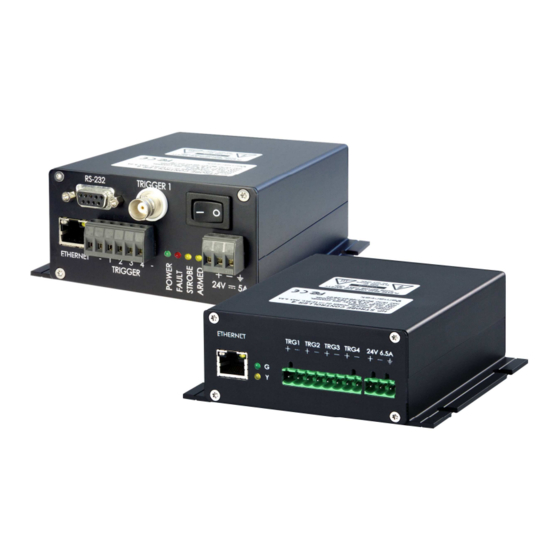
3. IPSC-Series 3.1. IPSC1 Figure 7: IPSC1 – Front panel view Specification IPSC1 Output channels Continuous, External Trigger, Internal Trigger, Operating Modes Software Trigger, External Switch 200V (pulsed) Max. Voltage 55V (continuous) Max. current pulse 20A @ 200V (depending on pulse width) Max. -
Page 19: Dimensions
3.1.1. Dimensions Figure 8: Dimensions of IPSC1 in mm and [inch] SMARTEK Vision | User Manual – LED Strobe Controller Family | Doc. v2.1.1... -
Page 20: Ipsc2
3.2. IPSC2 Figure 9: IPSC2 – Front panel view Specification IPSC2 Output channels Asynchronous Operation No timing independent channels Continuous, External Trigger, Internal Trigger, Operating Modes Software Trigger, External Switch 200V (pulsed) Max. Voltage 55V (continuous) Max. current pulse (depending on 10A @ 200V per channel (20A total) pulse width) Max. -
Page 21: Dimensions
3.2.1. Dimensions Figure 10: Dimensions of IPSC2 in mm and [inch] SMARTEK Vision | User Manual – LED Strobe Controller Family | Doc. v2.1.1... -
Page 22: Ipsc4
3.3. IPSC4 Figure 11: IPSC4 – Front panel view Specification IPSC4 Output channels Asynchronous Operation No timing independent channels Continuous, External Trigger, Internal Trigger, Operating Modes Software Trigger, External Switch 200V (pulsed) Max. Voltage 55V (continuous) Max. current pulse 10A @ 200V per channel (40A total) (depending on pulse width) Max. -
Page 23: Dimensions
3.3.1. Dimensions Figure 12: Dimensions of IPSC4 in mm and [inch] SMARTEK Vision | User Manual – LED Strobe Controller Family | Doc. v2.1.1... -
Page 24: Physical Interfaces
3.4. Physical Interfaces 3.4.1. Power Input The input power connector is located near the lower right corner of the IPSC front panel. All devices require an external 12V – 24V DC supply for operation, specified in Chapter 3. Description Phoenix Contact MSTB 2,5/ 3-ST-5,08 Type Power Supply (+12 to 24V DC) -
Page 25: Output Connector
3.4.2. Output Connector Figure 13: IPSC1/2/4 – Rear panel view with output connector Pin# IPSC1 IPSC2 IPSC4 Deltron DT13W3 1 2 3 4 5 Type 6 7 8 9 10 CH1-, Channel 1 - CH1-, Channel 1 - CH1-, Channel 1 -... - Page 26 Figure 15: IPSC-Series - Trigger Output – Schematics SMARTEK Vision | User Manual – LED Strobe Controller Family | Doc. v2.1.1...
-
Page 27: Trigger Input
3.4.3. Trigger Input Pin# IPSC1 IPSC2 IPSC4 Phoenix Contact Phoenix Contact Phoenix Contact MSTB 2,5/ 6-ST-5,08 BNC-Connector MSTB 2,5/ 2-ST-5,08 MSTB 2,5/ 4-ST-5,08 TRIGGER TRIGGER 1 TRIGGER Type + or 1 Trigger Channel 1 + Trigger Channel 1 + Trigger Input 1 +... - Page 28 3.4.3.1. Opto-Isolated Trigger Source Figure 17 shows how an opto-isolated digital output of e.g. a camera can be connected to trigger an IPSC. The opto-coupler of the trigger source should be able to supply at minimum 20mA current and be rated for minimum 24V voltage. The shown pull down 1.2kΩ...
-
Page 29: Interfaces For Configuration
4. Interfaces for Configuration 4.1. Ethernet The strobe controller can be connected directly to the PC’s network interface card or via a switch by using an Ethernet patch cable. Standard protocols used are HTTP, UDP and TCP. Pin # Signal Table 17: Ethernet connector PIN assignment IPSCx / HPSC1 HPSC4... -
Page 30: Universal Serial Bus (Usb)
4.3. Universal Serial Bus (USB) Strobe controllers providing a USB interface can be connected by an USB1.x/2.0 cable providing Type-A to -B connectors. Pin no. Signal Table 20: USB-B connector assignment The USB connection is detected by the operating system as an USB-to-Serial converter and provides a serial COM-port. -
Page 31: Status Leds
5. Status LEDs The HPSC and IPSC series have a different concept of Status LEDs. The following chapter describes the LEDs and signaling, as well as the error codes stated by those LEDs. 5.1. HPSC-Series All Strobe Controllers of the HPSC-series provide a green and a yellow status LED on the front panel of the device. -
Page 32: Ipsc-Series
5.2. IPSC-Series On the devices of the IPSC-series, there are 4 status LEDs on the front panel: Identifier Color Type IPSC1 IPSC2 IPSC4 POWER Green POWER FAULT FAULT Yellow1 STROBE STROBE ARMED Yellow2 ARMED Table 23: IPSC - Identification of status LEDs on different models When powering the device, POWER (green) and STROBE (yellow) LEDs are constantly ON, and the FAULT (red) LED is flashing for 5 seconds. -
Page 33: Error / Fault Codes
5.3. Error / Fault Codes If the device detects an error it switches to idle mode and stops driving current on output immediately. There are 9 different error codes stating the source of the error: Error # Description No error Error in internal bus communication No light head is detected by AID (IPSC-series only) Wrong parameters are used... -
Page 34: Getting Started
6.1. System Requirements (1) SMARTEK Vision Strobe Controller of IPSC- or HPSC-Series (2) Power Supply with flying leads and ferrules o IPSC1 / 2: 12V to 24V DC with at least 84W o IPSC4 / HPSCx: 12V to 24V DC with at least 135W / 150W... -
Page 35: Software Installation - Smartek Vision Sclib
(5) LED illumination o Note: The illumination must not be equipped with any additional internal / external control electronics! (6) Trigger source (optional) o 0 – 24V (voltage level for logical “1” from 3V). o IPSC-Series: 1.2kΩ / 0.5W resistor per trigger channel (optional for Hi/Hi-Z trigger sources) (7) PC with Microsoft Windows®... - Page 36 Step 3 – Establishing a connection: In the list of strobe controller, choose the device you want to connect to and press the button Connect Device. Alternatively, Ethernet strobe controller can be reached with their web-interface by typing the configured IP address into the address field of your web browser (e.g.
- Page 37 Apply and store the settings by pressing the button Send & Save which applies and stores the settings to the strobe controller. Further information on the configuration interface can be found in the following Chapter 7 - Device Configuration with the ScLibClient. SMARTEK Vision | User Manual –...
-
Page 38: Device Configuration With The Sclibclient
7. Device Configuration with the ScLibClient The ScLibClient is a graphical user interface application for strobe controller discovery, configuration and status. It is part of the ScLib which is a collection of software tools, programming samples and documentation to configure, run and integrate devices into user applications. -
Page 39: Find Devices
7.1. Find Devices Run the ScLibClient and click Find icon to start searching for devices. Figure 21: ScLibClient – Discovery Button 7.2. Discovery by Broadcast The usual way to identify available devices on Ethernet, RS-232 or USB is to search for them using a broadcast. -
Page 40: Ethernet Specific Discovery Options
Figure 23: ScLibClient – Connect to Device 7.3. Ethernet Specific Discovery Options When using an Ethernet connection, the user can choose between Broadcast and search by IP. Broadcast is the default option and the fastest way to discover devices within the home network. - Page 41 Figure 25: ScLibClient – Device List If no controller is found, make sure every connection is plugged properly and the network interface card is enabled. Further the firewall-settings might block packets from the strobe controller and can be deactivated temporary for further investigation. Invalid IP Address / Set IP Address The strobe controller can have for various reasons an IP address that does not fit to the current network configuration, which is thus invalid for establishing a connection.
- Page 42 Figure 27: ScLibClient – Set IP Window Note: When the Strobe Controller is in a different network as the PC, it can be discovered using Search by IP and connected only if the gateway is correctly set. Gateway and DNS are currently only implemented on HPSC4 devices.
-
Page 43: Strobe Controller Status
7.4. Strobe Controller Status When a connection between ScLibClient and controller is established, all fields are read out in controller status. Controller status is defined in the lower left corner of the ScLibClient software: • Controller Model – shows the model of the strobe controller. •... -
Page 44: Running Modes
7.6. Running Modes All Strobe Controllers can be operated in different Running Modes, supporting pulsed and continuous DC current output. Figure 29: ScLibClient – Running Modes In pulse controlled output modes, a Strobe Controller generates electrical impulses on the output. The output pulses in this mode can be triggered by an external-, internal or software generated trigger source. -
Page 45: Off
7.6.1. The controller is in idle mode and does not respond to any input triggers. There is no voltage drawn on any output line. 7.6.2. External Trigger In the External Trigger mode the device is ready to accept external trigger signals and generates a very precise output pulse according to the user configuration. -
Page 46: Output Parameters
7.7. Output Parameters Using the output parameters, current and voltage can be configured individually for each channel. These parameters should only be applied carefully meeting the specifications of the connected LED illumination. Too high output parameters can lead to permanent damage of the illumination. -
Page 47: Optimal Autosense
• Optimal Autosense – Enables / Disables Optimal Autosense for the internal power supply • Output Voltage – Voltage of the internal power supply, set by Optimal Autosense • Measured Voltage – Measured voltage at the internal power supply 7.7.1. Optimal Autosense Optimal Autosense is used to determine the optimal output voltage for the current set-up. -
Page 48: Controller Settings
7.7.2. Controller Settings The controller settings allow the user to modify general values of the strobe controller’s internal sensing. Figure 31: ScLibClient – Controller Settings This feature is only supported by HPSC4 devices and comprises: • Max. Input Power – Limits the maximum recharging rate, used to limit the load on the external power supply while recharging internal capacitors. -
Page 49: Trigger Input
7.8. Trigger Input 7.8.1. Trigger Input Parameters With the trigger parameters, the timing options of the Trigger- (OUT) and LED-outputs (LED) are configured. Figure 32: ScLibClient – Trigger Parameters All parameters have a resolution of 1µs: • Trigger Edge – configuration of controller's input trigger edge. If the trigger edge is not the same between camera and strobe controller, asynchronization may occur between them. - Page 50 The Trigger Input(s) parameters are not used if the controller is in Continuous, External Switch or Off mode. The HPSC4 series provides different trigger Delay/On times for LED and OUT used for manual synchronization of camera and light source. Figure 33 below shows how the timing of each trigger input line is transferred to the corresponding output(s).
-
Page 51: Lightheads (Ipsc-Series Only)
7.9. Lightheads (IPSC-series only) To access the light heads options click on the Light heads tab. Figure 34: ScLibClient - Configure Light head By using the Auto Detect button additional information is provided about the currently connected light heads. Only the light heads with digital light head signature can provide additional information. - Page 52 Figure 36: ScLibClient - Light head Information Controller – these parameters are changed when changing IP address of the strobe controller. These parameters are also read out in the controller status field: • Connection – IP address of the strobe controller •...
- Page 53 Single Circuit Definition defines parameter for single circuit: • Circuit Description – defines the name of circuit. • User Data – circuit user data. • LED Serial Count – number of LEDs connected in series. • LED Parallel Count – number of LEDs connected in parallel. •...
- Page 54 7.9.1.3. ID Check Mode and Analog ID IPSC1, IPSC2 and IPSC4 with firmware version 1.2 and up provide optional features. ID Check Mode is used to preform checking of Digital ID and Analog ID. To change setting for ID Check Mode, please contact our sales partner or Smartek support.
- Page 55 • 5 – IPSC checks for DID and AID at startup • 6 and 7 – IPSC checks for DID at startup and AID continuously all the time Analog ID is optional feature to check if light head is connected to IPSC. Pins 7 and 8 on IPSC output are connected with 1K resistor.
-
Page 56: Firmware Update
7.10. Firmware Update Firmware updates are applied to a device by flashing a binary firmware file, using the configuration interface (Ethernet, RS-232 or USB) of the Strobe Controller. The device has to be in OFF mode, updates via Ethernet must be applied having a permanent IP address (not DHCP) set. - Page 57 6) After re-programming has successfully finished, “PASSED” is indicated in text window. Depending on the device, this process can take a couple of minutes. When updating of new firmware finishes, simply close the dialog box. SMARTEK Vision | User Manual – LED Strobe Controller Family | Doc. v2.1.1...
-
Page 58: Other Features
7.11. Other features The following section shows further features of the ScLibClient configuration software. 7.11.1. Description Tab Open the Description tab to see major features, specifications and maximum ratings of the controller that is connected to theScLibClient. 7.11.2. Log Tab To see actual logging information, open the Log tab. -
Page 59: Web Server
8. Web Server All IPSC Strobe Controllers with an Ethernet interface are accessible for configuration through a web interface. To gain access, just enter IP address (1) of the target device into your web browser. Use the web server to read and send parameters to the device (2), or to change its IP address (3). -
Page 60: Declarations Of Conformity
Type Family: Internet Protocol Strobe Controller (IPSC), High Performance Strobe Controller (HPSC) Type of Equipment: IPSC1, IPSC2, IPSC4, IPSC4r2, HPSC1, HPSC4 This equipment is in compliance with the essential requirements and other relevant provisions of the following EC directives: Reference No. -
Page 61: Rohs Ii
Internet Protocol Strobe Controller (IPSC), High Performance Strobe Controller (HPSC) Type of Equipment: IPSC1, IPSC2, IPSC4, IPSC4r2, HPSC1, HPSC4 This equipment is in compliance with the essential requirements and other relevant provisions of the following RoHS Directive 2011/65/EU. Date of issue:... -
Page 62: Contact Information
Contact Information Published by: Smartek d.o.o. Dobrise Cesarica HR-40000 Cakovec Croatia www.SMARTEK.vision Email: info@SMARTEKvision.com Tel: +385 (40) 493 805 Fax: +385 (40) 493 819 Copyright © 2017 by Smartek d.o.o. All rights reserved. For further information please contact our sales partners. SMARTEK Vision | User Manual –...
Need help?
Do you have a question about the IPSC1 and is the answer not in the manual?
Questions and answers