
Related Manuals for Smartec HPSC1

Summary of Contents for Smartec HPSC1
- Page 1 User Manual LED Strobe Controller Family IPSC1 IPSC2 IPSC4 HPSC1 HPSC2 HPSC4 Version 2.2.1 www.SMARTEKvision.com © SMARTEK d.o.o. 2018, information is subject to change without prior notice, Version 2.2.1 from 2018-04-24...
- Page 2 Life support applications These products are not designed for use in life support systems, appliances or devices where mal- function of the products can reasonably be expected to result in personal injury. Customers, Integrators and End Users using or selling these products for use in such applications do so at their own risk and agree to fully indemnify SMARTEK d.o.o.
-
Page 3: Table Of Contents
2.1. Mechanical and Electrical Specifications ..............3 2.2. Value Ranges and Precision ..................4 2.2.1. Accuracy over Current Range (HPSC1 v2, HPSC2, HPSC4) ......4 2.2.2. Minimum Delay Time (HPSC1 v2, HPSC2, HPSC4) .......... 4 2.3. Physical Interfaces ....................5 2.3.1. - Page 4 5.1. HPSC-Series ......................29 5.2. IPSC-Series ......................30 5.2.1. Ethernet Status ....................30 5.3. Error / Fault Codes ....................31 Getting Started ......................32 6.1. System Requirements ..................... 32 Software Installation – SMARTEK Vision ScLib ............33 6.2. 6.3. Getting Started with the Strobe Controller ............... 33 Device Configuration with the ScLibClient ..............
- Page 5 Revision History ......................62 Contact Information ....................63 SMARTEK Vision | User Manual – LED Strobe Controller Family | Doc. v2.2.1...
-
Page 6: Overview
1. Overview 1.1. Description Strobe controllers are used for strobing LED illuminations in machine vision applications. Very high-power pulses are aligned to external trigger with high accuracy. Precise current overdrive and short exposure time on camera are used for acquiring clear images of fast moving objects. User adjustable output voltage provides high efficiency and low power consumption. -
Page 7: Cabling Recommendation
39 x 88 x 103 (H / W / L) [mm] Weight (approx.) 285g 715g 270g 285g 297g 635g Table 1: Family models *for HPSC1 v2, HPSC2 and HPSC4 on request SMARTEK Vision | User Manual – LED Strobe Controller Family | Doc. v2.2.1... -
Page 8: Hpsc-Series
From -5°C/+23°F up to +50°C/+122°F (ambient) Relative humidity From 25% up to 80% (non-condensing) Conformity CE, FCC, RoHS2 Table 2: HPSC1, HPSC1 v2, HPSC2 and HPSC4 - Mechanical and electrical specifications SMARTEK Vision | User Manual – LED Strobe Controller Family | Doc. v2.2.1... -
Page 9: Value Ranges And Precision
7001 40000 *The accuracy is defined as % of the full range Table 3: HPSC1 v2, HPSC2 and HPSC4 resolution over current range 2.2.2. Minimum Delay Time (HPSC1 v2, HPSC2, HPSC4) The minimum delay time from trigger to output signal depends on the set output current. Minimal delay time rises with number of enabled channels and with decreasing of output current. -
Page 10: Physical Interfaces
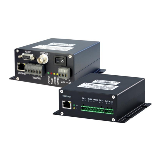
(700mA down to 10mA) HPSC4 Range2 Minimal Delay Time (7000mA down to 701mA) Range3 (40A down to 7001mA) Table 4: Minimum delay time for HPSC1 v2, HPSC2 and HPSC4 2.3. Physical Interfaces Configuration Ethernet (shown) USB2.0 RS-232 Trigger Output Trigger Input Open-collector, max. -
Page 11: Power Input
Trigger Inputs To physically trigger the strobe controllers by an external synchronization source, each device provides a count of input trigger lines (TRG), by a connector described in Table 6. Pin# HPSC1 HPSC1 v2 HPSC2 HPSC4 Phoenix Contact Phoenix Contact... - Page 12 Operating Limits Voltage Recommended operation voltage +0 to +24 VDC HIGH / Logical 1 > +3 VDC LOW / Logical 0 +0 to +1,4 VDC Undefined State > +1,4 to +3 VDC Absolute maximum +30 VDC The current draw for each input line is 6 to 10 mA. Table 7: HPSC-Series - Electrical Specification - Trigger Input(s) SMARTEK Vision | User Manual –...
- Page 13 Figure 2: Internal input trigger scheme for HPSC-Series SMARTEK Vision | User Manual – LED Strobe Controller Family | Doc. v2.2.1...
-
Page 14: Led Output
The LED connectors, as shown in Figure 1 and described in Table 8, provide the power output (LED) for the illumination to be driven by the controller. Scheme is shown in Figure 3. Pin# HPSC1 HPSC1 v2 HPSC2 HPSC4 Phoenix Contact... -
Page 15: Trigger Output
Trigger Output n - Table 9: Tigger Output (OUT) connector description HPSC-Series The limits of each line are shown in Table 10, the internal circuitry of the HPSC1 in Figure 4 and for HPSC1 v2, HPSC2 and HPSC4 in Figure 5. - Page 16 Figure 5: HPSC1 v2, HPSC2, HPSC4 – Trigger Output (OUT) – Schematics SMARTEK Vision | User Manual – LED Strobe Controller Family | Doc. v2.2.1...
-
Page 17: Mechanical Drawings
2.4. Mechanical Drawings 2.4.1. Dimensions of HPSC1 74,60 4,20 16,50 Figure 6: Dimensions of HPSC1 in mm SMARTEK Vision | User Manual – LED Strobe Controller Family | Doc. v2.2.1... -
Page 18: Dimensions Of Hpsc1 V2
2.4.2. Dimensions of HPSC1 v2 Figure 7: Dimensions of HPSC1 v2 in mm SMARTEK Vision | User Manual – LED Strobe Controller Family | Doc. v2.2.1... -
Page 19: Dimensions Of Hpsc2
2.4.3. Dimensions of HPSC2 Figure 8: Dimensions of HPSC2 in mm SMARTEK Vision | User Manual – LED Strobe Controller Family | Doc. v2.2.1... -
Page 20: Dimensions Of Hpsc4
2.4.4. Dimensions of HPSC4 6,40 Figure 9: Dimensions of HPSC4 in mm SMARTEK Vision | User Manual – LED Strobe Controller Family | Doc. v2.2.1... -
Page 21: Ipsc-Series
3. IPSC-Series 3.1. IPSC1 Figure 10: IPSC1 – Front panel view Specification IPSC1 Output channels Continuous, External Trigger, Internal Trigger, Operating Modes Software Trigger, External Switch 200V (pulsed) Max. Voltage 55V (continuous) Max. current pulse 20A @ 200V (depending on pulse width) Max. -
Page 22: Dimensions
3.1.1. Dimensions Figure 11: Dimensions of IPSC1 in mm and [inch] SMARTEK Vision | User Manual – LED Strobe Controller Family | Doc. v2.2.1... -
Page 23: Ipsc2
3.2. IPSC2 Figure 12: IPSC2 – Front panel view Specification IPSC2 Output channels Asynchronous Operation No timing independent channels Continuous, External Trigger, Internal Trigger, Operating Modes Software Trigger, External Switch 200V (pulsed) Max. Voltage 55V (continuous) Max. current pulse (depending on 10A @ 200V per channel (20A total) pulse width) Max. -
Page 24: Dimensions
3.2.1. Dimensions Figure 13: Dimensions of IPSC2 in mm and [inch] SMARTEK Vision | User Manual – LED Strobe Controller Family | Doc. v2.2.1... -
Page 25: Ipsc4
3.3. IPSC4 Figure 14: IPSC4 – Front panel view Specification IPSC4 Output channels Asynchronous Operation No timing independent channels Continuous, External Trigger, Internal Trigger, Operating Modes Software Trigger, External Switch 200V (pulsed) Max. Voltage 55V (continuous) Max. current pulse 10A @ 200V per channel (40A total) (depending on pulse width) Max. -
Page 26: Dimensions
3.3.1. Dimensions Figure 15: Dimensions of IPSC4 in mm and [inch] SMARTEK Vision | User Manual – LED Strobe Controller Family | Doc. v2.2.1... -
Page 27: Physical Interfaces
3.4. Physical Interfaces 3.4.1. Power Input The input power connector is located near the lower right corner of the IPSC front panel. All devices require an external 12V – 24V DC supply for operation, specified in Chapter 3. Description Phoenix Contact MSTB 2,5/ 3-ST-5,08 Type Power Supply (+12 to 24V DC) -
Page 28: Output Connector
3.4.2. Output Connector Figure 16: IPSC1/2/4 – Rear panel view with output connector Pin# IPSC1 IPSC2 IPSC4 Deltron DT13W3 1 2 3 4 5 Type 6 7 8 9 10 CH1-, Channel 1 - CH1-, Channel 1 - CH1-, Channel 1 - CH2-, Channel 2 - CH2-, Channel 2 - CH3-, Channel 3 -... - Page 29 Figure 17: Connecting scheme for LED output Figure 18: IPSC-Series - Trigger Output – Schematics SMARTEK Vision | User Manual – LED Strobe Controller Family | Doc. v2.2.1...
-
Page 30: Trigger Input
3.4.3. Trigger Input Pin# IPSC1 IPSC2 IPSC4 Phoenix Contact Phoenix Contact Phoenix Contact MSTB 2,5/ 6-ST-5,08 BNC-Connector MSTB 2,5/ 2-ST-5,08 MSTB 2,5/ 4-ST-5,08 TRIGGER TRIGGER 1 TRIGGER Type + or 1 Trigger Channel 1 + Trigger Channel 1 + Trigger Input 1 + Trigger Channel 2 + Trigger Input 2 + Not assigned... - Page 31 3.4.3.1. Opto-Isolated Trigger Source Figure 20 shows how an opto-isolated digital output of e.g. a camera can be connected to trigger an IPSC. The opto-coupler of the trigger source should be able to supply at minimum 20mA current and be rated for minimum 24V voltage. The shown pull down 1,2kΩ...
-
Page 32: Interfaces For Configuration
IEEE 802.3az Table 19: Supported Ethernet Standards Note: Using a 10/100Mbit network adapter for a direct connection to an IPSC and HPSC1 strobe controller makes it necessary to use cross-over cabling (HPSC1 v2, HPSC2 and HPSC4 excluded). 4.2. Serial RS-232 To connect a strobe controller to the PC using its RS-232 interface, a D-SUB DB9 cable (RS232) can be used. -
Page 33: Universal Serial Bus (Usb)
Note: The IPSCs and HPSCs series can be connected using a straight-through cable. 4.3. Universal Serial Bus (USB) Strobe controllers providing a USB interface can be connected by an USB1.x/2.0 cable providing Type-A to -B connectors. Pin no. Signal Table 21: USB-B connector assignment The USB connection is detected by the operating system as an USB-to-Serial converter and provides a serial COM-port. -
Page 34: Status Leds
Due to the different microcontroller architecture and differences in the boot- up routine, the HPSC1 and others (HPSC1 v2, HPSC2 and HPSC4) are slightly different in signaling. They are coded as shown in the following sections. -
Page 35: Ipsc-Series
5.2. IPSC-Series On the devices of the IPSC-series, there are 4 status LEDs on the front panel: Identifier Color Type IPSC1 IPSC2 IPSC4 POWER Green POWER FAULT FAULT STROBE Yellow1 STROBE ARMED Yellow2 ARMED Table 24: IPSC - Identification of status LEDs on different models When powering the device, POWER (green) and STROBE (yellow) LEDs are constantly ON, and the FAULT (red) LED is flashing for 5 seconds. -
Page 36: Error / Fault Codes
Input power supply voltage is too low, too high* or changed (> ±2.4V)* Cannot read DID from light head (IPSC-series only) *HPSC1 v2, HPSC2 and HPSC4 only Table 27: Error codes Depending on detected error code, the FAULT (IPSC) or Yellow LED (HPSC) is flashing in repeating sequences. -
Page 37: Getting Started
12V to 24V DC with at least 135W / 150W (3) Cable for communication: o Ethernet: Patch cable with RJ45 plugs; IPSC-Series/HPSC1: Direct connections to 10/100 Mbit network cards require a crossover cable o Serial: RS-232 straight-through cable with male to female 9-pole D-Sub plugs o USB: USB2.0 A-to-B cable... -
Page 38: Software Installation - Smartek Vision Sclib
(5) LED illumination o Note: The illumination must not be equipped with any additional internal / external control electronics! (6) Trigger source (optional) o 0 – 24V (voltage level for logical “1” from 3V). o IPSC-Series: 1,2kΩ / 0,5W resistor per trigger channel (optional for Hi/Hi-Z trigger sources) (7) PC with Microsoft Windows®... - Page 39 Step 3 – Establishing a connection: In the list of strobe controller, choose the device you want to connect to and press the button Connect Device. Alternatively, Ethernet strobe controller can be reached with their web-interface by typing the configured IP address into the address field of your web browser (e.g.
- Page 40 Apply and store the settings by pressing the button Send & Save which applies and stores the settings to the strobe controller. Further information on the configuration interface can be found in the following Chapter 7 - Device Configuration with the ScLibClient. SMARTEK Vision | User Manual –...
-
Page 41: Device Configuration With The Sclibclient
7. Device Configuration with the ScLibClient The ScLibClient is a graphical user interface application for strobe controller discovery, configuration and status. It is part of the ScLib which is a collection of software tools, programming samples and documentation to configure, run and integrate devices into user applications. -
Page 42: Find Devices
7.1. Find Devices Run the ScLibClient and click Find icon to start searching for devices. Figure 24: ScLibClient – Discovery Button 7.2. Discovery by Broadcast The usual way to identify available devices on Ethernet, RS-232 or USB is to search for them using a broadcast. -
Page 43: Ethernet Specific Discovery Options
(as shown in Figure 22), 16 addresses will be searched starting with the address in the left box. Note: Search for IP is currently supported only by HPSC1 v2, HPSC2 and HPSC4 devices and this will not find and IPSCx or HPSC1 Strobe controllers. Figure 27: ScLibClient – Search by IP Depending on the type of connection that is used towards the strobe controller, the results of a search might be different. - Page 44 In case no DHCP server is available in the network (peer-to-peer connection, switch, router without DHCP activated), the IP address of IPSCx and HPSC1 devices is set to the invalid IP address “0.0.0.0”, while HPSC1 v2, HPSC2 and HPSC4 devices receive an LLA address.
- Page 45 When the Strobe Controller is in a different network as the PC, it can be discovered using Search by IP and connected only if the gateway is correctly set. Gateway and DNS are currently only implemented on HPSC1 v2, HPSC2 and HPSC4 devices. SMARTEK Vision | User Manual – LED Strobe Controller Family | Doc. v2.2.1...
-
Page 46: Strobe Controller Status
7.4. Strobe Controller Status When a connection between ScLibClient and controller is established, all fields are read out in controller status. Controller status is defined in the lower left corner of the ScLibClient software: • Controller Model – shows the model of the strobe controller. •... -
Page 47: Running Modes
7.6. Running Modes All Strobe Controllers can be operated in different Running Modes, supporting pulsed and continuous DC current output. Figure 32: ScLibClient – Running Modes In pulse-controlled output modes, a Strobe Controller generates electrical impulses on the output. The output pulses in this mode can be triggered by an external, internal or software generated trigger source. -
Page 48: Off
7.6.1. The controller is in idle mode and does not respond to any input triggers. There is no voltage on any output line. 7.6.2. External Trigger In the External Trigger mode, the device is ready to accept external trigger signals and generates a very precise output pulse according to the user configuration. -
Page 49: Output Parameters
7.7. Output Parameters Using the output parameters, current and voltage can be configured individually for each channel. These parameters should only be applied carefully, meeting the specifications of the connected LED illumination. Too high output parameters can lead to permanent damage of the illumination. -
Page 50: Optimal Autosense
• Optimal Autosense – Enables / Disables Optimal Autosense for the internal power supply • Output Voltage – Voltage of the internal power supply, set by Optimal Autosense • Measured Voltage – Measured voltage at the internal power supply 7.7.1. Optimal Autosense Optimal Autosense is used to determine the optimal output voltage for the current set-up. -
Page 51: Controller Settings
Figure 34: ScLibClient – Controller Settings This feature is only supported by HPSC1 v2, HPSC2 and HPSC4 devices and comprises: • Max. Input Power – Limits the maximum recharging rate, used to limit the load on the external power supply while recharging internal capacitors. -
Page 52: Trigger Input
7.8. Trigger Input 7.8.1. Trigger Input Parameters With the trigger parameters, the timing options of the Trigger- (OUT) and LED-outputs (LED) are configured. Figure 35: ScLibClient – Trigger Parameters All parameters have a resolution of 1µs: • Trigger Edge – configuration of controller's input trigger edge. If the trigger edge is not the same between camera and strobe controller, asynchronization may occur between them. - Page 53 The Trigger Input(s) parameters are not used if the controller is in Continuous, External Switch or Off mode. The HPSC1 v2, HPSC2 and HPSC4 series provide different trigger Delay/On times for LED and OUT used for manual synchronization of camera and light source.
-
Page 54: Lightheads (Ipsc-Series Only)
7.9. Lightheads (IPSC-series only) To access the light heads options, click on the Light heads tab. Figure 37: ScLibClient - Configure Light head By using the Auto Detect button additional information is provided about the currently connected light heads. Only the light heads with digital light head signature can provide additional information. - Page 55 Figure 39: ScLibClient - Light head Information Controller – these parameters are changed when changing IP address of the strobe controller. These parameters are also read out in the controller status field: • Connection – IP address of the strobe controller •...
- Page 56 Figure 40: ScLibClient - Adding New Circuit Single Circuit Definition defines parameter for single circuit: • Circuit Description – defines the name of circuit. • User Data – circuit user data. • LED Serial Count – number of LEDs connected in series. •...
- Page 57 • Max DC Power (LED only) – maximal DC power which can run through single LED, with a value between 0 – 65535 [mW]. This value should be read out from the specifications of the LED • RC Thermal – time constant obtained by multiplication of thermal capacity and thermal resistance, with a value between 0 –...
- Page 58 • 1 – IPSC checks for AID at startup • 2 and 3 – IPSC checks for AID continuously all the time • 4 – IPSC checks for DID at startup • 5 – IPSC checks for DID and AID at startup •...
-
Page 59: Firmware Update
7.10. Firmware Update Firmware updates are applied to a device by flashing a binary firmware file, using the configuration interface (Ethernet, RS-232 or USB) of the Strobe Controller. The device must be in OFF mode, updates via Ethernet must be applied having a permanent IP address (not DHCP) set. - Page 60 Figure 47: Firmware update (4) 6) After re-programming has successfully finished, “PASSED” is indicated in text window. Depending on the device, this process can take a couple of minutes. When updating of new firmware finishes, simply close the dialog box. Figure 48: Firmware update (5) SMARTEK Vision | User Manual –...
-
Page 61: Other Features
7.11. Other features The following section shows further features of the ScLibClient configuration software. 7.11.1. Description Tab Open the Description tab to see major features, specifications and maximum ratings of the controller that is connected to the ScLibClient. Figure 49: Additional features – Description tab 7.11.2. - Page 62 Firmware Versions. In the table below, you can see some controller specific information. Controller Specific Information IPSCx ID Check Mode, Analog ID HPSC1 v2, HPSC2, HPSC4 FSBL Version, Format Version Table 29: Controller information SMARTEK Vision | User Manual – LED Strobe Controller Family | Doc. v2.2.1...
-
Page 63: Web Server
8. Web Server All Strobe Controllers with an Ethernet interface are accessible for configuration through a web interface. To gain access, just enter IP address (1) of the target device into your web browser. Use the web server to read and send parameters to the device (2), or to change its IP address (3). -
Page 64: Declarations Of Conformity
Internet Protocol Strobe Controller (IPSC), High Performance Strobe Controller (HPSC) Type of Equipment: IPSC1, IPSC2, IPSC4, HPSC1, HPSC1 v2, HPSC2, HPSC4 This equipment is in compliance with the essential requirements and other relevant provisions of the following EC directives: Reference No. -
Page 65: Fcc
Internet Protocol Strobe Controller (IPSC), High Performance Strobe Controller (HPSC) Type of Equipment: IPSC1, IPSC2, IPSC4, HPSC1, HPSC1 v2, HPSC2, HPSC4 Directive: FCC Part 15, Class A This equipment has been tested and found to comply with the limits for a Class A digital device, pursuant to part 15 of the FCC Rules. -
Page 66: Rohs Ii
Internet Protocol Strobe Controller (IPSC), High Performance Strobe Controller (HPSC) Type of Equipment: IPSC1, IPSC2, IPSC4, HPSC1, HPSC1 v2, HPSC2, HPSC4 This equipment is in compliance with the essential requirements and other relevant provisions of the following RoHS Directive 2011/65/EU. - Page 67 Version Date Description Corrected dimensions for IPSC4, HPSC4, descriptions updates, minor v2.2.1 2018-04-24 fixes v2.2.0 2018-01-18 Added specifications for HPSC1 v2 and HPSC2 v2.1.1 2017-04-28 Initial release SMARTEK Vision | User Manual – LED Strobe Controller Family | Doc. v2.2.1...
- Page 68 Contact Information Published by: Smartek d.o.o. Dobrise Cesarica HR-40000 Cakovec Croatia www.SMARTEK.vision Email: info@SMARTEKvision.com Tel: +385 (40) 493 805 Fax: +385 (40) 493 819 Copyright © 2018 by Smartek d.o.o. All rights reserved. For further information please contact our sales partners. SMARTEK Vision | User Manual –...
Need help?
Do you have a question about the HPSC1 and is the answer not in the manual?
Questions and answers