Advertisement
Table of Contents
- 1 Table of Contents
- 2 Safety Notes and Product Information
- 3 Installation of Energy Calculator
- 4 Installation of Temperature Sensors
- 5 Pulse Input Volume Pulses
- 6 Power Supply
- 7 Start-Up Operation
- 8 Expansion Modules
- 9 Communication
- 10 Display
- 11 Window
- 12 Simple Operation
- 13 Error Codes
- Download this manual
Instruction
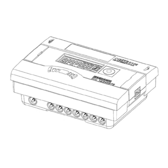
INFOCAL 8
Energy calculator
1.0
Table of contents
1.0
Table of contents .........................................................................................................................................................................................................................................................................1
2.0
Safety notes and product information ........................................................................................................................................................................................................................1
3.0
Installation of energy calculator .......................................................................................................................................................................................................................................2
4.0
Installation of temperature sensors ...............................................................................................................................................................................................................................3
5.0
Pulse input volume pulses ....................................................................................................................................................................................................................................................4
6.0
Power supply ..................................................................................................................................................................................................................................................................................5
7.0
Start-up operation ......................................................................................................................................................................................................................................................................6
8.0
Expansion modules ...................................................................................................................................................................................................................................................................6
9.0
Communication ...........................................................................................................................................................................................................................................................................7
10.0 Display .................................................................................................................................................................................................................................................................................................9
11.0 Simple operation ......................................................................................................................................................................................................................................................................10
12.0 Error codes ....................................................................................................................................................................................................................................................................................10
2.0 Safety notes and product information
Following instructions refer to the energy calculator.
The regulations on the use of energy meters must be observed! The
meter installation is only to be performed by an installation and/
or electrical contractor using personnel trained in the installation
and use of electrical equipment and familiar with the Low Voltage
Directive.
- The specified absolute temp. measuring range
is 0 ... 90°C/105°C/180°C
- The temperature range depends on calculator variant
- The exact temperature range is shown on the type plate
- The specified operating/ambient conditions are:
5...55 °C; max. 93% rel. humidity
- Protection class: IP54;
- Ambient temperatures below 35 °C ensures typical battery
lifetime
Danfoss District Energy
This installation guide is intended for trained personnel and
does not contain any basic working steps.
If the flow sensor is insulated with the pipeline,
the calculator must be accessible.
Safety Note
The seal on the energy calculator must not be damaged!
A damaged seal will result in immediate invalidation of the
factory warranty and verification. The cables supplied with the
calculator must not be shortened, extended or changed in any
other way.
VI.SH.L1.02
1
Advertisement
Table of Contents

Summary of Contents for Danfoss INFOCAL 8
-
Page 1: Table Of Contents
Instruction INFOCAL 8 Energy calculator Table of contents Table of contents ......................................................1 Safety notes and product information ............................................1 Installation of energy calculator ...............................................2 Installation of temperature sensors ...............................................3 Pulse input volume pulses ..................................................4 Power supply ........................................................5 Start-up operation ......................................................6 Expansion modules ....................................................6 Communication ......................................................7... -
Page 2: Installation Of Energy Calculator
Instruction INFOCAL 8 3.0 Installation of energy calculator Make sure the energy calculatorv is installed sufficiently far away from possible sources of electromagnetic interference (switches, electric motors, fluorescent lamps, etc...) The energy calculator should be installed in an accessible position for service and operating personnel. -
Page 3: Installation Of Temperature Sensors
Instruction INFOCAL 8 4.0 Installation of temperature sensors Handle the temperature sensors carefully! Installation in a ball valve: The sensor cables are fitted with coloured type labels: Tighten the plug screw with a torque of approx. 12 Nm Red (TH): sensor in hot line,... -
Page 4: Pulse Input Volume Pulses
Instruction INFOCAL 8 Installation of Installation of temperature sensors in 3 types of applications: temperature sensors, continued Calculator heating District heating/ boiler application Calculator heating / cooling Combined heating/ cooling application Calculator cooling Chilled water application 5.0 Pulse input volume pulses... -
Page 5: Power Supply
Calculator terminal 11 (-) 6.0 Power supply INFOCAL 8 can be powered from lithium battery (11 or 16 years life- time) or 230V AC / 24V AC mains unit supply. Battery 3.6 V DC lithium battery is fitted in the standard version. The battery is Caution not to be charged, replaced or short-circuited. -
Page 6: Start-Up Operation
Instruction INFOCAL 8 7.0 Start-up operation Once the calculator has been installed, the components (calculator, volume measuring component and both temperature sensors) must be sealed and the meter taken into operation. Bleed the system until the flow rate display is steady. -
Page 7: Communication
Instruction INFOCAL 8 9.0 Communication The calculator supports three communication channels. Additional to the radio communication two wired communication modules can be used, e.g. two M-Bus modules. The protocol of the two channels can be different but is preset at factory, whereby the radio telegram will have the same content than the module 2. - Page 8 Instruction INFOCAL 8 9.5 Pulse input function module Module for two additional meters. Pulse input 1 is marked as “I1- ”, Input frequency ≤ 8 Hz input 2 with “I2 - “. Pulse inputs can be programmed (IZAR@SET) with a value: 1, 2.5, 10, 25, 100, 250, 1000, 2500 litre per pulse.
-
Page 9: Display
Instruction INFOCAL 8 10.0 Display To show the data generated by the calculator in the display, various windows are provided as loop functions that can be called up in succession to display the system information associated with each The various display windows comprise up to several displays that window (e.g. -
Page 10: Simple Operation
Instruction INFOCAL 8 11.0 Simple operation The push-button is used to switch through the various displays. The button can be pressed for a short or long time. A short press of the button (< 3 seconds) switches to the next display within a loop and a long press (>... -
Page 11: Den-Smt/Pl
Instruction INFOCAL 8 Danfoss District Energy VI.SH.L1.02 DEN-SMT/PL... - Page 12 Instruction INFOCAL 8 VI.SH.L1.02 Produced by Danfoss A/S © 12/2014...
Need help?
Do you have a question about the INFOCAL 8 and is the answer not in the manual?
Questions and answers