Table of Contents
Advertisement
3G ENABLED VEHICLE RECORDER
Thank you for purchasing the TX4000 Vehicle Recorder.
Model: TX4000GE (with 3G module for WCDMA Band1(2,100MHz)/
Model: TX4000B (without 3G module)
Please ensure that you read and understand this USER GUIDE
and use it before connecting and installing this Recorder.
Please store the USER GUIDE in an easily accessible location.
TX4000
USER GUIDE
Band8 (900MHz))
VER 1.0.0 1
st
Edition
Advertisement
Table of Contents

Subscribe to Our Youtube Channel
Related Manuals for D-Teg TX4000B


Summary of Contents for D-Teg TX4000B
- Page 1 Thank you for purchasing the TX4000 Vehicle Recorder. Model: TX4000GE (with 3G module for WCDMA Band1(2,100MHz)/ Band8 (900MHz)) Model: TX4000B (without 3G module) Please ensure that you read and understand this USER GUIDE and use it before connecting and installing this Recorder.
-
Page 2: Table Of Contents
INDEX SAFETY ADVICE GPS RECEPTION CONTENTS INTRODUCTION FUNCTIONS LEDS &BUZZER SPECIFICATION INSTALLATION Operation – On Screen Display Axis Adjustments by Device Positions CONFIGURATION TOOL USER GUIDE SOFTWARE INSTALLATION INITIALIZE SD CARD DEVICE SETTINGS RECORD SETTINGS EVENT SETTINGS SYSTEM SETTINGS NETWORK SETTINGS DMS5 SETTINGS SOFTWARE USER GUIDE PC VIEWER SOFTWARE SETTINGS... -
Page 3: Safety Advice
SAFETY ADVICE CAUTION RISK OF ELECTRIC SHOCK DO NOT OPEN CAUTION: TO REDUCE THE RISK OF ELECTRIC SHOCK, DO NOT REMOVE COVER. NO USER-SERVICEABLE PARTS INSIDE. REFER SERVICING TO QUALIFIED SERVICE PERSONNEL. Please make sure you follow the safety advice/instructions given in the user guide. Caution RISK OF EXPLOSION IF BATTERY IS REPLACED BY AN INCORRECT TYPE. -
Page 4: Gps Reception
GPS RECEPTION Activate the product in an area without large buildings to improve GPS reception. The commercial purpose GPS has the average range error of more than 15 meters and the range error could be more than 100 meters due to environmental conditions like buildings, roadside trees etc. The temperature range for optimum operation of the GPS receiver in your car is -10 ~ 50°C. -
Page 5: Contents
CONTENTS Power Cable TX4000 Vehicle Recorder Audio/Video out cable Remote Controller (with double sided tape) Camera input cable GPS Antenna module 3G Antenna (only for TX4000GE) Wire Splice clip and Velcro Sticker... -
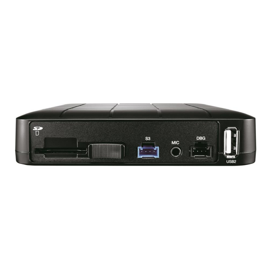
Page 6: Introduction
INTRODUCTION FRONT Debug port for Serial port development External Microphone input SD Memory Card Slot SD Locking Switch USB port for Wi-Fi dongle REAR 3G antenna connector Internal Microphone & Buzzer (Only for TX4000GE) Power input Camera input GPS input USB to Serial input Audio/Video output &... -
Page 7: Remote Controller
INTRODUCTION Remote Controller Green LED (Network) Blue LED (Record) Red LED (Warning) PANIC Button M1 button M2 button POWER CABLE Black (Ground) Red (Power Battery +) White (Power ACC + ) Alarm in/out Cable White (Alarm In1, Voltage on/off (3~70V)) Purple (Alarm In2, Voltage on/off (3~70V)) Green (Alarm In3, Voltage on/off (3~70V)) Gray (RPM) -
Page 8: Functions
FUNCTIONS Automatic Booting Make sure the main unit and all component are properly connected. Once the TX4000 has been wired to your car power source the TX4000 will be boot up, this will take around 30 seconds for the unit to be ready to record. NOTE: The unit will not start recording immediately after power on. - Page 9 FUNCTIONS G-Sensor Calibration G-Sensor Calibration is needed after installing the TX4000. 1. Set G-Sensor Axis using the configuration tool. 2. “selfadj.ini” should be in the config folder of the SD card. 3. Install the unit and park the vehicle on a flat surface . 4.
- Page 10 FUNCTIONS Parking Mode Recording With parking mode activated and on normal recording mode, the TX4000 will change to parking mode when the vehicle is not moving for more than 5 minutes, recording at 1 FPS. Live Screening With an external monitor attached, the TX4000 offers the option to screen video live.
-
Page 11: Leds &Buzzer Specification
LEDS & BUZZER SPECIFICATION... -
Page 12: Installation
INSTALLATION Park your vehicle on a flat level surface. Turn off the engine before installing the TX4000. 1) Find installation location for TX4000 like Glove box, under dash, trunk. 2) Use provided Velcro adhesive to secure TX4000 recorder. Velcro can be attached and detached freely. -
Page 13: Operation - On Screen Display
Operation – On Screen Display The following displays can only be seen when a monitor is connected. The default display is 2*2 with all cameras shown, to change, press [M2] button to select which camera to view. Each press will change the camera on display with the last option being all camera views. -
Page 14: Axis Adjustments By Device Positions
Axis Adjustments by Device Positions Driving Direction F: Front RR: Rear T: Top B: Bottom R: Right-side L: Left side 1) When device is in an upright position X: 0, Y: 0, Z:0 X: 0, Y: 0, Z:180 X: 0, Y: 0, Z:270 X: 0, Y: 0, Z:90 2) When device is in an upside down position X: 180, Y: 0, Z:0... - Page 15 Axis Adjustments by Device Positions 3) When device is in a sideway position with the TOP to the left X: 270, Y: 0, Z:0 X: 270, Y: 180, Z:0 X: 270, Y: 90, Z:0 4) When device is in a sideway position with the TOP to the right X: 90, Y: 0, Z:0 X: 90, Y: 180, Z:0 X: 90, Y: 90, Z:0...
- Page 16 Axis Adjustments by Device Positions 5) When device is in a sideway position with the TOP facing front X: 270, Y: 0, Z:90 X: 90, Y: 0, Z:270 X: 180, Y: 90, Z:0 6) When device is in a sideway position with the TOP facing rear X: 90, Y: 0, Z:90 X: 270, Y: 0, Z:270 X: 0, Y: 90, Z:0...
-
Page 17: Configuration Tool User Guide
CONFIGURATION TOOL USER GUIDE Configuration Tool TX4000 Software PC SYSTEM REQUIREMENT Recommended PC specifications for Configuration Tool Software Windows Vista. Windows 7, Windows 8/8.1 Core 2 Duo 2.5GHz or Higher 2GB or Higher Interface SD Memory Card Reader Install : 55MB or Higher Backup : 4GB or Higher Free space Display... -
Page 18: Software Installation
SOFTWARE INSTALLATION Please ask the Configuration Tool TX4000 Software to your distributor. 1. Double click [setup.exe] 2. Select the language 3. Select destination location 4. Select Start Menu Folder then follow the dialog box prompts. 5. The “Configuration Tool TX4000” icon will be displayed on your desktop. NOTE: To Un-install the Configuration Tool TX4000 Software Make sure the program is not running and open the ‘Control Panel’... -
Page 19: Initialize Sd Card
INITIALIZE SD CARD Click! To initialize the SD card quickly, click on the above icon and you will be presented with the following screen to choose the SD card to initialize. Click ‘OK’ when selected. On the following screen, check the ‘Quick Format’ button and uncheck the ‘Keep current configuration files’... -
Page 20: Device Settings
DEVICE SETTINGS Camera check box Check all the cameras you wish to use. Camera Title Use the alphabet and numbers to rename (max 10 digits) the cameras. The new names will be displayed on the all recordings. Video Type: Set the video type ”NTSC or PAL” Car Pulse Type: Select the vehicle’s car pulse type. -
Page 21: Record Settings
RECORD SETTINGS Resolution NTSC: D1 (720x480), HD (1280x720), FHD (1920x1080). PAL: D1 (720x576), HD (1280x720), FHD (1920x1080). FTS (Frame Rate) Adjust the frame rate from NTSC: 30fps, 15fps, 10fps, 5~1fps PAL: 25fps, 12fps, 10fps, 5~1fps Quality Adjust the picture quality from Standard, High, Super Record Frame Rate (FPS) Rules &... - Page 22 RECORD SETTINGS Record Mode • Continuous (Always recording when powered by DC 12/24V.) • Event (Automatically starts recording by G-sensor or Panic button or Alarm In.) • Dual (The continuous record fps is 1fps and Event record will work according to the Fps setting.) •...
-
Page 23: Event Settings
EVENT SETTINGS Event settings You can set the unit to record when triggered by the G-Sensor, Panic Button and GPS Speed Limit and Alarm Inputs. And you can set the Alarm out duration per each event. G-Sensor Sensitivity: The shock sensor sensitivity can be set to ‘Simple setting Mode’... - Page 24 EVENT SETTINGS Channel4(Camera4) Select record channel Channel1 (Camera1) Channel3(Camera3) Channel2(Camera2) Over Speed: When the vehicle speed over the speed limit more than 5seconds. System Warning: SD card error, Video loss, Video Standard error...
-
Page 25: System Settings
SYSTEM SETTINGS This option allows you to adjust the Time Zone, GPS Time synchronization, set your Vehicle No and also the Driver ID. SD Card Auto Format Feature: When the SD card has an error and cannot record, the card will be formatted and all data will be erased. -
Page 26: Network Settings
NETWORK SETTINGS Check Enable to use 3G connection. Adjust the settings like Dial No., APN, password, User ID, Authentication etc. Please refer to the Sim Card supplier website for these settings. -
Page 27: Dms5 Settings
DMS5 SETTINGS Set Domain/Static IP and Port number Default License Key is “DASKEY_001” And check the options • Transmit Live Tracking Data • Transmit Telematics Data (DRV) • Transmit Event Data. And then select events Please contact your distributor to set DMS5 setting it’s related with server. -
Page 28: Software User Guide
SOFTWARE USER GUIDE PC Viewer Software PC SYSTEM REQUIREMENT Recommended PC specifications for PC Viewer Software Windows Vista. Windows 7, Windows 8/8.1 Core 2 Duo 2.5GHz or Higher 2GB or Higher Interface SD Memory Card Reader Install : 55MB or Higher Backup : 4GB or Higher Free space Display... - Page 29 SOFTWARE INSTALLATION The PC Viewer Software is on the provided SD card. (Also available on our website.) 1. Connect the SD card into your PC (if your computer does not have and SD card slot use the USB SD card reader) and open the “My Computer” 2.
-
Page 30: Pc Viewer Software Settings
PC VIEWER SOFTWARE SETTINGS Viewing settings This setting is for the PC Viewer Software itself. To set the Recorder, refer to page 17. Click the ‘Password’ button. Password for the PC Viewer Software can be set with any number between 1000-9999. The ‘speed’... -
Page 31: Open The Sd Card
OPEN THE SD CARD Insert the SD card into your PC ② Select the SD card drive and ① Click “Select SD Card” icon click “OK” ③ Click “Open SD Card” The playback file list and “Continuous” and “Event” tap is displayed on the right side of the screen. You can hide the playback list by clicking the close icon. -
Page 32: Open Files
OPEN FILES If you want to play a specific file that has been backed up on the PC or SD Card, Click the “Open files” icon “Open files” icon Select the MDT file you want to play and click “Open”. The image of the selected file will then be displayed and you can click the “Play”... -
Page 33: Playback
PLAYBACK Camera title - Resolution Record Mode G-Sensor value GPS Speed Time Display Frame / Total frames number Vehicle No & Driver ID... - Page 34 PLAYBACK Reverse Play Previous Next Pause Image Image Capture Screen Record Video Volume Playback Speed Control Alarm Indicator Playback control bar...
-
Page 35: Drive Data
DRIVE DATA “Drive Data” icon The default setting only displays the G-sensor graphs but other information may be added by checking the boxes in the upper part of the screen. G-Sensor: (X axis: red, Y axis: green, Z axis: blue, based on the positioning of the main unit) is shown with the data reference point zero-point calibrated and positive shocks as (+) and negative shocks as (-). -
Page 36: Tracking Map
TRACKING MAP “Tracking Map” icon The route taken will be displayed on the Google map. The playback position will be shown on the map with the orange arrow. The blue markings show the route taken. To see the route and position on the Google map, the GPS data should be recorded with video. -
Page 37: Event Search
EVENT SEARCH “Event Search” icon The “Event Search” help to find a specific data quickly. Select “Search Range” and select “Search Conditions” And then click Search button. Choose an event from the searched list and click “Go to Video” to see the video. -
Page 38: Privacy Settings
PRIVACY SETTINGS “Privacy Settings” icon Set the mosaic area on the video for privacy protection. When backing up the data as a JPG or AVI format and playing in the Viewer software, you are able to make a mosaic processing on the area you have set. -
Page 39: Save Jpeg And Mp4 File
SAVE JPEG AND MP4 FILE Pause the playback and click “Save JPG” icon to make JPG images. “Save JPG” icon Pause the playback and click “Save MP4 Video” icon to make a MP4 file. “Save MP4 Video” icon... -
Page 40: Print Image
PRINT IMAGE Pause the playback and click “Print Image” icon. “Print Image” icon Type Subject and Comments1 and Comments 2 Alter the printer settings to change paper size/orientation etc. -
Page 41: Backing Up Files
BACKING UP FILES Back up the recorded data on your PC. There is an option to store data by type to easy management of data. “Backup Data” icon The start time is when the video was paused and cannot be changed once you start this process. -
Page 42: Backup Data List And Export
BACKUP DATA LIST AND EXPORT You can use the data backup list to play data files easier that have been backed up. “Backup Data List and Export” icon Choose the folder where the backup files are at the bottom of the screen. (It will automatically show the last folder that was accessed.) Then, select the type by scrolling down the options. -
Page 43: Specification
SPECIFICATION CH1, CH2: 5V 1080P or 720p AHD camera in Video In CH3: 5V 720P AHD camera in CH4: 5V D1 camera in Audio In 1CH (Internal or External Microphone) AV Out 1 Video out, 1 Audio out Band support WCDMA Band1(2,100MHz)/ Band8 (900MHz) Max Data Rate UL:5.76Mbps, DL : 7.2Mbps... -
Page 44: Appendix Recording Time Table
APPENDIX Recording time table DRV file size Reserved sp Space for Video / Audio (MB) ace for hours Size 16GB 32GB 64GB 128GB 256GB overwriting 106.8MB 15,593 31,593 63,593 127,593 255,593 748 MB 14,952 30,952 62,952 126,952 254,952 300 MB 1068 MB 14,632 30,632... -
Page 45: Appendix Upgrade
APPENDIX (Upgrade) NOTE: To get the upgrade firmware, please contact your local distributor. 1. Prepare Firmware Make a folder called [program] on the SD root folder as shown below, Copy “XXXXXX_x.x.x.img” file to the SD card [program] folder. 2. Upgrade TX4000 Insert the prepared SD card to TX4000 unit and turn on the power. -
Page 46: Technical Support And Warranty
Technical Support & Warranty TECHNICAL SUPPORT For Technical Support, please contact your local distributor. LIMITED WARRANTY This product is supplied with 1 year warranty. The Warranty excludes products That have been misused, (including accidental damage) and damage caused by normal wear and tear. In the unlikely event that you encounter a problem with this product, it should be returned to the place of purchase. - Page 47 Optional Item Model Descriptions SH-300 Locking Steel Housing for TX4000 Dimension : 155.00 x 130.00 x 24.00 mm, 330g MIC-100 External Omni-directional microphone with 8.5 ft. cable DTR-100A 1.3Mega-Pixel 1/4" CMOS Sensor, Resolution: 720P, Angle of View: 100° Min. Illumination: 0.5 lux Operating Temperature: -10°C ~ 55°C Input Voltage: DC 12V 31mm(W) x 33.5mm(H) x 25mm(D)
- Page 48 http://www.d-teg.com...
Need help?
Do you have a question about the TX4000B and is the answer not in the manual?
Questions and answers