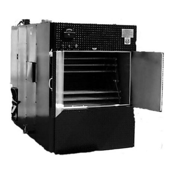
J&R 700E Operation And Service Manual

J&R 700E Operation And Service Manual

Oyler barbecue pit
Table of Contents

Advertisement

OYLER BARBECUE PIT
MODEL 700E/ 1300E
OPERATIONS AND SERVICE MANUAL
J&R M
ANUFACTURING,
820 W. Kearney
Suite B
Mesquite, Texas
I
NC.
75149
(972) 285-4855
(Texas)
(800) 527-4831
(50 states & Canada)
(972) 289-0801
(Parts and Service)
(972) 288-9488
(Fax)

Advertisement

Table of Contents
loading

Summary of Contents for J&R 700E

  • Page 1 OYLER BARBECUE PIT MODEL 700E/ 1300E OPERATIONS AND SERVICE MANUAL J&R M ANUFACTURING, (972) 285-4855 (Texas) 820 W. Kearney (800) 527-4831 (50 states & Canada) Suite B (972) 289-0801 (Parts and Service) Mesquite, Texas 75149 (972) 288-9488 (Fax)
  • Page 2 SN _______________...
  • Page 3 WARNINGS! Disposal of Ashes Ashes should be placed in a metal container with a tight-fitting lid. J&R offers ash carts suitable for this purpose. The closed container of ashes should be placed on a noncombustible floor or on the ground, well away from all combustible materials, pending final disposal.
  • Page 5 OYLER BARBECUE PIT 700E 1300E ODELS OPERATIONS AND SERVICE MANUAL MANUFACTURED BY: J & R MANUFACTURING, INC. Rev. 06-17...
  • Page 7 FIGURE 5B SMOKESTACK INSTALLATION – F IGURE 6 C OOKING M ODE F IGURE 7 –DAMPER ACTUATORS M ODEL 700E & 1300E W IRING SCHEMATICS – 240 VOLT T HERMOSTAT , ACTUATOR, AND TIMER M ANUALS W ARRANTY W OOD S OURCE...
  • Page 8 YLER ARBECUE 700E / 1300E ODEL COOK MODES The “E” version of the Oyler Barbecue Pit Model 700/1300 uses electric heating elements in addition to wood fuel for the cooking heat source. Additional controls allow the operator to cook in one of two “Cook” Modes, “Standard” or “Dual Fuel”.
  • Page 9 COOK AND HOLD MODE The difference between this mode and “Cook” mode (“Standard or “Dual Fuel”) is the temperature control is shifted away from the primary thermostat to a fixed secondary (or Hold) thermostat after the operator set timer, located on the instrument panel, counts down.
  • Page 11 ODEL ODEL SHIPPING The unit will be shipped fully assembled. A Model 700E will weigh 4,200 pounds and a Model 1300E will weigh 6,600 pounds. The meat racks will be packed inside the cooking compartment. If you ordered a smokestack kit, it will either be packed inside, or shipped on a separate pallet.
  • Page 12 EXTERIOR INSTALLATION There are two types of exterior installations. The unit can be placed entirely outside or you may wish to have only the front part of the unit inside your building. In either case, the unit should be painted and the top seams sealed for exterior installation.
  • Page 13 Venting Requirements Our barbecue ovens are listed under multiple standards, including U.L. 737 (Fireplace Stoves), U.L. 2162 (Commercial Wood-Fired Baking Ovens), and U.L. 391 (Solid-Fuel and Combination-Fuel Central and Supplementary Furnaces. These listing provide two alternatives for exhausting our units: direct venting and exhaust hood venting. In all cases, it is imperative to obtain the approval of the AHJ (Authority Having Jurisdiction).
  • Page 14 Air Balance The building air balance is very important to the proper operation of your Oyler Pit. The Oyler design is based on the induction of air into the pit due to the “stack effect” of the chimney. The “stack effect” is the term used to describe the upward airflow created in a chimney based on the chimney height and the temperature difference between the bottom (inlet) and top (discharge).
  • Page 15 For proper design of a hood over our ovens, please refer to Figure 5A (Figures 5 and 5A depict a single canopy hood design). It is very important that the filter bank be located toward the rear of the unit (near the chimney connector). This simulates the natural-draft of a chimney above the chimney connector for which these units were engineered to control both temperature and smoke.
  • Page 16 YOU MUST ALWAYS have a rack installed in the lowest position of the hanger to avoid a rack jam. Model 700E The hangers for Model 700Es will be one of the following: Type 1. Triple hangers with three pairs of wire pegs per hanger (starting mid- 2017: see photo on the next page.
  • Page 17 (no removal necessary). Hooks or pegs go here for Type 1 Corner “void” “Nib” Model 1300E Rack Model 700E Rack Here for Types 2 and 3 Model 700E Type 1 Model 700E Type 2 Model 700E Type 3 Model 1300E...
  • Page 18 OPERATING INSTRUCTIONS MODEL 700E AND MODEL 1300E START-UP After the pit is installed, leveled, stacked, and connected to the electrical supply, check for proper operation: Turn the thermostat set point above and then below the actual temperature. The combustion air damper on the firebox should open and close.
  • Page 19 MEAT LOADING The first time the pit is fired, it is recommended that you allow it to operate or several hours while empty. This allows any residues (oil, paper, etc. to be removed. After this is done, you may load meat onto the racks. Take care when loading to keep the load balanced.
  • Page 20 250° F. 2 Hours *Sensed at the midpoint of the pit. **These cooking times are based on a full loading in a Models 700E and 1300E Pits (18 racks) and apply to the meat on the bottom racks. With decreased loadings, the cooking times should be reduced.
  • Page 21 MAINTENANCE AND CLEANING MODEL 700E AND MODEL 1300E PIT DESIGN Smoke and heat from the firebox enter the cooking compartment through refractory-lined flues. Smoke exits this area through a separate flue. Temperature control is effected by regulating the flow of combustion air into the firebox and the discharge from the cooking compartment.
  • Page 22 Leave the racks in place and fill the pit with a hot water/oven cleaner solution up to the middle of the exit flue opening. Heat the pit up to 250° and allow the racks to revolve. Continue for at least 4 hours, drain and rinse the pit thoroughly.
  • Page 23 Check the evacuation (bypass) system for proper operation. Open the front doors and make sure that the bypass dampers operate properly. They should seal tightly when the front doors are closed and latched (and the “Evac” switch, if the pit is equipped with one, is off). Clean excess carbon build-up or residue from the rear area of the pit, including the inside of the access door above the firebox, the firebox door and the area around the firebox door.
  • Page 24 TROUBLESHOOTING Combustion air damper and exit flue fails to open and close. ROBLEM One of the following components is inoperative: AUSES the thermostat, the damper motor, or the linkage between the motor and the dampers. ROCEDURE Open the access door to flues and dampers. (see Figure 1) Make sure that the linkage is attached to the motor and that all pivot pins are in place.
  • Page 25 ROCEDURE Proceed as in problem 1, if the combustion damper and exit flue are not opening. Verify that the exit flue is clean. If the problem still exists, make sure that the two large bypass dampers are sealing against their respective gasketed seats.
  • Page 26 Rotisserie does not revolve. ROBLEM One or more of the following: AUSES motor failure, circuit failure, gearbox failure, broken chain, loose sprocket, or the overload device has tripped. ROCEDURE Inspect the cooking compartment to be sure that the rotisserie assembly has not jammed. If the assembly is okay and the load is evenly balanced, turn the rotisserie switch to the “off”...
  • Page 27 Shut the pit circuit off and remove the motor and gearbox assembly by removing the bolts holding the gearbox onto the base plate. Remove the motor from the gearbox and inspect the coupling between the two. If it is not broken, replace the gearbox.
  • Page 28 ROCEDURE Shut the pit circuit off and tag it. Open the motor/gearbox access door. Inspect the chain. It should not have excessive slack over or under the gearbox sprocket. If it does, remove any meat that might be on the racks and loosen the four bolts securing the gearbox to its base.
  • Page 29 Oyler Interior Installation with Direct Vent Figure 1 LEGEND 1. RAIN CAP 8. FIREBOX DOOR 2. COUNTER FLASHING 9. CONCRETE PAD (RECOMMENDED) 3. ROOF JACK 4 TO 6 INCHES HIGH OR USE STEEL BASE 4. SMOKESTACK 10. DRAIN VALVE 5. ACCESS PANEL TO GEARBOX, MOTOR, GREASE FITTINGS 11.
  • Page 31 Oyler Through-the-Wall Installation with Direct Vent Figure 3...
  • Page 33 Oyler With Exhaust Hood Vent Unit shown is a Model 700-Left Firebox Figure 5...
  • Page 35 (Single wall smokestack- only for use when no combustibles are present) Figure 5B...
  • Page 37 Oyler Pits utilize two damper actuators, one for temperature control and one for the “ Evac” mode. Older units have Barber-Colman actuators and newer units have Schneider Electric actuators. They are identical, other than the name, as Schneider acquired Barber-Colman. Instructions for the actuators are included in this manual (see the Thermostats and Actuator Manuals section).
  • Page 43 IM800-06 800 Series Indicating Temperature Controls U N I T E D E L E C T R I C Types 800, T800, 802 C O N T R O L S Please refer to IMT120 for Explosion Proof Types Installation and Maintenance 820E and 822E Instructions...
  • Page 44 WIRING Part II - Adjustments Tools Needed (Refer to Figure 3) DISCONNECT ALL SUPPLY CIRCUITS BEFORE WIRING. ELECTRICAL RATINGS STATED IN LITERATURE AND ON NAMEPLATE SHOULD 5/64” Allen Wrench NEVER BE EXCEEDED. OVERLOAD ON A SWITCH CAN CAUSE FAILURE 5/16” Open End Wrench (2 required) ON THE FIRST CYCLE.
  • Page 45 General Layout Adjusting Thermometer Type T800 Use the in-process adjustment to check the control. Differences between the test instrument and the thermometer can be corrected by turning the zero adjustment “C” per Figure 3 on the thermal assembly. Turning in lowers SWITCH 1 indicated reading.
  • Page 51 MAx-305 & MAx-318 Series MAx-405 Through MAx-419 Series Two-Position Actuators General Instructions Application For two-position operation of dampers, valves, and other equipment which require the return to normal position upon power interruption. Hazardous location models offer a sturdy cast aluminum case with bolted cover. They have two 3/4" pipe tapped openings for joints with rigid metal conduit.
  • Page 52 SPECIFICATIONS Actuator Inputs Connections: Coded screw terminals. Control Circuit: Two-wire. Power Input: See Table-1. Actuator Outputs Torque: See Table-1. Shaft Rotation: MA-305, MA-405, MA6-305, MA6-405, CW 180° when power is applied. MA-318, MA-41x, MAx-318, MAx-41x, CW 180° when power is applied. Spring Return: CCW to the original position when the actuator is de-energized.
  • Page 53 TYPICAL APPLICATIONS (Wiring Diagrams) MA-305 MA-405 Thermostat Series Actuator or Switch L1 or H Motor Field Coil L2 or G Actuator rotates 180 ° CW when thermostat or switch contacts are closed. Actuator spring returns when thermostat or switch contacts are open. Aux.
  • Page 54 Table-3 Power Wire Selection. Wire Size Maximum Run Actuator Series ft (m) 122 (37) MA-305 191 (58) 305 (93) MA-405 2800 (853) 44 (13) MA-318 68 (21) 110 (34) 950 (290) MA-416, MA-418, MA-419 1580 (482) a Each run has two wires. b The length given is for a maximum two-wire run, for one actuator.
  • Page 57 H3CR H3CR Solid-State Timer H3CR RANGE SELECTION Operating mode display window Power indicator (green LED) flashes when timer operates, Operation mode selector lit when timer ON-delay stops operating Repeat cycle/signal OFF start B2: Repeat cycle/signal ON start Output indicator C: Signal ON/OFF-delay (red LED) D: Signal OFF-delay E: Interval...
  • Page 58 Revised 04-01-2017 WARRANTY J & R MANUFACTURING, INC. warrants its equipment against defective parts and workmanship under normal use and when installed in accordance with manufacturer’s recommendations for a period (after date of shipment*) of twelve ( 12 ) months on parts and ninty (9 0) days on labor with the following provisions: 1.
  • Page 59 Remember to contact J&R for any additional information you need or to order replacement parts or accessories. Accessories include: Ash Carts Wood Carts Ash Rakes Contact J&R: 972-285-4855 (Main) 972-289-0801 (Parts and Service) 800-527-4831 (Toll Free-U.S and Canada) sales@jrmanufacturing.com www. jrmanufacturing.com For firewood, we recommend: Arnold Bros.

This manual is also suitable for:

1300e

Table of Contents