Advertisement
Visit www.carrier.com
Installation and Start-Up Instructions
NOTE: Read the entire instruction manual before starting the
installation.
SAFETY CONSIDERATIONS
Improper installation, adjustment, alteration, service, maintenance,
or use can cause explosion, fire, electrical shock, or other
conditions which may cause death, personal injury, or property
damage. Consult a qualified installer, service agency, or your
distributor or branch for information or assistance. The qualified
installer or agency must use factory-authorized kits or accessories
when modifying this product. Refer to the individual instructions
packaged with the kits or accessories when installing.
Follow all safety codes. Wear safety glasses, protective clothing,
and work gloves. Use quenching cloth for brazing operations.
Have fire extinguisher available. Read these instructions thor-
oughly and follow all warnings or cautions included in literature
and attached to the unit. Consult local building codes and National
Electrical Code (NEC) for special requirements.
Recognize safety information. This is the safety-alert symbol
When you see this symbol on the unit and in instructions or
manuals, be alert to the potential for personal injury.
Understand the signal words DANGER, WARNING, and CAU-
TION. These words are used with the safety-alert symbol. DAN-
GER identifies the most serious hazards which will result in severe
personal injury or death. WARNING signifies hazards which
could result in personal injury or death. CAUTION is used to
identify unsafe practices which would result in minor personal
injury or product and property damage.
Before installing, modifying, or servicing system, main elec-
trical disconnect switch must be in the OFF position. There
may be more than 1 disconnect switch. Lock out and tag
switch with a suitable warning label. Electrical shock can
cause personal injury or death.
R-410A systems operate at higher pressures than standard
R-22 systems. Be certain that service equipment is rated for
R-410A. Some R-22 service equipment may not be accept-
able. Check with your distributor.
INSTALLATION RECOMMENDATIONS
NOTE: In some cases noise in the living area has been traced to
gas pulsations from improper installation of equipment.
1. Locate unit away from windows, patios, decks, etc. where unit
operation sound may disturb customer.
2. Ensure that vapor and liquid tube diameters are appropriate to
capacity of unit.
3. Run refrigerant tubes as directly as possible by avoiding
unnecessary turns and bends.
Manufacturer reserves the right to discontinue, or change at any time, specifications or designs without notice and without incurring obligations.
Book 1 4
PC 101
Catalog No. 563-804
Tab 5a 5a
Deluxe 13 SEER Split-System
.
4. Leave some slack between structure and unit to absorb
vibration.
5. When passing refrigerant tubes through the wall, seal opening
with RTV or other pliable silicon-based caulk. (See Fig. 2.)
6. Avoid direct tubing contact with water pipes, duct work, floor
joists, wall studs, floors, and walls.
7. Do not suspend refrigerant tubing from joists and studs with a
rigid wire or strap which comes in direct contact with tubing.
(See Fig. 2.)
8. Ensure that tubing insulation is pliable and completely sur-
rounds vapor tube.
9. When necessary, use hanger straps which are 1 in. wide and
conform to shape of tubing insulation. (See Fig. 2.)
10. Isolate hanger straps from insulation by using metal sleeves
bent to conform to shape of insulation.
When outdoor unit is connected to factory-approved indoor unit,
outdoor unit contains system refrigerant charge for operation with
indoor unit of same size when connected by 15 ft of field-supplied
or factory accessory tubing. For proper unit operation, check
refrigerant charge using charging information located on control
box cover and/or in the Check Charge section of this instruction.
IMPORTANT: Maximum liquid-line size is 3/8-in. OD for all
residential applications including long line.
IMPORTANT: Always install the factory-supplied R-410A heat
pump (bi-flow) liquid-line filter drier. If replacing the filter drier,
refer to Product Data Digest for appropriate part number. Obtain
Printed in U.S.A.
Form 38YXA-1SI
Heat Pump with R-410A
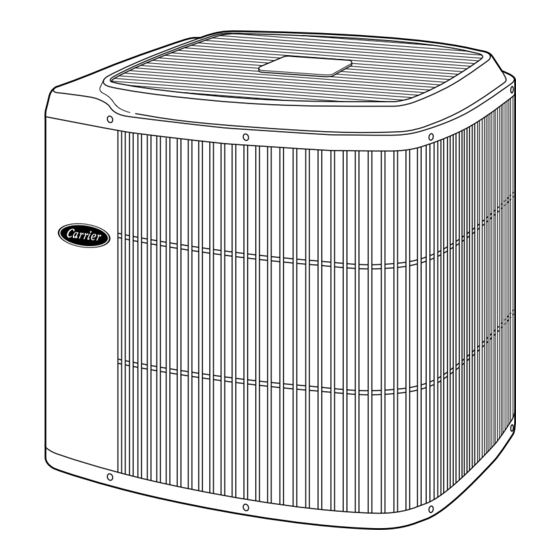
Fig. 1—Model 38YXA
Pg 1
11-97
38YXA
A92446
Replaces: New
Advertisement
Table of Contents

Related Manuals for Carrier 38YXA


Summary of Contents for Carrier 38YXA
- Page 1 TION. These words are used with the safety-alert symbol. DAN- A92446 GER identifies the most serious hazards which will result in severe Fig. 1—Model 38YXA personal injury or death. WARNING signifies hazards which could result in personal injury or death. CAUTION is used to 4.
-
Page 2: Installation
NOTE: Avoid contact between tubing and structure 3 /8 - IN. DIA TIEDOWN KNOCKOUTS IN BASEPAN (2) PLACES OUTDOOR WALL INDOOR WALL CAULK LIQUID TUBE VAPOR TUBE INSULATION THROUGH THE WALL JOIST ″ VIEW FROM TOP HANGER STRAP (AROUND VAPOR INSULATION TUBE ONLY) A97548... -
Page 3: Fan Coils
FAN COILS If indoor unit (fan coil) comes factory equipped with a bi-flow hard shutoff TXV specifically designed for R-410A, no TXV change is required. If TXV installation is required, refer to TXV kit Installation Instructions for details on TXV installation. Step 7—Check Defrost Thermostat Check defrost thermostat to ensure it is properly located and securely attached. - Page 4 tial capacity and performance losses can occur. Follow the FEEDER TUBE recommendations in the Application Guideline and Service STUB TUBE Manual for Residential Split-System Air Conditioners and Heat Pumps Using R-410A Refrigerant to minimize losses. Refer to Table 1 for field tubing diameters. Refer to Table 2 for accessory requirements.
- Page 5 LEAK CHECKING SWEAT/ FLARE ADAPTER Leak test all joints in indoor, outdoor, and refrigerant tubing. EVACUATE REFRIGERANT TUBING AND INDOOR COIL TEFLON SEAL Never use the system compressor as a vacuum pump. Refrigerant tubes and indoor coil must be evacuated using the recommended deep vacuum method of 500 microns.
- Page 6 DISCONNECT EVACUATE PER N. E. C. AND/OR LOCAL CODES CONTACTOR BREAK VACUUM WITH DRY NITROGEN FIELD POWER WIRING WAIT EVACUATE FIELD GROUND WIRING BREAK VACUUM WITH DRY NITROGEN GROUND A91056 WAIT Fig. 12—Line Power Connections Use No. 18 AWG color-coded, insulated (35°C minimum) wire. If EVACUATE thermostat is located more than 100 ft from unit, as measured along the control voltage wires, use No.
- Page 7 IMPORTANT: When using outdoor thermostats, W 2 must be CONNECTION energized when requesting supplemental heat. A97563 A97564 Fig. 13—Typical 24-v Circuit Connections using Carrier Model HP Thermostat with Fan Coils and No Outdoor Thermostat, 1 Outdoor Thermostat, or 2 Outdoor Thermostats...
- Page 8 OTHER BRAND FA, FB, FX HEAT OTHER BRAND HEAT FA, FB, FX OUTDOOR PUMP HP THERMOSTAT FAN COIL HP THERMOSTAT FAN COIL PUMP THERMOSTAT 24 VAC HOT 24 VAC HOT 24 VAC COM 24 VAC COM HEAT STAGE 2 HEAT STAGE 2 COOL/HEAT STAGE 1 COOL/HEAT...
- Page 9 TEMPERATURE SENSOR TEMPERATURE SENSOR SENSOR CONNECTION CONNECTION SENSOR A97538 A97539 Fig. 15—Typical 24-v Circuit Connections using Carrier Model DF Thermostat with Single- or 2-Stage Furnace CARRIER PROGRAMMABLE FV4A HEAT THERMOSTAT FAN COIL PUMP MODEL 2S J1 JUMPER 24 VAC HOT...
- Page 10 RVS COOLING O/W2 NOT USED Y1/W2 24 VAC COM NOT USED TROUBLE OPTIONAL OUTDOOR SENSOR CONNECTION A97568 Fig. 17—Typical 24-v Circuit Connections using Carrier Model HP Thermostat with Smart Heat and No Outdoor Thermostat, 1 Outdoor Thermostat, or Supplemental Heat Relay...
- Page 11 FA, FB, FX OTHER BRAND FAN COIL WITH HEAT FA, FB, FX HP THERMOSTAT SMART HEAT PUMP OTHER BRAND FAN COIL WITH HEAT HP THERMOSTAT PUMP SMART HEAT 24 VAC HOT 24 VAC HOT 24 VAC COM 24 VAC COM COOL/HEAT STAGE 1 COOL/HEAT...
-
Page 12: Wiring Diagram Notes
WIRING DIAGRAM NOTES: 1. CARRIER THERMOSTAT WIRING DIAGRAMS ARE ONLY ACCURATE FOR MODEL NUMBERS TSTAT _ _ _ _ _ _ _. 2. WIRING MUST CONFORM TO NEC OR LOCAL CODES. 3. ALL UNITS ARE EQUIPPED WITH PRESSURE SWITCHES, TEMPERATURE SWITCH, AND 5-MINUTE COMPRESSOR CYCLE PROTECTION. - Page 13 Defrost NOTE: Length of defrost cycle is dependent on the length of time it takes to remove screwdriver from test pins after reversing valve The defrost control is a time/temperature control which includes a has shifted. field-selectable (quick-connects located at board edge) time period 7.
-
Page 14: Care And Maintenance
Table 4—Required Liquid-Line Temperature (°F) HEATING CHECK CHART PROCEDURE To check system operation during heating cycle, refer to the Heat REQUIRED SUBCOOLING TEMPERATURE LIQUID PRESSURE Pump Charging Instructions label on outdoor unit. This chart (°F) AT SERVICE VALVE (PSIG) indicates whether a correct relationship exists between system operating pressure and air temperature entering indoor and outdoor units. - Page 15 R-410A—QUICK REFERENCE GUIDE R-410A refrigerant operates at 50-70 percent higher pressures than R-22. Be sure that servicing equipment and replacement • components are designed to operate with R-410A. R-410A refrigerant cylinders are rose colored. • R-410A refrigerant cylinders have a dip tube which allows liquid to flow out of cylinder in upright position. •...
-
Page 16: Service Training
[ ] Classroom Service Training A94328 Copyright 1997 CARRIER Corp. • 7310 W. Morris St. • Indianapolis, IN 46231 38yxa1si Manufacturer reserves the right to discontinue, or change at any time, specifications or designs without notice and without incurring obligations.
Need help?
Do you have a question about the 38YXA and is the answer not in the manual?
Questions and answers