Sign In
Upload
Download
Table of Contents
Contents
Add to my manuals
Delete from my manuals
Share
URL of this page:
HTML Link:
Bookmark this page
Add
Manual will be automatically added to "My Manuals"
Print this page
×
Bookmark added
×
Added to my manuals
Manuals
Brands
OTT Manuals
Data Loggers
netDL 500
Operating instructions manual
OTT netDL 500 Operating Instructions Manual
Ip datalogger
Hide thumbs
1
2
Table Of Contents
3
4
5
6
7
8
9
10
11
12
13
14
15
16
17
18
19
20
21
22
23
24
25
26
27
28
29
30
31
32
33
34
35
36
37
38
39
40
41
42
43
44
45
46
47
48
49
50
51
52
53
54
55
56
57
58
59
60
page
of
60
Go
/
60
Contents
Table of Contents
Bookmarks
Table of Contents
Table of Contents
Scope of Supply
Order Numbers and Version Code
General Safety Information
About These Operating Instructions
Introduction
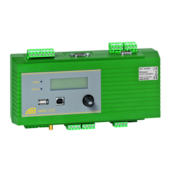
Overview of the OTT Netdl IP Datalogger
Overview: Starting up the OTT Netdl Unit
Installing the OTT Netdl Unit
Attaching the OTT Netdl Unit
Device Versions B . . and C . . : -30 °C up to +70 °C
Attaching the Datalogger
Locations of the Screw Terminal Strips and RS-232 Interfaces
Connecting Sensors Having an RS-485 Interface (2-Wire)
Connecting Sensors Having an SDI-12 Interface
Connecting Sensors Having a Pulse Output
Connecting Equipment Having a Status Output
Connecting Sensors Having a Voltage Output
Connecting Sensors Having a Current Output
Connecting the Pt 100 Temperature Sensor
Connecting Sensors Having a Potentiometer (5 Kohms)
Connecting Sensors Having an RS-232 Interface
Connecting Switching Contacts
Connecting 4-20 Ma Outputs
Connecting Status Outputs
Connecting the Power Supply to the OTT Netdl Unit
Connecting the GSM Cellular Radio Antenna and Inserting the SIM Card
Connecting the GSM Cellular Radio Antenna
Connecting External Communication Equipment
Connecting an Ethernet LAN or DSL Router
Connecting to the USB Device Interface
Setting OTT Netdl Operating Parameters
Installing the OTT Data Logger Operating Program
Establishing the PC/OTT Netdl Communication Link (on Site)
Introduction: Setting OTT Netdl Operating Parameters
Operating/Configuring the OTT Netdl Unit on Site
Determining and Displaying Instantaneous Values (Observer Function)
Entering Observer Texts (Extended Observer Function)
Scaling Instantaneous Values/Stored Values (Set Offset)
Displaying/Setting Date and Time
Entering Manual Values into a Manual Sensor
Displaying Information on Transmissions over the Internet
Displaying Information on Connections
Displaying System Information
Starting the Voice Announcer (on Site)
LED Indicators
Reading out Measured Data on Site
Updating the OTT Netdl Firmware
Overview: Alarm and Action Management
Protecting the OTT Netdl Unit Using a Password
Deleting the Data Memory
Setting Date and Time
Creating and Printing the Terminal Connection Diagram
Creating and Printing a Device View
OTT-SDI Transparent Mode
Voice Announcer Functionality Overview
Error Messages
Internal Error Messages
External Error Messages
Sensor Error Messages
Processing Module Error Messages
Maintenance
Repair
Note on the Disposal of Old Units
Technical Data
Appendix A: OTT Netdl 500 /OTT Netdl 1000 Declaration of Conformity
Advertisement
Quick Links
1
Overview of the Ott Netdl Ip Datalogger
2
Reading out Measured Data on Site
Download this manual
Operating instructions
IP Datalogger
OTT netDL 500
OTT netDL 1000
Table of
Contents
Previous
Page
Next
Page
1
2
3
4
5
Advertisement
Table of Contents
Need help?
Do you have a question about the netDL 500 and is the answer not in the manual?
Ask a question
Questions and answers
Related Manuals for OTT netDL 500
Data Loggers OTT netDL 1000 Operating Instructions Manual
Ip datalogger (60 pages)
Data Loggers OTT ecoLog 1000 Operating Instructions Manual
Groundwater datalogger (68 pages)
Data Loggers OTT HydroMet SensorLink 1000 Operating Instructions Manual
Compact datalogger (56 pages)
Data Loggers OTT ecoLog 800 Operating Instructions Manual
Groundwater datalogger (56 pages)
Data Loggers OTT Orpheus Mini Operating Instructions Manual
Groundwater datalogger (44 pages)
Data Loggers OTT CTD Operating Instructions Manual
Ground water data logger (44 pages)
This manual is also suitable for:
Netdl 1000
Table of Contents
Print
Rename the bookmark
Delete bookmark?
Delete from my manuals?
Login
Sign In
OR
Sign in with Facebook
Sign in with Google
Upload manual
Upload from disk
Upload from URL


Need help?
Do you have a question about the netDL 500 and is the answer not in the manual?
Questions and answers