JBL Media Sub Technical Manual
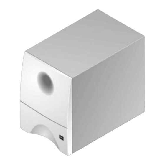
Single 5.25" powered multimedia subwoofer
Hide thumbs
Also See for Media Sub:
- Tehnical manual (16 pages) ,
- Owner's manual (9 pages) ,
- Brochure (4 pages)

Related Manuals for JBL Media Sub


Summary of Contents for JBL Media Sub
- Page 1 Media Sub Single 5.25" Powered Multimedia Subwoofer TECHNICAL MANUAL JBL Consumer Products Inc. 80 Crossways Park West Woodbury, N.Y. 11797 1-800-336-4JBL in the USA A Harman International Company Part No.: MEDIASUBSM Rev A...
-
Page 2: Table Of Contents
TABLE OF CONTENTS FEATURES..............1 PCB 3 (viewing trace layer through the board) ....7 SPECIFICATIONS............1 PCB 3 (viewing silk-screen through the board) ....8 MEDIA SUB EXPLODED VIEW ........2 ELECTRICAL PARTS LIST ...........9 DISASSEMBLY PROCEDURES ........3 PACKAGING EXPLODED VIEW.........10 BLOCK DIAGRAM ............4 INTEGRATED CIRCUIT DIAGRAMS ......11... -
Page 3: Media Sub Exploded View
Powered Subwoofer Media Sub MEDIA SUB EXPLODED VIEW... -
Page 4: Disassembly Procedures
Powered Subwoofer Media Sub DISASSEMBLY PROCEDURES Step 1 Remove the 8 purchase screws (S6) from the rear plate to separate the rear plate and the wood cabinet. Step 2 Unplug the connector speaker wire from the PCB amp assembly. Step 3 Remove the 4 purchase screws (S5) from the rear plate to separate the rear plate and cover. -
Page 5: Block Diagram
Powered Subwoofer Media Sub BLOCK DIAGRAM... -
Page 6: Pcb 1 & 2 (Viewing Trace Layer Through The Board)
Powered Subwoofer Media Sub PRINTED CIRCUIT BOARDS 1 & 2 (viewing trace layer through the board) -
Page 7: Pcb 1 & 2 (Viewing Silk-Screen Through The Board)
Powered Subwoofer Media Sub PRINTED CIRCUIT BOARDS 1 & 2 (viewing silk-screen through the board) -
Page 8: Pcb 3 (Viewing Trace Layer Through The Board)
Powered Subwoofer Media Sub PRINTED CIRCUIT BOARD 3 (viewing trace layer through the board) -
Page 9: Pcb 3 (Viewing Silk-Screen Through The Board)
Powered Subwoofer Media Sub PRINTED CIRCUIT BOARD 3 (viewing silk-screen through the board) -
Page 10: Electrical Parts List
Powered Subwoofer Media Sub ELECTRICAL PARTS LIST 820K Ω 1/6W ±5% REF. NO. PART NO. DESCRIPTION R121 QAF0650-824 10K Ω 1/6W ±5% R122, 123 QAF0650-103 Capacitors 1K Ω 1/6W ±5% R124 QAF0650-102 1.5K Ω 1/6W ±5% C101 PRE3955-479 ELECT 4.7 uF 50V 20%... -
Page 11: Packaging Exploded View
Powered Subwoofer Media Sub PACKAGING EXPLODED VIEW... -
Page 12: Integrated Circuit Diagrams
Powered Subwoofer Media Sub INTEGRATED CIRCUIT DIAGRAMS... - Page 13 POWERED SUBWOOFER Media Sub Media Sub Schematic Diagram Test voltages are printed in orange. Operational Mode voltages are displayed in boxes. Other voltages shown are for Stand-by Mode to the Auto On/Off function. +22.2V +22.4V IC103 0.0V 5.6V 5.6V STK4024 II 5.6V...
- Page 14 POWERED SUBWOOFER Media Sub Schemati 0.0V 5.6V 5.6V 5.6V 0.0V 5.6V 5.6V 5.61V 5.6V 5.6V 5.6V 5.6V 5.6V 5.6V 5.6V 5.6V 5.6V 5.6V 5.6V 5.6V 5.6V 5.6V 6.3V 7.25V 12.1V 4.8V 5.9V 1.36V 6.10V +11.0V 1.3V 2.47V 0.47V 2.48V 7.14V...
-
Page 15: Schematic Diagram
Media Sub b Schematic Diagram Test voltages are printed in orange. Operational Mode voltages are displayed in boxes. Other voltages shown are for Stand-by Mode to the Auto On/Off function. +22.2V +22.4V IC103 STK4024 II 0.0V 0.0V 0.0V 0.0V 0.0V 0.0V...
Need help?
Do you have a question about the Media Sub and is the answer not in the manual?
Questions and answers