Mitsubishi MLZ-KA25VA Service Manual
Indoor unit
outdoor unit service manual
mxz-a va series (ob377);
mxz-b va series (obh554);
mxz-8b va series (och480);
mxz-d va series (obh626)
Hide thumbs
Also See for MLZ-KA25VA:
- Installation manual (11 pages) ,
- Operating instructions manual (17 pages)
Advertisement
Table of Contents
- 1 Table of Contents
- 2 Technical Changes
- 3 Part Names and Functions
- 4 Specification
- 5 Noise Criteria Curves
- 6 Outlines and Dimensions
- 7 Wiring Diagram
- 8 Refrigerant System Diagram
- 9 Service Functions
- 10 Microprocessor Control
- 11 Disassembly Instructions
- Download this manual
See also:
Installation Manual
INDOOR UNIT
SERVICE MANUAL
Models
MLZ-KA25VA
MLZ-KA25VA
MLZ-KA35VA
MLZ-KA35VA
MLZ-KA50VA
MLZ-KA50VA
NOTE:
RoHS compliant products have <G> mark on the spec name plate.
-
E1
E2
E3
E4
,
,
,
-
ER3
ER4
,
-
E1
E2
E3
E4
,
,
,
-
ER3
ER4
,
-
E1
E2
E3
E4
,
,
,
-
ER3
ER4
,
CONTENTS
1. TECHNICAL CHANGES ···································
2. PART NAMES AND FUNCTIONS ····················· 3
3. SPECIFICATION ················································
MLZ-KA25VA
4. NOISE CRITERIA CURVES ······························
MLZ-KA35VA
5. OUTLINES AND DIMENSIONS ························
MLZ-KA50VA
6. WIRING DIAGRAM ············································
7. REFRIGERANT SYSTEM DIAGRAM ·············· 11
8. SERVICE FUNCTIONS ···································
9. MICROPROCESSOR CONTROL ··················· 15
11. DISASSEMBLY INSTRUCTIONS ···················· 36
PARTS CATALOG (OBB483)
Revision D:
• MLZ-KA25/35/50VA-
E4
added.
Please void OBH483 REVISED EDITION-C.
No. OBH483
REVISED EDITION-D
Outdoor unit service manual
MXZ-A VA Series (OB377)
MXZ-B VA Series (OBH554)
MXZ-8B VA Series (OCH480)
MXZ-D VA Series (OBH626)
,
have been
ER4
2
4
5
6
7
12
21
Advertisement
Table of Contents
Troubleshooting

Subscribe to Our Youtube Channel
Related Manuals for Mitsubishi MLZ-KA25VA


Summary of Contents for Mitsubishi MLZ-KA25VA
-
Page 1: Table Of Contents
• MLZ-KA25/35/50VA- have been added. Please void OBH483 REVISED EDITION-C. INDOOR UNIT No. OBH483 SERVICE MANUAL REVISED EDITION-D Models MLZ-KA25VA MLZ-KA25VA MLZ-KA35VA MLZ-KA35VA MLZ-KA50VA MLZ-KA50VA Outdoor unit service manual MXZ-A VA Series (OB377) MXZ-B VA Series (OBH554) MXZ-8B VA Series (OCH480) -
Page 2: Technical Changes
Revision B : • MLZ-KA25/35/50VA- have been added. Revision C : • MLZ-KA25/35/50VA- have been added. Revision D : • MLZ-KA25/35/50VA- have been added. TECHNICAL CHANGES MLZ-KA25VA- MLZ-KA35VA- MLZ-KA50VA- 1. New model MLZ-KA25VA- MLZ-KA25VA- MLZ-KA35VA- MLZ-KA35VA- MLZ-KA50VA- MLZ-KA50VA- 1. Fan motor has been changed (RC0J30-KC RC0J30-KK). -
Page 3: Part Names And Functions
PART NAMES AND FUNCTIONS INDOOR UNIT MLZ-KA25VA MLZ-KA35VA MLZ-KA50VA MLZ-KA25/35/50VA- Horizontal vane Air inlet Air outlet Vertical vane Intake grille Air filter (Catechin air filter, option) Air cleaning filter (Anti-Allergy Enzyme Filter, option) Display and operation section (When the intake grille is opened) -
Page 4: Specification
Dry-bulb temperature 20°C Outdoor Dry-bulb temperature 7°C Wet-bulb temperature 6°C Refrigerant piping length (one way): 5m 1 Measured under rated operating frequency. Specifications and rated conditions of main electric parts Model MLZ-KA25VA MLZ-KA35VA MLZ-KA50VA Item Fuse (F11) T3.15AL 250V Horizontal vane motor (MV1) 12V 300Ω... -
Page 5: Noise Criteria Curves
NOISE CRITERIA CURVES MLZ-KA25VA MLZ-KA35VA FAN SPEED FUNCTION SPL(dB(A)) LINE FAN SPEED FUNCTION SPL(dB(A)) LINE COOLING COOLING High High HEATING HEATING Test conditions, Test conditions, Cooling: Dry-bulb temperature 27ºC Wet-bulb temperature 19ºC Cooling: Dry-bulb temperature 27ºC Wet-bulb temperature 19ºC Heating: Dry-bulb temperature 20ºC Heating: Dry-bulb temperature 20ºC... -
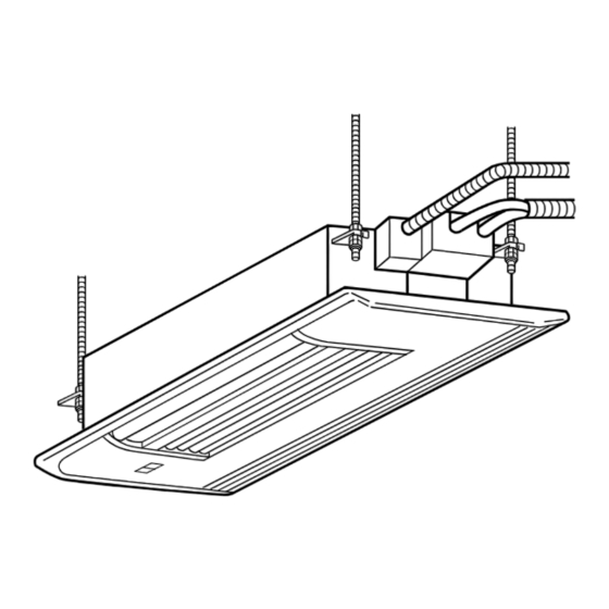
Page 6: Outlines And Dimensions
OUTLINES AND DIMENSIONS MLZ-KA25VA MLZ-KA35VA MLZ-KA50VA Unit : mm INDOOR UNIT Center of ceiling opening, suspension bolt pitch (Top) Wireless and grille are located in one position. remote controller Drain hose Air outlet Electrical connecting part Gas pipe 1051 Suspension bolt pitch MLZ-KA25/35: Ø9.52... -
Page 7: Wiring Diagram
WIRING DIAGRAM INDOOR UNIT MLZ-KA25VA- MLZ-KA35VA- MLZ-KA25VA- MLZ-KA35VA- OBH483D... - Page 8 MLZ-KA25VA- MLZ-KA35VA- MLZ-KA25VA- MLZ-KA35VA- OBH483D...
- Page 9 MLZ-KA50VA- MLZ-KA50VA- OBH483D...
- Page 10 MLZ-KA50VA- MLZ-KA50VA- OBH483D...
-
Page 11: Refrigerant System Diagram
REFRIGERANT SYSTEM DIAGRAM INDOOR UNIT MLZ-KA25VA MLZ-KA50VA Unit : mm MLZ-KA35VA Refrigerant pipe Ø9.52 Refrigerant pipe Ø12.7 (with heat insulator) (with heat insulator) Indoor coil Indoor coil thermistor thermistor Indoor Indoor RT12,RT14, heat heat RT12 (main) RT15 (main) exchanger Flared connection... -
Page 12: Service Functions
SERVICE FUNCTIONS MLZ-KA25VA MLZ-KA35VA MLZ-KA50VA 8-1. TIMER SHORT MODE • For service, the following set time can be shortened by bridging the JPG and JPS (MLZ-KA·VA- timer short mode point (MLZ-KA·VA- ) on the electronic control P.C. board. (Refer to 10-7.) •... - Page 13 8-3. AUTO RESTART FUNCTION When the indoor unit is controlled with the remote controller, the operation mode, the set temperature, and the fan speed are memorized by the indoor electronic control P.C. board. “AUTO RESTART FUNCTION” automatically starts operation in the same mode just before the shutoff of the main power. Operation If the main power has been cut, the operation settings remain.
- Page 14 8-4. P.C. BOARD MODIFICATION FOR CHANGING AIRFLOW VOLUME Change dip switch SW3 setting according to the height of ceiling. Dip switch SW3 Normal Increase airflow volume Ceiling height 2.4 m or below above 2.4 m and 2.7 m or below NOTE: When the ceiling is above 2.7 m, airflow volume may be insufficient even with the Dip switch (SW3) set to "increase airflow".
-
Page 15: Microprocessor Control
MICROPROCESSOR CONTROL MLZ-KA25VA MLZ-KA35VA MLZ-KA50VA· WIRELESS REMOTE CONTROLLER MLZ-KA25/35/50VA- Signal transmitting section Operation display section OPERATE/STOP (ON/OFF) button Temperature buttons Indication of Open the front lid. remote controller model is on back WIDE VANE button FAN SPEED CONTROL button OFF-TIMER button... - Page 16 MLZ-KA25/35/50VA- Signal transmitting section Operation display section STOP/OPERATE (OFF/ON) button Temperature buttons Indication of Open the front lid. remote controller model is on back WIDE VANE button FAN SPEED CONTROL button OFF-TIMER button OPERATION SELECT button ECONO COOL button ON-TIMER button TIME SET buttons FORWARD button BACKWARD button...
- Page 17 INDOOR UNIT DISPLAY SECTION Operation Indicator lamp The operation indicator at the left side of the indoor unit indicates the operation state. Difference between target temperature and Indication Operation state room temperature This shows that the air conditioner is Lighted Approximate operating to reach the target temperature.
- Page 18 9-5. AUTO VANE OPERATION 1. Horizontal vane (1) Vane motor drive These models are equipped with a stepping motor for the horizontal vane. The rotating direction, speed, and angle of the motor are controlled by pulse signals (approximately 12V) transmitted from indoor microprocessor. (2) The horizontal vane angle and mode change as follows by pressing VANE CONTROL button.
- Page 19 2. Vertical vane (1) Press WIDE VANE button to change horizontal airflow direction. •The vertical vane moves for about 30 seconds. (After 30 seconds, the vertical vane moves to its original position. In this case, press WIDE VANE button again.) (2) Press WIDE VANE button again to set horizontal airflow direction.
- Page 20 2. Cancel To cancel ON timer, press ON-TIMER button ( To cancel OFF timer, press OFF-TIMER button ( TIMER is cancelled and the display of set time disappears. PROGRAM TIMER • OFF timer and ON timer can be used in combination. The time that is reached first will operate first. •...
-
Page 21: Troubleshooting
TROUBLESHOOTING MLZ-KA25VA MLZ-KA35VA MLZ-KA50VA 10-1. CAUTIONS ON TROUBLESHOOTING 1. Before troubleshooting, check the following: 1) Check the power supply voltage. 2) Check the indoor/outdoor connecting wire for miswiring. 2. Take care of the following during servicing 1) Before servicing the air conditioner, be sure to turn off the unit first with the remote controller, and then after confirming the horizontal vane is closed, turn off the breaker and/or disconnect the power plug. - Page 22 10-2. FAILURE MODE RECALL FUNCTION Outline of the function This air conditioner can memorize the abnormal condition which has occurred once. Even though OPERATION INDICATOR lamp indication listed on the troubleshooting check table (10-4.) disappears, the memorized failure details can be recalled. This mode is very useful when the unit needs to be repaired for the abnormality which does not recur.
- Page 23 2. Flow chart of the detailed outdoor unit failure mode recall function Operational procedure The outdoor unit might be abnormal. Check if outdoor unit is abnormal according to the following procedures. Make sure that the remote controller is set to the failure mode recall function.
- Page 24 3. Indoor unit failure mode table NOTE: Blinking patterns of this mode differs from the ones of Troubleshooting check table (10-4.). Left lamp of Right lamp of Abnormal point Condition Remedy OPERATION OPERATION (Failure mode) INDICATOR lamp INDICATOR lamp Not lighted Not lighted Normal –...
- Page 25 10-3. INSTRUCTION OF TROUBLESHOOTING Start Indoor unit Indoor unit Indoor unit operates. OPERATION INDICATOR operates. does not receive Outdoor unit does not lamp on the indoor unit is Outdoor unit the signal from operate normally. flashing on and off. does not remote controller.
- Page 26 10-4. TROUBLESHOOTING CHECK TABLE OPERATION INDICATOR · Flashing of OPERATION INDICATOR lamp (left-hand side lamp) indicates Lighted abnormalities. Blinking Not lighted NOTE: Before taking measures, make sure that the symptom reappears for accurate troubleshooting. Self check table Abnormal Operation indicator lamp Symptom Condition Remedy...
- Page 27 NOTE: When the indoor unit has started operation and the above failures are detected (the first detection after the power ON), the indoor electronic control P.C. board turns OFF the indoor fan motor with OPERATION INDICATOR lamp flashing. 10-5. TROUBLE JUDGEMENT CRITERIA OF MAIN PARTS MLZ-KA25VA MLZ-KA35VA MLZ-KA50VA Part name Check method and criteria...
-
Page 28: Troubleshooting Flow
10-6. TROUBLESHOOTING FLOW When the left lamp of OPERATION INDICATOR lamp flashes 3 times and the right lamp of OPERATION INDICATOR lamp is not lighted. Indoor fan does not operate. Check of indoor fan motor The indoor fan motor error has occurred, and the indoor fan does not operate. Turn OFF the power supply. - Page 29 Indoor unit operates by pressing EMERGENCY OPERATION switch, but does not operate with the remote controller. Check of remote controller, display receiver P.C. board and indoor control P.C. board Check if the remote controller is exclusive for this air conditioner. Press STOP/OPERATE (OFF/ON) (MLZ-KA·VA- OPERATE/STOP (ON/OFF) (MLZ-KA·VA- button on the remote controller.
- Page 30 The unit cannot be operated with the remote controller. Also, OPERATION INDICATOR lamp does not light up by pressing EMERGENCY OPERATION switch. Check of indoor electronic control P.C. board and indoor fan motor Turn OFF the power supply. Remove indoor fan motor connector CN211 and vane Turn OFF the power supply.
- Page 31 When the left lamp of OPERATION INDICATOR lamp flashes ON and OFF in every 0.5-second. Outdoor unit does not operate. How to check miswiring and serial signal error Turn OFF the power supply. Is there rated voltage of Check the power 230 VAC in the power supply.
- Page 32 When the left lamp of OPERATION INDICATOR lamp flashes 9-time. Indoor unit and outdoor unit do not operate. Check of float sensor Turn OFF the power supply and check connectors CN145 and CN1N1 visually. Are there abnormality in Are the lead wires the soldering part of Solder the connector.
- Page 33 Electromagnetic noise enters into TV sets or radios Is the unit earthed? Earth the unit. Is the distance between the Extend the distance between antennas and the indoor the antennas and the indoor unit within 3m, or is the unit, or the antennas distance between the and the outdoor unit.
- Page 34 10-7. TEST POINT DIAGRAM AND VOLTAGE MLZ-KA25VA- MLZ-KA35VA- MLZ-KA50VA- Indoor electronic control P.C. board NR11 CN1N1 CN145 CN202 Varistor Drain pump Float sensor Serial signal F11 FUSE R111 T3.15AL250V CN201 Power supply input 230 VAC Modif ca- tion JR05 point for...
- Page 35 MLZ-KA25VA- MLZ-KA35VA- MLZ-KA50VA- Indoor electronic control P.C. board NR11 CN145 CN202 CN1N1 Float Varistor R111 Serial signal Drain pump sensor F11 FUSE T3.15AL250V CN201 Power supply input 230 VAC CN111 Room temperature thermistor RT11 CN112 Indoor coil ther- mistor RT14...
-
Page 36: Disassembly Instructions
Locking lever lever. Connector MLZ-KA25VA MLZ-KA35VA MLZ-KA50VA NOTE: Turn OFF the power supply before disassembly. OPERATING PROCEDURE PHOTOS 1. Opening the intake grille Photo 1 (1) Press the area indicated “PUSH” on the intake grille until a Places for installing the Anti-Allergy Enzyme click is heard (Figure 1). - Page 37 OPERATING PROCEDURE PHOTOS 3. Checks before setting in place Figure 4 Close-up (1) Before installing the grille, make sure the indoor unit is square with the ceiling opening (or parallel to the wall-ceiling joint). Points for securing the grille (2) Check that the four points for securing the grille are in con- tact with the ceiling surface.
- Page 38 OPERATING PROCEDURE PHOTOS Figure 9 7. Check after installing Indoor unit (1) Check that there are no gaps between the indoor unit and grille, and between the grille and ceiling surface (Figure 9). (If there are gaps, the wind may come in and dew conden- sation may result.) (2) Is the air filter installed? Ceiling surface...
- Page 39 OPERATING PROCEDURE PHOTOS 11. Removing the drain pump and float sensor Photo 4 (1) Remove the grille. Horizontal vane motor (2) Remove the drain pan. Vertical vane motor (3) Disconnect the connector of the drain pump (Photo 5). (4) Disconnect the connector of the float sensor (Photo 5). (5) Remove the drain hose (Photo 5).
- Page 40 HEAD OFFICE: TOKYO BLDG., 2-7-3, MARUNOUCHI, CHIYODA-KU, TOKYO 100-8310, JAPAN © Copyright 2012 MITSUBISHI ELECTRIC CORPORATION Distributed in Dec. 2015 No. OBH483 REVISED EDITION-D Distributed in Jan. 2014 No. OBH483 REVISED EDITION-C Distributed in Nov. 2012 No. OBH483 REVISED EDITION-B Distributed in Nov.
Need help?
Do you have a question about the MLZ-KA25VA and is the answer not in the manual?
Questions and answers