Table of Contents
Advertisement
Quick Links
Advertisement
Table of Contents

Related Manuals for Pure Humidifier ER Series


Summary of Contents for Pure Humidifier ER Series
- Page 1 READ AND SAVE THESE INSTRUCTIONS Standard Water “ER” Series Electric Humidifier Installation Instructions ————————————————— Operation and Maintenance Manual Our results are comforting ® ® PURE HUMIDIFIER and INTAC are registered trademarks of PURE Humidifier Co. Form No: EROM-4-16...
-
Page 2: Table Of Contents
To the user of PURE Humidifier Co.’s Electric Table of Contents Humidifiers Introduction We at PURE Humidifier Co. thank you for choosing one of Capacity & Weights our quality products. PURE Humidifier Co. Electric Series Electrical Specifications Humidifiers are models of simplicity to install, operate, and Dimensions &... -
Page 3: Capacity & Weights
Capacity & Weights Electrical Specifications Capacities & Weights Humidifier Reservoir Weight Standard Steam Output Capacity † Empty Full Water Unit Model No. lbs/hr kg/hr ER-1 31.4 ER-3 31.4 ER-5 31.4 ER-6 31.4 ER-7 31.4 † The above capacities are based on 100% efficiency. Actual humidifier capacity may vary due to the heat loss from the humidifier reservoir. -
Page 4: Dimensions & Layout
Dimensions & Layout 1 1/2”Ø Steam Outlet Connection 11.00” (27.9) 15.375” (39.0) Top View Electrical Control Box 1/4”-NPT Water Inlet & 7.375” Strainer (18.7) 16.75” (42.5) 9.375” 3/4” Copper Sweat Drain Drain Valve (23.8) Connection 12.375” (31.4) 14.625” (37.1) Front View Right Side View... -
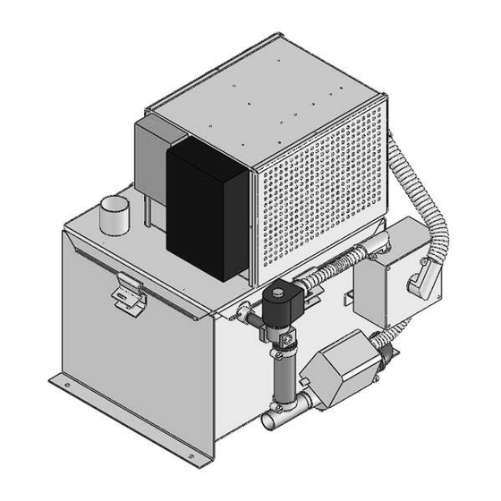
Page 5: Humidifier Layout
Humidifier Layout Controls Cover Optional SCR Control Optional Time Cycle Modulation Control Water Level Controller Tri-Probe Sensor Reservoir Cover Immersion Heaters Humidifier Reservoir 1/4” IPS Water Inlet and Strainer Motorized Drain Valve Drain & Overflow Outlet... -
Page 6: Location
Location of Controls Fan Interlock Switch PURE Humidifier Co. recommends the use of an air flow proving switch or fan interlock to prove air flow prior to humidifier cooperation. Humidifier operation without air flow will result in over-saturation of the air stream. Air... -
Page 7: Drain Pan Mounting
However, if the humidifier and injection tube are located in an area that contains valuable equipment or is a water sensitive area, PURE Humidifier Co. recommends the addition of a drain pan under the humidifier and under the injection tube. The drain pan should extend past all edges of the humidifier and if installed in the duct, it should extend a minimum of 3 feet (91 cm) downstream from the injection tube. -
Page 8: Flexible Hose Kit Installation
3/4” SW Condensate drain line (by others) The hose connects to the injection tube and humidifier with stainless steel hose clamps (by PURE Humidifier Co.). Open Sanitary ∆ Minimum water seal of 2” plus duct Galvanized steel duct plates are provided to static pressure. -
Page 9: Piping
Cold or hot standard tap water can be supplied to condensate pump rated for 212°F water or contact a the humidifier. A minimum water pressure of 35 psi PURE Humidifier Co. representative to purchase (2.4 Bar) should be maintained to provide the one. -
Page 10: Blower Pack
Blower Pack Optional Blower Pack Locating Blower Pack In applications where a ducted air system is not The distance that visible steam will travel after available, PURE offers the optional Blower Pack. leaving the Blower Pack is dependent upon the Blower Pack contains... -
Page 11: Blower Pack
Blower Pack Locating Blower Pack The distance that visible steam will travel after leaving the Blower Pack is dependent upon the relative humidity in the room and the capacity of the humidifier. If this visible steam comes in contact with any solid object (walls, beams, machinery, etc.) it may form condensate and drip. -
Page 12: Pre-Startup Checklist
Pre-Startup Checklist Pre-Startup Checklist Before starting the “ER” PURE Humidifier Co. Electric Humidifier, check the following installation items: ______ 1. MOUNTING - Verify that the humidifier evaporating chamber is securely supported and that the evaporating chamber is level in both directions. If humidifier is installed above equipment or not located near a floor drain then a drain pan should be installed below the humidifier steam generator. -
Page 13: Non-Intac Start-Up Procedure
® Non-INTAC Start-Up Procedure Start Up Procedure ______ 1. With the power "off", set the switch on the LC-942 level controller to the "Stand-by" position. ______ 2. Make sure the manual drain valve lever (located on the side of the drain valve) is in the “automatic” position. -
Page 14: Intac ® Start-Up Procedure
® INTAC Start-Up Procedure Start Up Procedure ______ 1. Make sure the manual drain valve lever (located on the front of the drain valve) is in the “automatic” position. ® ______ 2. Turn the electric power “on” to the humidifier. The LCD display on the INTAC controller should illuminate “Normal Operation”... -
Page 15: Maintenance & Cleaning Instructions
However, the humidifier should be inspected and place on a dedicated maintenance schedule to ensure continued operation of the humidifier and its accessories. PURE Humidifier Co. recommends that the following items be inspected and/or cleaned on a minimum basis of twice a year. -
Page 16: Cover Gasket Replacement Instructions
Cover Gasket Replacement Instructions Installation Remove cover. Fit the gasket around the entire lip of the tank opening. Cut the gasket 1/8” longer than required, this will ensure proper fit when the cover is clamped back on. Slide the gasket onto lip of tank around the entire perimeter, and seal the ends together with a small amount of silicone. -
Page 17: Troubleshooting
Troubleshooting Recommended Action Problem Possible Cause Check and replace. Blown heater fuse(s) Humidifier will not heat Check transformer output. Control transformer not Verify voltage across terminals #9 (hot) and #10 producing 24 vac control (comm). voltage Verify that all safety controls are completing the Safety controls open safety circuit. -
Page 18: Tool Requirements & Torque List
Tool Requirements & Torgue List Recommended Maintenance Tool List 7/16” Wrench 5/16” Nut Driver or Socket 11/32” Nut Driver or Socket 5/32” Nut Driver or Socket Pliers Flat head screwdriver Wire stripper Wire crimper Torque List Cover Bolts 18 inch/pounds MAX Hose Cuff Screws 35-40 inch/pounds MAX when hot Heater Nut... -
Page 19: Maintenance Notes
Maintenance Notes Maintenance Notes Maintenance Performed Date... -
Page 21: Parts List
PURE Humididfier Co. "ER" Series Parts List & Two Year Recommended Spare Parts Item No. Description Part No. Rec. Per Unit SpareQty ER Reservior Assembly 97043 ER Reservior Cover Assembly 97041 Cover Gasket 15520 Immersion Heating Element(s) Cover Clamp 15930 Cover Clamp Screws 15522 10-24 U-Nut... - Page 22 ...
- Page 23 ...
- Page 24 141 Jonathan Blvd. North Chaska, MN 55318 Tel: (952) 368-9335 Fax: (952) 368-9338 www.purehumidifier.com...
Need help?
Do you have a question about the ER Series and is the answer not in the manual?
Questions and answers