
Subscribe to Our Youtube Channel
Related Manuals for HYCON HCD25-100

Summary of Contents for HYCON HCD25-100
- Page 1 Hydraulic Core Drill HCD25-100 • HCD50-200 HYCON A/S Juelstrupparken 11 DK-9530 Støvring Denmark Tel: +45 9647 5200 Fax: +45 9647 5201 Mail: hycon@hycon.dk www.hycon.dk...
-
Page 2: Table Of Contents
Contents Page Safety Precautions ..................2 Oil Flow, Pressure and Testing ..............4 Technical Data .................... 5 Dimensions ....................6 Service and Maintenance ................7 Fault Location ..................... 8 Dismounting and Mounting of Main Components .......... 9 Repair of Bearing Housing ................19 Repair of Valve Housing ................ -
Page 3: Safety Precautions
• Make sure that the core bit is firmly fastened. • For handheld drilling, always use core bits approved for this purpose. • The HYCON core drill is supplied with a trigger lock. This may only be used when drilling in a rig. - Page 4 • A core drill not in use should always be kept in a safe and dry place. • Always make sure that the core drill labels and warning signs are legible. • Always use hoses, couplings and spares as such recommend by HYCON A/S. • Repairs may only be carried out by experienced personnel.
-
Page 5: Oil Flow, Pressure And Testing
A too high oil flow and/or a too high pressure results in overload of the core drill, meaning that the lifetime of your new HYCON tool will not be as expected, and that your service and repair costs will be too high. -
Page 6: Technical Data
3. Technical Data HCD25-100 HCD50-200 Weight w/o hoses, core bit and adaptor 7.6 kg 7.6 kg Oil flow 20 l.p.m. 20 l.p.m. Working pressure nominal 100 bar 100 bar Pressure relief valve in power source Max. 170 bar Max. 170 bar Max. -
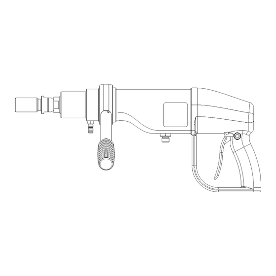
Page 7: Dimensions
4. Dimensions... -
Page 8: Service And Maintenance
Check bearing for clearance NB. At service/repair it is important to mount the hoses correctly. Oil Types The HYCON core drill uses standard hydraulic oil, i.e. all types of mineral oil and biodegradable oil, which comply with the following values: Recommended viscosity... -
Page 9: Fault Location
6. Fault Location Before you start locating faults, check that the oil flow from the power source is correct, and that the pressure relief valve is set correctly. Follow the instructions in the workshop manual of the power source. Problem Cause Solution Core drill does not start,... -
Page 10: Dismounting And Mounting Of Main Components
7. Dismounting and Mounting of Main Components Dismount the front adaptor and the water hose. Dismount the handle ring for the supporting handle, and remove supporting handle. Mount HYCON service tool No. 1 (special screw) and No. 2 (tightening cup). The bearing housing can now be removed from the motor adaptor. - Page 11 Loosen the three screws, and remove the motor adaptor. Dismount the two screws at the back of the handle, and remove the handle. Dismount the distance piece. Then dismount the tail-hoses. Wait a while to let the hydraulic oil run out. The valve block with motor can now be pulled out of the plastic cover.
- Page 12 Dismount the two banjo bolts, and remove the valve block from the motor. Core Drill Main Components...
- Page 13 Mounting Place the two O-rings on the motor, and mount the valve housing over the motor. It is important that the O-rings are placed precisely in the grooves on motor and valve block. Mount the seal rings on the banjo bolts, and mount the banjo bolts through the valve block into the motor.
- Page 14 Mount the pressure relief valve, and tighten with a torque of 30 Nm. Mount the trigger piston, and add Loctite 243 to the two threads. Mount the mounting plate and the two screws. Tighten the screws with a torque of 30 Nm. Mount the four cylinder pins.
- Page 15 Push motor and valve block into the plastic cover. Mount the two fittings and tighten with a torque of 70 Nm. Mount the tail-hoses. Mount the hose with male coupling at ”T”, and the hose with female coupling at ”P”. Clean the three threads on the motor with Loctite 7063, and add Loctite 243 to the threads.
- Page 16 Hold on to the core drill so that it does not revolve, and read the pressure on the pressure gauge. Normal setting is 115 bar for the HCD50-200 and 125 bar for the HCD25-100. If the pressure deviates too much, adjust the set screw a little in or out.
- Page 17 Mounting of Handle Place the trigger lever in the handle, and mount the pin through all three holes. Mount a retaining ring on each side. Mount the trigger lock on the handle.
- Page 18 Add Loctite 243 to the two threads, and mount the handle on the valve block. Always mount the distance piece between trigger rod and handle (check distance piece for wear. Replace it, if too worn). Tighten the two screws with a torque of 25 Nm. Mount the handle ring for the supporting handle.
- Page 19 Mount the supporting handle. Grease the thread on the front adaptor with copper paste, and mount it on the shaft.
-
Page 20: Repair Of Bearing Housing
Use a drift punch and a hammer to remove the shaft from the bearing housing. Then use HYCON service tool No. 3 to remove the bearing and the seal housing at the other end of the bearing housing. Replace all seals and O-rings on... - Page 21 Carefully grease seal housing and bearing housing on the inside. Place the seal housing in the bearing housing. Hammer in the seal housing by means of HYCON service tools No. 3 and 4 (top and bottom). By using these special tools, the seal...
- Page 22 Turn the bearing housing and grease on the inside of the bearing housing and on the bearing. Hammer in the bearing by means of the same HYCON service tools No. 3 and 4. Turn the bearing housing, grease bearing housing and bearing again.
- Page 23 Grease the shaft and mount it down through the bearings. Hammer in the shaft by means of HYCON service tools No. 4 and 5. Position the compression rings with the curves away from each other before mounting them on the shaft. Mount the distance...
- Page 24 Turn the bearing housing, and carefully mount the seal on the shaft. Use HYCON service tool No. 7 to fasten the seal. Check that the shaft can revolve.
-
Page 25: Repair Of Valve Housing
9. Repair of Valve Housing Dismounting Dismount the pressure relief valve. Then dismount the banjo bolts, and remove the valve housing from the motor. Dismount the two screws and remove the trigger mounting plate. Carefully remove the seal housing from the valve block with a pair of pliers. - Page 26 Mounting Add Loctite 542 to the four threads, and mount the pipe plugs. Screw the pipe plug 1/8” fully in (only applies to the HCD50-200 model). Add Loctite 542 to the upper part of the thread and mount the pipe plug 1/4”. Mount the threaded plug with seal on the valve block.
-
Page 27: Tool List
½” torque wrenches 5-50 Nm, 10-130 Nm h. Hammer d. ½” socket 24 mm long, ½” socket 27 mm long i. Drift punch e. Combination spanners, sizes 14, 17, 22, 24, 27 HYCON Service Tools Part No. 9992245 Puller...
Need help?
Do you have a question about the HCD25-100 and is the answer not in the manual?
Questions and answers