Table of Contents
Advertisement
Operating and
Maintenance Instructions
Important Note
These operating instructions
are designed to familiarize
the user with the machine
and its designated use.
The Instruction Manual
∙ Contains important information
on how to operate the machine
safely, properly and efficiently.
Observing these instructions
help to avoid danger to reduce
repair costs and downtimes and
to increase the reliability and life
of the machine.
∙ Must always be available
NETZSCH Pumps North America, LLC
119 Pickering Way ∙ Exton, PA 19341
610.363.8010 ∙ Fax 610.363.0971
Email: npa@netzsch.com
www.netzsch.com
wherever the machine is in use.
∙ Must be read and applied by
any person in charge of carrying
out work with and on the mach-
ine. Such as:
Operation including setting up,
troubleshooting in the course of
work, evacuation of production
waste, care and disposal of fuels
and consumables.
Maintenance (servicing, inspe-
ction, and/or repair)
NEMO
Model Number
Sales Order/Job Number
Machine Number
Date of Issue
NM BY
Transport; shall be completed by
the end user and authorized perso-
nnel with the national requirements
in force for the prevention of acci-
dents and the environmental protec-
tion.
In addition to the operating instruct-
ions and to the mandatoryrules and
regulations for accident prevention
and environmental protection in the
country and place of use of the mac-
hine, the generally recognized tech-
nical rules for safe and proper
working must be observed.
®
Pump
Advertisement
Table of Contents

Related Manuals for NETZSCH NEMO

Summary of Contents for NETZSCH NEMO
- Page 1 Maintenance (servicing, inspe- nical rules for safe and proper ction, and/or repair) working must be observed. ∙ Must always be available NETZSCH Pumps North America, LLC 119 Pickering Way ∙ Exton, PA 19341 610.363.8010 ∙ Fax 610.363.0971 Email: npa@netzsch.com www.netzsch.com...
- Page 2 MUST How the pump works NETZSCH Progressing Cavity Pumps operate at a constant torque requirement for a specific operating pressure. The speed of the pump does NOT affect the torque requirement. For example: a pump running at 60psi output pressure at a speed of 200 revolutions per minute requires the same toque input as if it were running at 60psi output pressure at a speed of 600 revolutions per minute.
- Page 3 NETZSCH Pumps North America, LLC has an overload capacity of the VFD's full load ampere rating times 110% - 120% for one minute and Heavy Duty; which has an overload capacity of the VFD's full load ampere rating times 150% for one minute. Typically, constant Hp VFD’s are sold with a Normal duty rating since the applications don’t call for high starting torque which causes amp draw to spike.
-
Page 4: Table Of Contents
PAGE TABLE OF CONTENTS Page 1 Safety Precautions 2 Description 3 Packing, Transportation, Storage 4 Installation Instructions 5 Start-up 6 Temporary Shutdown 7 Maintenance 8 Trouble-Shooting and Remedying 9 Dismantling and Assembly of the Pump Housing 10 Dismantling and Assembly of the Rotating Parts 10.0 11 Removal and Fitting of the Connecting Shaft 11.0... -
Page 5: Safety Precautions
PAGE 1 SAFETY PRECAUTIONS 1 Safety Instructions This manual contains basic instructions which necessary to observe the special safety rules must be observed when installing, operating included in other sections of the manual, eg. and servicing the machine / equipment. It is for private use. - Page 6 PAGE 1 SAFETY PRECAUTIONS 1.0R Warning plates located directly on the pump/ – setting up installations into a plant must be equipment showing for example the correct qualified / trained as an industrial mechanic/ direction of rotation or the fluid connections technician and must be familiar with the used must always be observed and kept com- design and functioning of the plant in which...
- Page 7 PAGE 1 SAFETY PRECAUTIONS Danger to personnel from electricity, All possible danger from electricity must machinery and chemicals be eliminated (for details see eg. the regulations of your local power supply Danger to the environment from company). leakage of hazardous substances. 1.6 Safety Instructions for Maintenance, Inspection 1.4 Safety Conscious Working...
- Page 8 1. Ensure that the pump drive can not NEMO ® Pump be turned on without authorization. A NEMO ® pump must be used for the 2. When opening the pump follow purpose only for which it was sold. the instructions for handling the medium (eg.
- Page 9 1 SAFETY PRECAUTIONS Always bear in mind your safety during operation, maintenance and installation of equipment. Please adhere to the EC- Directive for machinery including the national regulations and follow the US OSHA regulation #1910.219 & 1910.147 titled Mechanical Power transmission apparatus as well as the European Standard EN 292 with the accidents prevention rules laid down by the trade...
- Page 10 PAGE 1 SAFETY PRECAUTIONS Always bear in mind your safety during operation, maintenance and installation of equipment. Please adhere to the EC-Directive for Machinery including the national regulations and follow the European Standard EN 292 with the accident prevention rules laid down by the trade unions and other appropriate technical institutions.
- Page 11 PAGE 1 SAFETY PRECAUTIONS 1.2R 1.10 Notes on Inspection and Repair authorized and qualified specialist. Please use a copy and leave the original in the operati- The legal regulations for safety at work, on and maintenance manual. such as regulations for the workplace, regu- lations governing dangerous materials, acci- Where special safety precautions are neces- dent prevention, environmental protection...
- Page 12 PAGE 1 SAFETY PRECAUTIONS 1.11 Instructions concerning explosion protection The instructions below are to be considered and kept to when using pumps in potentially explosive areas in order to guarantee durable explosion protection of the pumps and avoid any danger of ignition. In accordance with the regulations 94 / 9 / EC, the pumps are admitted for use in the area II 2G IIB T 4 or II 2G IIB T 3 (pls.
- Page 13 PAGE 1 SAFETY PRECAUTIONS 1.3R The device for dry-running protection should be self-regulating. This means that this device can give alarm signals and/or switch off the pump also in case of failures in its own control system. Dry-running protection concerning stationary immersion pumps (with mounting plate) Operation is only permitted with redundant or self-regulating automatic devices to guarantee dry-running protection as well as to control the pump...
- Page 14 PAGE 1 SAFETY PRECAUTIONS The connection to ground is to be maintained until the pump has been completely pulled out of the container. There must not be any potential difference between the pump and a conductive container. This means that container and pump are to be connected at a common grounding point and thus be conductively connected with each other.
- Page 15 PAGE 1 SAFETY PRECAUTIONS 1.4R 11. Shaft bearings (concerning the pump types SY / SH / SA / SO / SF / SP) Replacement of the bearings after 14,500 operating hours (according to prEN 13463-5: replacement after 90 % of the designated service life). 12.
- Page 16 PAGE 1 SAFETY PRECAUTIONS Safety Conformity Certificate The machinery and its accessories together with this safety conformity certificate relating to repair / inspection services given to the undersigned by ourselves Machine Type ........Number ........Delivery Date ........Delivery Note No........was carefully emptied and cleaned both inside and out in preparation for shipment Special safety precautions with regard to health or...
-
Page 17: Description
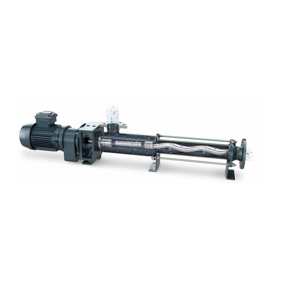
Like gear pumps and screw pumps the NEMO ® pump is capable of coping with high medium viscosities. Length and cross-sections through the rotor Like piston, membrane, gear or screw pumps the NEMO ®... - Page 18 PAGE 2 DESCRIPTION AND GENERAL DATA 2.0R 1/2-geometry 2/3-geometry Length and cross-sections through the stator with rotor with reduced stator wall thickness General Data Noise emissions: The maximum permitted noise emission level at a work place is 70 dB (A). The noise level was measured in accordance with DIN Standard 45635-24-01-KL2 to assure that the pump does not exceed 70 dB (A).
- Page 19 3 PACKAGING, TRANSPORTATION, STORAGE Packaging, Transportation, Storage 3.1 Packaging and Transportation NEMO ® pumps are shipped in railroad containers or crates unless the customer specifies otherwise. The packings are labelled and symbols give the handling instructions in accordance with DIN 55402.
- Page 20 PAGE 3 PACKAGING, TRANSPORTATION, STORAGE 3.0R When moving the pump or unit on wheels strictly attend to the following: Pad lock the motor drive and secure against unintended starting up. Move the pump unit carefully and slowly, especially where the ground is uneven.
- Page 21 PAGE 3 PACKAGING, TRANSPORTATION, STORAGE Store room The environment in which rubber products are being kept must be cool, dry, free of dust and rather airy, and they must not be stored in the open, not even in a weather sheltered space. Rubber products should be kept in surroundings not having less than minus 10 °C and not more than plus 15 °C.
-
Page 22: Installation Instructions
PAGE 4 INSTALLATION INSTRUCTIONS Mounting and Installation If the NEMO ® pump was stored and the rotor grease protected: Remove the grease before installing the stator. Clean the rotor thoroughly in order to avoid unsuitability of the grease with the stator material and the pumping medium. - Page 23 PAGE 4 INSTALLATION INSTRUCTIONS 4.0R The installation of a removable distance piece between the end flange (B) and the pipe work is recommended in order to make the dismantling of the stator easy. The distance piece (see sketch) needs to have a minimum "ABL"...
- Page 24 PAGE 4 INSTALLATION INSTRUCTIONS Type key Example: N M 0 9 0 B Y 0 2 S 1 2 B Internal Pump size Type Model Number of stages Geometry max. permissible pressure difference anti–clockwise Joint The disassembly length "ABL" is also shown in the arrangement drawings in accordance with our Standard QSH V - TB 01 - 002.
-
Page 25: Electrical Connection
PAGE 4 INSTALLATION INSTRUCTIONS 4.1R Pump Standard F x, F y, F z M x, M y, M z type nominal diameter " (32) (300) Screwed joints must not be charged with loads 1160 which may result in 1490 tightening or loosening 1820 these joints... -
Page 26: Start-Up
Fill the piping on the pump suction side. In anti–clockwise rotation only: Fill the pump housing. The NEMO ® pump is a progressing cavity pump which can produce pressures that may cause the bursting of vessels or pipes. The power transmission train (shaft, coupling rod, joints, rotor) of the pump may be overloaded thus resulting in damage or breakage. - Page 27 LOCKOUT TAGOUT DETERMINING WHEN TO LOCKOUT Having performed a hazard analysis on your company’s equipment, you can now determine when machines must be locked out – i.e., when employees are exposed to injury from each (or any) of a machine’s hazardous energy sources during servicing or maintenance activities.
-
Page 28: Temporary Shutdown
PAGE 6 TEMPORARY SHUTDOWN Temporary Shutdown After stopping the pump empty and if necessary rinse it if – the medium might freeze due to the temperature surrounding the pump. Especially where there is a danger of frost if the pump is installed outside a building –... -
Page 29: Maintenance
PAGE 7 MAINTENANCE Maintenance 7.1 Pumps in General The pumps should be regularly rinsed or cleaned if deposits of medium are likely to build up (sedimentation). If the pump needs to be opened to do this, ensure that the pump and motor are switched off and cannot be turned on accidently (eg. - Page 30 PAGE 7 MAINTENANCE 7.2 Lubrication The NEMO ® pump does not require frequent lubrication. Maintenance of the drive should be carried out according to the drive manufacturers instructions. Maintenance – where no manufacturers instructions are available and – when normal conditions of use exist: –...
- Page 31 PAGE 7 MAINTENANCE 7.3 Lubricating the Pin Joints with SM-Pin Joint Seals It is advisable to change the oil and check the seals of the pin joints: – when renewing worn joint parts – when opening the pump for any reason. The quantity of oil added per pin joint is a function of the joint external diameter D: Joint external...
- Page 32 PAGE 7 MAINTENANCE 7.4 Double Mechanical Seal in "back-to-back" Arrangement with Buffer Fluid System For correct operation a double mechanical seal requires a buffer fluid. This fluid is designed to lubricate the seals and remove the heat caused by friction. It is also apt to prevent the product handled from entering the sealing gap and it fills the gap between the product and atmosphere side.
- Page 33 PAGE 7 MAINTENANCE 7.3R 1 Vessel, capacity about 5 - 10 liters 11 Coolant outlet 2 Sight glass (MIN/MAX marks) 12 Sump deposit zone, ca. 50 mm 3 Nitrogen bottle (possibly compressed air) 13 Inlet valve 4 Safety valve 14 Outlet valve 5 Manometer 15 Waste outlet Thermometer (if possible with MIN/MAX...
- Page 34 PAGE 7 MAINTENANCE 7.2R Lubricating Oil: Industrial Designation Permitted Product application DIN 51502 Food and Authorized "KLÜBER" KLÜBEROIL 4 UH 1 - 460 CLP HC Beverage for use authorized under USDA H1 Industry in foodstuffs only This synthetic oil meets both the German "Arzneimittelbuch"...
-
Page 35: Trouble-Shooting And Remedying
PAGE 8 TROUBLE-SHOOTING AND REMEDYING Trouble-Shooting and Remedying 8.1 Trouble Chart The chart overleaf lists possible problems – the type – the likely reason / cause – the remedy. A problem may have various causes: Several boxes in the vertical column are marked with a cross. - Page 36 Possible Problems The NEMO ® -pump is a well established product which was thoroughly tested before leaving the factory. If you use the pump in keeping with your Order Specification and treat it in accordance with our Operating and Maintenance Instructions, it will run satisfactorily for a long period of time.
- Page 37 PAGE 8 TROUBLE-SHOOTING AND REMEDYING Remedy Fill the pump up, then pump through manually using a suitable appliance; if necessary use glycerine as lubricant in the stator. Check order information. Examine electrical installation (possibly 2 phase operation). Measure the pressure with a manometer and check against order details. Reduce the pressure or change the drive. Remove foreign bodies and eliminate possible damage.
-
Page 38: Dismantling And Assembly Of The Pump Housing
9 DISMANTLING AND ASSEMBLY PAGE OF THE PUMP HOUSING 9 Removal and Fitting of End Stud, Stator and Pump Housing The pump with attached pipework should be empty and must have cooled off! Disconnect the pipework on the suction side and pressure side of the pump. - Page 39 9 DISMANTLING AND ASSEMBLY PAGE 9.0R OF THE PUMP HOUSING Support pump housing (2010) and stator (3005) with 3010 2010 wooden blocks. Loosen the hex nuts B (3020), where fitted, and remove the thru bolts (3010). 3020 Where fitted, remove the second support foot 3005 (2035/2) and the washers (3070).
- Page 40 9 DISMANTLING AND ASSEMBLY PAGE OF THE PUMP HOUSING Caution for pumps with tubular rotors: 3005 1999 Where the walls of tubular rotors are worn in the wear zones, pumping medium may occur inside the rotor and may come out when pulling off the stator.
- Page 41 9 DISMANTLING AND ASSEMBLY PAGE 9.1R OF THE PUMP HOUSING Be careful when engaging the stator (3005) and 3005 1999 rotor (1999). Do not trap your fingers! Do not reach inside the stator! Push the stator (3005) with a rotating movement on to rotor (1999).
-
Page 42: Dismantling And Assembly Of The Rotating Parts
10 DISMANTLING AND ASSEMBLY PAGE OF THE ROTATING PARTS 10.0 Dismantling and Assembly of the Rotating Parts with Pin Joints with SM-Pin Joint Seal (basic joint size NM015 - NM125) 10.1 Removal of Rotor and Coupling Rod Where a pump is fitted with a ceramic rotor (1999) the following operations should be carried out with great care. - Page 43 10 DISMANTLING AND ASSEMBLY PAGE OF THE ROTATING PARTS 10.0R Basic joint size NM021 - NM125: Press the pin (5075) out of the head of rotor (1999) or connecting shaft (1050). If necessary use a ham- mer and a thin cylindrical pin (DIN 6450 C). Drain the oil into a receptacle.
- Page 44 10 DISMANTLING AND ASSEMBLY PAGE OF THE ROTATING PARTS 10.1 10.2 Fitting the Rotor and Coupling Rod For fitting the rotor (1999) with coupling rod (1998), the two pin joints should be assembled as follows: Slip the clamp ring (5425) over the head of coupling rod (1998).
- Page 45 10 DISMANTLING AND ASSEMBLY PAGE OF THE ROTATING PARTS 10.1R Basic joint size NM021 - NM105: Slip the circlip (5065) on to the coupling rod (1998). Slide the sleeve (5115) on to coupling rod (1998) so the inside diameter of chamfering (A) is being pla- ced towards the coupling rod (1998) extension.
- Page 46 10 DISMANTLING AND ASSEMBLY PAGE OF THE ROTATING PARTS 10.2 Pull the hose out. 5075 Push the pin (5075) entirely into the bore of head of rotor (1999) or connecting shaft (1050) and retain in place. Only now, press the SM-pin joint seal (8235) into the bore of head of rotor (1999) or connecting shaft (1050) and push up to the shoulder.
- Page 47 10 DISMANTLING AND ASSEMBLY PAGE OF THE ROTATING PARTS 10.2R For lubrication, use an oil can which should be 1050 fitted with a thin plastic hose having an outside dia- 1999 meter of not more than 4 mm. Insert this hose into the upper oil port opening in the rotor (1999) or connecting shaft (1050).
- Page 48 10 DISMANTLING AND ASSEMBLY PAGE OF THE ROTATING PARTS 10.3 10.3 Dismantling and Assembly of the Rotating Parts with Pin Joints with SM-Pin Joint Seal (joint basic size NM015) For removal and refitting of the rotor (1999) and coupling rod (1998) the pin joints should be dismantled and re-assembled as follows: Dismantling: Push the SM-pin joint seal (8235) away from the...
- Page 49 10 DISMANTLING AND ASSEMBLY PAGE OF THE ROTATING PARTS 10.3R Re-Assembly: Slip the clamp ring (5425) and the SM-pin joint seal (8235) on over the head of the coupling rod (1998). 8235 5425 1998 Push the SM-pin joint seal (8235) towards the narrow section on the head of coupling rod (1998) and place the clamp ring (5425) back into the groove of the SM-pin joint seal (8235).
- Page 50 10 DISMANTLING AND ASSEMBLY PAGE OF THE ROTATING PARTS 10.3 10.3 Replacing the Wear Sleeves of Adapter, Rotor and Coupling Rod The wear sleeves (5435, 5440) have a very tight fit. A press should be used to remove or refit them. It may be possible though to drive the damaged sleeves out with a suitable mandrel.
-
Page 51: Removal And Fitting Of The Connecting Shaft
11 DISMANTLING AND ASSEMBLY PAGE OF THE CONNECTING SHAFT 11.0 11 Removal and Fitting of the Connecting Shaft with Shaft Seal Removal: Push the circlip (1035) in the direction to the mechanical seal. Remove pin (1030). Remove the shaft seal housing (7005) and mechanical seal (7010) together with connecting shaft (1050) and set ring (1035) from drive stool (0085) and the drive shaft. - Page 52 12 DISMANTLING AND ASSEMBLY PAGE 12.0 OF THE SHAFT SEALING 12 Removal and Fitting of the Mechanical Seal Utmost cleanliness must be observed for all removal and fitting activities. Please avoid any damage to the sealing surfaces and gaskets. Die Dichtungseinheit wird auf der Welle zerlegt. I Remove all visible connecting screws and pull apart the seal housing on the shaft.
-
Page 54: Dismantling And Assembly Of Special Units
13 DISMANTLING AND ASSEMBLY PAGE OF SPECIAL UNITS 13.0 Inspection Opening at the Pump Housing gray cast iron model on from size NM045 2055 2060 2045 8050 G... design for welded housings – nominal size DN 76,1 – ISO 2852 2018 2070 2650... -
Page 55: Recommended Stock Of Wear Parts
14 RECOMMENDED STOCK PAGE 14.0 OF WEAR PARTS 14 Recommended Spare Parts In general, we have all spare parts in stock. Our subsidiaries and exclusive representatives also hold a certain stock. For special cases and when short waiting periods are not acceptable, we recommend to keep an amount of spare parts, corresponding to the pump, in stock on site (please see table below). -
Page 56: Sectional Drawings
15 SECTIONAL DRAWINGS PAGE 15.0 AND LIST OF SPARE PARTS 15 Sectional Drawings and List of Spare Parts date name signed revision: issued 24.06.03 Mangel substitute for the issue approved 25.06.03 Denk dated released 25.06.03 Denk text no. 30100 copy to:... - Page 59 1050 NM063 - NM125 1030 mit Loctite 245 gesichert 5075 secured with Loctite 24 7010 1045 1040 8060 5115 5065 8235 5425 1998 5425 8235 5065 5115 8060 9500 5075 0140 1999 0120 0560 (Option) 0125 2030 2025 0085 1035 7005 8015 2020...
- Page 60 Inquiry/Order Form Spare Parts ► Please copy before use □ □ Company Address Inquiry Order Netzsch Pumps North America, LLC 119 Pickering Way Exton, PA 19341-1393 Person in Charge Tel: 1-610-363-8010 Tel: npa@netzsch.com Fax: www.netzsch.com Delivery address Billing address Important: Please fill in...
Need help?
Do you have a question about the NEMO and is the answer not in the manual?
Questions and answers