
Related Manuals for Cadel EASY-SWEET 3


Summary of Contents for Cadel EASY-SWEET 3
- Page 1 PELLET STOVE installation use and maintenance manual EASY - SWEET ©2016 CADEL srl | All rights reserved – tutti i diritti riservati...
-
Page 2: Table Of Contents
Summary MENU PAGE 20) ............. 24 12.15 SLEEP FUNCTION (MAIN MENU) ....25 MANUAL SIMBOLOGY ......... 3 12.16 PELLETS RECIPE (SEE SECTION J ) ....25 DEAR CUSTOMER ..........3 12.17 SMOKE RPM VARIATION (SEE SECTION I CAUTIONS ............3 SETTINGS MENU PAGE 20) ........ -
Page 3: Manual Simbology
MANUAL SIMBOLOGY • The icons with the stylized figures indicates whom the subject dealt in the paragraph is addressed to (between the User and/or the Authorized Technician and/or the Specialized Stove-repairer). • WARNING symbols indicates an important note. USER AUTHORISED TECHNICIAN (ONLY to interpret or the Stove-manufacturer or the Authorized Technician of Technical Assistance Service approved by the Stove- manufacturer) -
Page 4: Safety Requirements
SAFETY REQUIREMENTS • Installation, electrical connection, functional verification and maintenance must only be performed by qualified or authorised personnel. • Live electrical parts: disconnect the product from the 230V power supply before performing any maintenance operation. Only power the product after completing assembly. -
Page 5: Warranty Conditions
animals and for your safety please use appropriate fireproof devices, such as heat- protecting gloves. • If the auger is blocked by a foreign object (for example: nails), and if it needs to be cleaned, do not remove the hand rejector and do not touch the auger. Please contact the Technical Assistance service. -
Page 6: Spare Parts
characteristics of the material and product use. • Masonry work. • Plant parts (if present) not supplied by the manufacturer. Any technical interventions on the product to eliminate the above-said defects and consequent damages must be agreed upon with the Technical Assistance Centre, who reserves the right to accept the relative appointment or not. -
Page 7: Chimney Flue
CHIMNEY FLUE Fig. 1 - Chimney Flues LEGEND Fig. 1 page 7 Chimney flue with insulated stainless-steel pipes Chimney flue on the existing chimney Inspection plug Inspection door ≥ 3,5 mt • The chimney flue or chimney is of great importance for the correct running of the heating appliance. •... -
Page 8: Height-Depression
materials with thermal insulation and able to last against usual mechanical stresses. It must be insulated to avoid condensation and to reduce fume cooling effects. • The stove must be spaced out from fuels or flammable materials with an air gap or with insulating materials. Check the distance with the chimney manufacturer. -
Page 9: Chimney Components
fume exhaust is assured also in case of wind. • It should prevent the infiltration of rain, snow and animals. • The outlet height in the atmosphere must be away from the reflux area caused by the roof structure or by obstacles laying nearby (see Fig. -
Page 10: Combustible Air Inlet For Sealed-Chamber Installation
LEGEND Fig. 6 page 9 Room to ventilate External air inlet • The room must be endowed with an external air recycling for a good climate in your ambient. • The air inflow from outside to the inner occurs directly, through an opening on the external wall of the room (see Fig. -
Page 11: Chimney Flue Connection
LEGEND Fig. 7 page 10 ≥ 0,3 mt Sectional view Shield grid Curve inlet to turn downwards • Insert the N fitting on the I air intake pipe • Connect N with Q using a flexible or stiff tube with a diameter of 60 mm and a maximum length of 2 metres (see Fig. -
Page 12: Examples Of Correct Installation
and to avoid condensation in the pipes. • The fume conduit should be equivalent or longer than the outlet joint ones (Ø 80 mm). • Some stove models are endowed with a lateral and/or back exhaust. Check that the unused exhaust is sealed with the plug given with standard equipment. - Page 13 Fig. 13 - Example 2 LEGEND Fig. 13 page 13 Insulating material Inspection plug Chimney inspection entrance Minimum safety distance = 0,5 mt Inclination ≥ 3° Level section ≤ 1 mt • Old chimney flue with an inserted pipe of minimum Ø100/120 mm and with an external door which enables the chimney cleaning.
-
Page 14: Fuel
We recommend to check with your chimney flue manufacturer the safety distances which must be respected and the type of insulating material. The aforesaid regulations are valid also for holes made on the wall (EN 13501 - EN 13063 - EN 1856 - EN 1806 - EN 15827). FUEL 10.1 FUEL... -
Page 15: Overall Dimensions
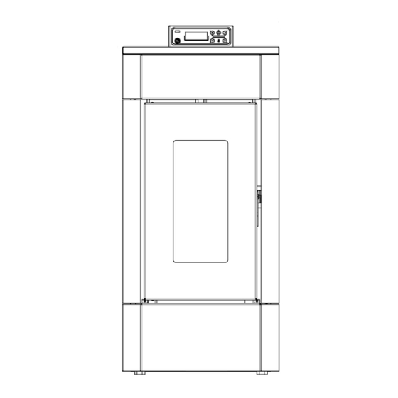
11.2 OVERALL DIMENSIONS Fig. 15 - General dimensions: EASY LEGEND Fig. 15 page 15 44 cm 92 cm 49 cm 21 cm 19,3 cm 11,5 cm 16,5 cm Exhaust fumes d.8 cm Hole combustion air inlet d.6 cm Fig. 16 - General dimensions: SWEET LEGEND Fig. -
Page 16: General Installation
LEGEND Fig. 16 page 15 48,5 cm 21 cm 21 cm 11,5 cm 18 cm Exhaust fumes d.8 cm Hole combustion air inlet d.6 cm 11.3 GENERAL INSTALLATION Fig. 17 - General installation LEGEND Stove Minimum lateral distance = 300 mm Minimum rear distance = 200 mm Minimum front distance = 1000 mm •... -
Page 17: Sweet Side Panel Disassembly
11.5 SWEET SIDE PANEL DISASSEMBLY For this model there is NO need to remove the frame to disassemble the side panels. To access the internal stove parts, disassemble the side panels as indicated below: • Loosen the 3 back screws (see Fig. 21 page 17). •... -
Page 18: Connection To The External Thermostat
• The plug must be easily accessible when the appliance is installed. • Please further assure you that your network is endowed with an efficient earth connection: if it does not exist or if it is not efficient, please endow you with one in compliance with the law. •... -
Page 19: Control Panel Display
• By using the stove the varnish inside the combustion chamber could be subjected to alterations. This occurrence can be attributed to different reasons: an excessive stove overheating, the presence of chemical agents in bad quality pellets, bad chimney draught, etc. Therefore varnish endurance in the combustion chamber cannot be guarantee. -
Page 20: Settings Menu
• Finally press “menu” to confirm and “esc” to exit. Timer setting (see relative chapter) Sleep setting (see relative chapter) 12.4 SETTINGS MENU The SETTINGS menu allows to act on the boiler operating mode: a - Language b - Cleaning (displayed only when the boiler is switched off) c - Screw Loading (displayed only when the boiler is switched off) d - Tone e - Ext.Thermostat (activation) -
Page 21: Info Menu
• Scroll to “Settings” using the arrows • Press “menu” to confirm. • Scroll to “Off Time Eco” using the arrows. • Press “menu” to confirm. • Enter the minutes with the + - keys. • Press “menu” to confirm and “esc” to exit. h - Pellet Recipe To change the recipe act as follows: •... -
Page 22: Failed Ignition
• If inside the combustion chamber there are booklets, manuals, etc..., remove them. • Check if the door is correctly closed. • Check if the stove is correctly inserted in the electric socket. • Before switching the stove on, assure you the burning pot is clean. •... -
Page 23: Programmed Mode (Timer) - Main Menu
Fig. 32 - Display Note: The full stop to the right of the ambient temperature shown in the control panel display (upper right) indicates the half degree (e.g. 23.° means 23.5°C). Air Fan Speed - this function allows selecting the desired speed for the ambient fans from 1 to 5 or A. A means automatic, ventilation depends on power, recommended setting (see Fig. -
Page 24: Programming Examples
At this point it will propose 00:00 as starting time, with key + - adjust the starting time and press the “menu” key to confirm. The next step proposes a shutdown time of 10 minutes above that set for start-up: press the + key and adjust the shutdown time, confirm with the “menu”... -
Page 25: Sleep Function (Main Menu)
• After 5 minutes from the beginning of the switch-off procedure. 12.15 SLEEP FUNCTION (MAIN MENU) The sleep function is activated only when the boiler is switched on and allows to quickly set a time at which the product must switch off. To set the Sleep function act as follows: •... -
Page 26: Pellet Supply
Fig. 40 - Remove nut Fig. 41 - Digital pressure switch connection DATA Stove depression 22,5/24,5 Pa - 41,5/44,5 Pa - 57,5/59,5 Pa - - temperature 6,5 68/70 Pa - 135°C 79/81 Pa - 153°C 94°C 105°C 120°C NB: for good combustion, the depression values must be between + -5 Pa and the temperature values between + - 10°C. -
Page 27: Remote Control
Fig. 44 - Door open Fig. 45 - Timer: 90 seconds To operate correctly, the stove must work with the pellet hopper door always closed; should it remain open for more than 90 seconds, the stove switches off. 12.22 REMOTE CONTROL •... -
Page 28: Smoke Temperature Probe
- clogged exhaust - Significant negative (wind) - clogged fume passages - open pellet loading tank - open fire door or worn/broken gaskets. 13.3 SMOKE TEMPERATURE PROBE Detects the temperature of the smoke, thereby enabling start-up or stopping the product when the temperature drops below the preset value. -
Page 29: Alarm Reset
PANEL ALERT TYPE OF PROBLEM SOLUTION The fire goes off abnormally. Check the level of pellets in the hopper. Wait for the cooling stage to end, cancel the alarm and restart the boiler setting the fuel loading at minimum (SETTINGS menu - Pellet Recipe). The temperature of the pellets hopper or the A03 Thermostat water temperature exceed the envisioned... -
Page 30: Hopper And Auger Cleaning
Fig. 47 - Burning pot extraction Fig. 48 - Ash tray extraction Fig. 49 - Burning pot cleaning • Extract the burning pot (see Fig. 47 page 30) from its seat and empty it from the ash. • Extract the ash tray (see Fig. 48 page 30) and empty it from the ash. •... -
Page 31: Fume Chamber Cleaning
The hand rejector grid must not ever be removed fron its housing. Clean the hopper bottom and the visible part of the auger exclusively as shown in the picture (see Fig. 52 page 30). 14.4 FUME CHAMBER CLEANING Every 4/8 weeks the fume chamber cleaning must be executed. For the Sweet model: you need to remove the frame (see SWEET SIDE PANEL DISASSEMBLY page 17). -
Page 32: Fume Conduit Cleaning
Fig. 57 - Top deflector Fig. 58 - Right flue gas pass removal • Remove the top deflector (see Fig. 57 page 32). • Remove the right deflector (see Fig. 58 page 32). • Clean with a pipe cleaner and suction any ash accumulated inside. •... -
Page 33: Fume Pipes Annual Cleaning
Fig. 60 - Room fan cleaning • Remove the sides. • Remove dust build-up using a brush or a vacuum cleaner (see Fig. 60 page 33). 14.8 FUME PIPES ANNUAL CLEANING Clean once a week from soot with brushes. The cleaning operation must be executed by a specialized stove-repairer who will provide for the cleaning of fume pipe, chimney flue and chimney pot. -
Page 34: In Case Of Anomaly
IN CASE OF ANOMALY 15.1 PROBLEM SOLVING Before of every Authorized Technician intervention, the same Technician has the duty to check if the parameters of the mother board correspond to those of the table you own. In case of doubts regarding the use of the stove, please contact ALWAYS the Authorized Technician on order to avoi irreparable damages! PROBLEM CAUSE... - Page 35 PROBLEM CAUSE SOLUTION INTERVENTION Empty hopper Full the hopper. Auger blocked by a foreign object Clean the auger. (for example nails) The fire extinguish and the stove Bad quality pellets Try other types of pellets. stops Pellet drop value Adjust the pellet loading. too low "phase 1"...
-
Page 36: Technical Datas
PROBLEM CAUSE SOLUTION INTERVENTION Check that the flue is not clogged. The stove's smoke Low smoke duct produces Increase stove power to minimum (pellet drop and fan revs). temperature condensation Install condensation collection cup. TECHNICAL DATAS 16.1 REPAIR INFORMATION Now we give some instructions for the Authorized Technician to take into consideration to have access to stove mechanical components. -
Page 37: Features
16.2 FEATURES DESCRIPTION EASY SWEET WIDTH 44 cm 47 cm DEPTH 49 cm 48,5 cm HEIGHT 92 cm 94 cm WEIGHT 62 kg 64 kg INTRODUCED THERMIC POWER (Min/Max) 2,6 - 7 kW 2,5 - 7 kW NOMINAL THERMIC POWER (Min/Max) 2,4 - 6,5 kW 2,4 - 6,5 kW EFICIENCY (Min/Max) - Page 38 NOTE...
- Page 39 NOTE...
- Page 40 · pellet stoves wood stoves wood cooking stoves · thermostoves pellet fireplace inserts CADEL srl FREEPOINT by Cadel Via Foresto Sud, 7 31025 Santa Lucia di Piave (TV) - ITALY tel. +39.0438.738669 fax +39.0438.73343 www.cadelsrl.com Partner of: Rev.00 - 2016...
Need help?
Do you have a question about the EASY-SWEET 3 and is the answer not in the manual?
Questions and answers