
Related Manuals for Panasonic DMR-XS350EB


Summary of Contents for Panasonic DMR-XS350EB
- Page 1 ORDER NO.DSD0906025CE DVD Recorder DMR-XS350EB Model No. Vol. 1 Colour (K).......Black Type © Panasonic Corporation 2009. Unauthorized copying and distribution is a violation of law.
-
Page 2: Table Of Contents
TABLE OF CONTENTS PAGE PAGE 1 Safety Precautions -----------------------------------------------3 1.1. General guidelines -----------------------------------------3 2 Warning --------------------------------------------------------------4 2.1. Prevention of Electrostatic Discharge (ESD) to Electrostatic Sensitive (ES) Devices ---------------4 2.2. Precaution of Laser Diode -------------------------------5 2.3. Service caution based on legal restrictions----------6 3 Service Navigation------------------------------------------------7 3.1. -
Page 3: Safety Precautions
1 Safety Precautions 1.1. General guidelines 1. When servicing, observe the original lead dress. If a short circuit is found, replace all parts which have been overheated or damaged by the short circuit. 2. After servicing, see to it that all the protective devices such as insulation barriers, insulation papers shields are properly installed. -
Page 4: Warning
2 Warning 2.1. Prevention of Electrostatic Discharge (ESD) to Electrostatic Sensitive (ES) Devices Some semiconductor (solid state) devices can be damaged easily by static electricity. Such components commonly are called Elec- trostatic Sensitive (ES) Devices. Examples of typical ES devices are integrated circuits and some field-effect transistor-sand semi- conductor "chip"... -
Page 5: Precaution Of Laser Diode
2.2. Precaution of Laser Diode... -
Page 6: Service Caution Based On Legal Restrictions
2.3. Service caution based on legal restrictions 2.3.1. General description about Lead Free Solder (PbF) The lead free solder has been used in the mounting process of all electrical components on the printed circuit boards used for this equipment in considering the globally environmental conservation. The normal solder is the alloy of tin (Sn) and lead (Pb). -
Page 7: Service Navigation
3 Service Navigation 3.1. How to format for HDD when replacement of HDD or Power/ IF P.C.B. 3.1.1. How to escape " HDD Error " indication on GUI display. 1. When exchange HDD or Power/ IF P.C.B., the " HDD Error " screen is displayed, but, according to a following procedure, please format HDD. - Page 8 3. Turn on OK button, after choose a position of the " HDD/Disc " at the " Setup " stage. (Shown in Reference screen 4) (Reference screen 4) 4. Turn on and hold OK button for over 3 second, after choose a position of the " HDD Management " at the " HDD/Disc " stage. (Shown in Reference screen 5) (Reference screen 5) 5.
-
Page 9: Service Information
3.2. Service Information 3.3. Caution for DivX... -
Page 10: Hdd/Dvd Drive) Service Navigation
3.4. (HDD/DVD Drive) Service Navigation 3.4.1. HDD/DVD Drive Simple check Perform simple quality judgement process of HDD/DVD Drive according to the following operations. 1. Execute Service Mode While the power is off, press [CH UP], [REC] and [OPEN/CLOSE] keys simultaneously for five seconds. 2. -
Page 11: Operation Check When A Usb Device Is Connected
3.5. Operation check when a USB device is connected You can check the operation status (normal or abnormal) of the USB connection part of this unit easily as shown below. Connect each device to the USB terminal on the front panel and check the operation status on the TV monitor. Normal operation: Automatically displayed when the USB connection is made to a digital camera, etc. - Page 12 Main functions 1. Execute Tuner Service Mode Turn the power on to receive digital broadcasting (HD broadcasting). Press and hold [POWER] (Unit Key) and press [OPEN/CLOSE] + [REC] for 5 seconds at the same time. 2. Finishing Service Mode Method 1: After turning the unit “OFF”, pull out the AC cord. Method 2: Repeat turning ON and OFF twice: P-OFF →...
- Page 13 Note : Hard test result does not guarantee that problems do not exist even if the result is OK. The result is used as reference when any trouble occurs. 3.6.2. Use times and number of times of Power ON/OFF Display accumulated time of Power ON and display number of times of Power ON/OFF. *1 : Display accumulated time of Power ON Display on a 15-minute basis 00123:15 →...
- Page 14 Operation procedure Preparation: Prepare a SD card to export data stored in this unit. Create the following directory on the SD card. EEPBAKSD Boot: 1. On Tuner Service Mode display Using Remote Controller, move the cursor to user’s setting information backup display position (Refer to below) on Tuner Service Mode display.
-
Page 15: Specifications
4 Specifications... -
Page 17: Location Of Controls And Components
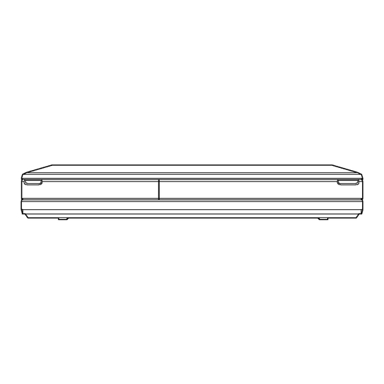
5 Location of Controls and Components... -
Page 19: Installation Instructions
6 Installation Instructions 6.1. Taking out the Disc from DVD-Drive Unit when the Disc cannot be ejected by OPEN/CLOSE button 6.1.1. Forcible Disc Eject 6.1.1.1. When the power can be turned off. 1. Turn off the power and press [STOP] [CH UP] keys on the front panel simultaneously for 5 seconds. 6.1.1.2. - Page 20 1. Turn off the power and pull out AC cord. 2. Remove the Top Case. 3. Put deck so that bottom can be seen. 4. Slide SLIDE CAM by Eject Pin (JZS0484) or minus screw driver (small) in the direction of arrow to eject tray slightly. 5.
-
Page 21: Service Mode
7 Service Mode 7.1. Self-Diagnosis and Special Mode Setting 7.1.1. Self-Diagnosis Functions Self-Diagnosis Function provides information for errors to service personnel by “Self-Diagnosis Display” when any error has occurred. U**, H** and F** are stored in memory and held. You can check latest error code by transmitting [0] [1] of Remote Controller in Service Mode. Automatic Display on LCD will be cancelled when the power is turned off or AC input is turned off during self-diagnosis display is Error Code Diagnosis contents... - Page 22 Error Code Diagnosis contents Description Monitor Display Automatic LCD display HDMI connection error When authentication error occurs while the No display (authentication error) equipments (TV, amplifier etc.) are con- nected by HDMI. (or when there is a prob- lem with the HDMI cable) U73 display disappears when error has been solved by Power OFF/ON of connecting equipment or by...
- Page 23 Error Code Diagnosis contents Description Monitor Display Automatic LCD display NO READ Disc read error *A disc is flawed or dirty. “Cannot read. *A poor quality failed to start. Please check the *The track information could not be read. disc.” HARD Drive error The drive detected a hard error.
- Page 24 7.1.2. Special Modes Setting Item LCD display Key operation Mode name Description Front Key Rating password The audiovisual level setting password is Open the tray, set DRIVE SELECT initialized to “Level 8”. to DVD, and press [REC] and [PLAY] simultaneously for 5 sec- onds.
- Page 25 Aging Overview • Record several programs onto the mounted HDD with DR mode until the recording capacity becomes full. Then play back all the recorded programs (including special playback). • When the remaining capacity becomes almost zero due to multiple recordings, the disc is formatted, recording is made onto the same disc again and playback starts.
- Page 26 Sequence 0: OPEN/CLOSE of DVD drive tray Press [OPEN/CLOSE] to open the tray, then inserting discs. Press [OPEN/CLOSE] to close the tray. Key operation Execution time Contents (Second) Press [STOP] button 10 Sec. Countermeasure of press unit button simultaneously. Press [OPEN/CLOSE] button 15 Sec.
- Page 27 Sequence 2: Details of Record/ Playback HDD: Record/ HDD: Playback Key operation Execution time Contents (Second) Press [0] button 2 Sec. Press [0] button. (Select the 0001 CH) Press [0] button 2 Sec. Press [0] button. Press [0] button 2 Sec. Press [0] button.
- Page 28 Sequence 3: Detail of copying. (HDD to DVD) Recorded to the DVD. Key operation Execution time Contents (Second) Press [PLAYBACK] button 10 Sec. Playback the program at the time of the EE screen. Press [SUB MENU] button 10 Sec. Move the cursor to [Screen Mode Select] of the sub menu screen. Press [UP CURSOR] button 2 Sec.
- Page 29 Key operation Execution time Contents (Second) Press [FAST REWIND] button 4 Sec. Playback by [Fast Rewind 2]. Press [FAST REWIND] button 4 Sec. Playback by [Fast Rewind 3]. Press [FAST REWIND] button 4 Sec. Playback by [Fast Rewind 4]. Press [FAST REWIND] button 4 Sec.
- Page 30 Item LCD display Key operation Mode name Description Front Key Demonstration lock/ Ejection of the disc is prohibited. *When lock the tray. When the power is on, press unlock The lock setting is effective until unlocking [STOP] and [POWER] keys simulta- the tray and not released by “Main unit ini- neously for 5 seconds in the condi- tialization”...
- Page 31 Item LCD display Key operation Mode name Description (Remote controller key) ROM Version Display 1. Region code (displayed for 5 sec.) Press [0] [2] in service mode 2. Main firm version (displayed for 5 sec.) 3. Timer firm version (displayed for 5 sec.) 4.
- Page 32 Item LCD display Key operation Mode name Description (Remote controller key) READ SEEK Inspecting seek time of HDD to inspect per- At start Press [3] [1] in service mode. Inspection formance. * When canceling the inspection mode while executing, do “forced power-off”.
- Page 33 Item LCD display Key operation Mode name Description (Remote controller key) READ VERIFY Measure of access time in READ VERIFY At start Press [3] [2] in service mode. Inspection MODE of HDD. * When canceling the inspection mode while executing, do “forced power-off”.
- Page 34 Item LCD display Key operation Mode name Description (Remote controller key) HDD High Speed Scan High speed AV scan check of HDD Press [3] [6] in service mode. The [*] sign is added every 10 sec- onds while inspecting. Two digits on the right side are the progress level of the inspection (The unit is %).
- Page 35 Item LCD display Key operation Mode name Description (Remote controller key) HDD/DVD Drive Simple Check if HDD Self-Diagnosis test was per- HDD Self-Diagnosis test start. Press [3][8] in service mode. Check formed or Drive last error occurred within 4 weeks. * If the current date or the date when the error occurred is wrong, correct judgement may not be made.
- Page 36 Item LCD display Key operation Mode name Description (Remote controller key) DVD Drive Last Error DVD Drive error code display. 1. Error Number is displayed for 5 Press [4] [2] in service mode. *For details about the drive error code, refer seconds.
- Page 37 Item LCD display Key operation Mode name Description (Remote controller key) 6. Disc Maker ID is displayed for 5 seconds. In case that the maker cannot be identified, display is black out. 7. Factor of Drive Error (hexadecimal) occurring is left displayed...
- Page 38 Item LCD display Key operation Mode name Description (Remote controller key) Laser power confirmation Drive state is judged based on difference into between laser power value at shipping and RAM Drive in service mode. present laser power value. (Other media are assumed to be non-correspondence.) 2.
- Page 39 Item LCD display Key operation Mode name Description (Remote controller key) CEC (L) output Check of the CEC terminal low output of Press [5] [6] in service mode. HDMI. Production Date Display Display the date when the unit was pro- Press [6] [1] in service mode.
- Page 40 Item LCD display Key operation Mode name Description (Remote controller key) Delete the Laser Used Laser used time stored in the memory of the Press [9] [5] in service mode. Time unit is deleted. Delete the Last Drive Delete the Last Drive Error information Press [9] [6] in service mode.
-
Page 41: Service Fixture & Tools
8 Service Fixture & Tools Part Number Description Compatibility RFKZ0216 Extension Cable (Digital P.C.B. - AV IO P.C.B. / 23 Pin) Same as EH50 Series RFKZ0216 Extension Cable (Digital P.C.B. - Power/IF P.C.B. / 23 Pin) Same as EH50 Series RFKZ0323 Extension Cable (Digital P.C.B. -
Page 42: Disassembly And Assembly Instructions
9 Disassembly and Assembly Instructions 9.1. Unit 9.1.1. Disassembly Flow Chart The following chart is the procedure for disassembling the casing and inside parts for internal inspection when carrying out the ser- vicing. To assemble the unit, reverse the steps shown in the chart below. 9.1.2. -
Page 43: Top Case
9.1.3. Top Case 9.1.5. Front (L) P.C.B., Front (R) P.C.B. 1. Remove 2 Screws (A) and 3 Screws (B). 1. Remove 4 Screws (A) to remove the Front (L) and Front 2. Slide the Top Case rearward and open the both ends at (R) P.C.B. -
Page 44: Dvd Drive
9.1.6. DVD Drive 2. Attach the Tray door ass’y in order from • Insert the Long shaft in the hole. 1. Remove 3 Screws (A), DVD Power cable and FFC to • Insert the shaft in the hole. remove DVD Drive. CAUTION: 3. - Page 45 9.1.7. 1. Remove 4 Screws (A), Digital-HDD cable and HDD Power cable to remove HDD. 2. Put HDD up and down inversely so as not to give a shock to HDD. 3. Remove 4 Screws (B) to remove HDD from HDD bracket.
-
Page 46: Rear Panel With Fan Motor
Rear Panel, Fan Motor Coaxial P.C.B. 9.1.8. 9.1.9. 1. Pull out Coaxial P.C.B. in the direction of arrow. 9.1.8.1. Only Fan Motor 1. Remove 2 Screws (A) and disconnect the Fan connector. 2. Set free Fan connector wire from Wire Clamper. 3. - Page 47 Digital P.C.B. Power/ IF P.C.B. 9.1.11. 9.1.13. 1. Disconnect FFC. 2. Disconnect 6 connectors. 3. Remove 4 Screws (A) to remove Digital P.C.B. 1. Disconnect DVD Power cable. 2. Disconnect 4 connectors. 3. Remove 3 Screws (A) to remove Power/ IF P.C.B. 9.1.12.
-
Page 48: Dvd Drive
9.2. DVD Drive 9.2.1. Disassembling of Traverse Base Ass’y, Drive P.C.B. and SW P.C.B. Though the Traverse Base Ass’y, Drive P.C.B. and SW P.C.B. are not supplied as Replacement Parts, these are necessary to disassemble for when other parts are replaced. 1. - Page 49 Note: If fore of the Drive is not lifted, the guide at the both sides will not be slide to the back and can not remove the Tray. 5. The Slide cam is slide in the arrow direction fully. • Installation for Tray a.
- Page 50 6. Remove 2 Screws (B), 3 FFCs and FPC to remove Drive • Installation for Traverse unit P.C.B. a. The 2 projection parts rearward of Middle chassis are fitted into the concave of Mechanism chassis. 7. The lever is pulled in the arrow direction while pushing the lever of back of Slide cam with your finger.
- Page 51 8. The 4 Screws (C) are unscrewed. 10. The Belt and Screw (D) are removed. The 2 Claws of Mechanism chassis are pushed to the inside and frame is removed from Mechanism chassis. 11. The 2 Screws (E) are unscrewed and whole SW P.C.B. is removed.
- Page 52 9.2.2. Upper base ass’y 4. The Clamp cover is removed. 1. Procedures 1,2 of “9.2.1. Disassembling of Traverse Base Ass’y, Drive P.C.B. and SW P.C.B.” is performed in this section. is pushed with precision (-) screw driver and the Rail is removed.
- Page 53 9.2.3. 9.2.6. Loading motor 1. Procedures 1-7 of “9.2.1. Disassembling of Traverse 1. Procedures 1-11 of “9.2.1. Disassembling of Traverse Base Ass’y, Drive P.C.B. and SW P.C.B.” is performed in Base Ass’y, Drive P.C.B. and SW P.C.B.” is performed in this section.
- Page 54 3. The stopper is pushed inside and Drive gear is pulled out. 9.2.8. Switch lever 1. “9.2.4. Slide cam” is performed. 2. The projection of Switch lever is pushed while lifting rear- ward, and Switch lever is removed from Claws. 4.
- Page 55 Notes for installation of Switch lever ass’y 3. The Opener roller is removed while pushing Opener lever • The Spring is set to the projection of chassis and first, to inside. is fitted and is latched into the concave firmly. 9.2.10.
- Page 56 Installation for Rail Throw in the groove of Rail and Tray and slide to the fore of Tray.
- Page 57 9.2.11. Grease...
- Page 58 9.2.12. How to Clean the Lens of Optical Pick-UP Follow the “9.2.1. Upper Base Ass’y”...
- Page 59 Service hint If a defective phenomenon is “NO READ”, please try to clean TT (turn table) in the drive in according to the following procedure. 1. Blow off dust on TT by a blower. (Air must not blow to it strongly.) 2.
-
Page 60: Measurements And Adjustments
10 Measurements and Adjustments 10.1. Service Positions Note: For description of the disassembling procedure, see the section 9. 10.1.1. Checking and Repairing of Power / IF P.C.B. - Page 61 10.1.2. Checking and Repairing of DVD Drive...
- Page 62 10.1.3. Checking and Repairing of AV IO P.C.B.
- Page 63 10.1.4. Checking and Repairing of HDD...
- Page 64 10.1.5. Checking and Repairing of Digital P.C.B.
-
Page 65: Caution For Replacing Parts
10.2. Caution for Replacing Parts 10.2.1. Items that should be done after replacing parts * Note1: 10.2.2. Notice after replacing Digital P.C.B. or DVD Drive Formatting the HDD is unnecessary after replacing Digital P.C.B. or DVD Drive. [TM AV1] is displayed, once power OFF, and power ON again. -
Page 66: Standard Inspection Specifications After Making Repairs
Perform auto recording and playback for one minute using the RAM No abnormality should be seen in the picture, sound or operation. disc. *Panasonic DVD-RAM disc should be used when recording and playback. Model with the HDD: Perform auto recording and playback for one No abnormality should be seen in the picture, sound or operation. -
Page 67: S1. About Indication Of The Schematic Diagram
"Standard-Playback" mode when there is no specify mode is mentioned. Model No. DMR-XS350EB 4.Although the voltage and waveform available on here is measured with standard frame, it may be differ from actual measurement due to modification of circuit and so on. -
Page 68: S2. Voltage And Waveform Chart
S2. Voltage and Waveform Chart Note) Indicated voltage values are the standard values for the unit measured by the DC electronic circuit tester (high-impedance) with the chassis taken as standard. Therefore, there may exist some errors in the voltage values, depending on the internal impedance of the DC circuit tester. S2.1. -
Page 69: S2.2. Av Io P.c.b
S2.2. AV IO P.C.B. <IC3001> <P3005> REF No. PIN No. REC REF No. PIN No. REC REF No. PIN No. REC IC3001 IC3001 P3003 IC3001 P3003 IC3001 IC3001 P3003 IC3001 IC3001 IC3001 P3003 IC3001 IC3001 P3003 IC3001 P3003 IC3001 IC3001 P3003 IC3001 IC3001... -
Page 70: S2.3. Coaxial P.c.b
S2.3. COAXIAL P.C.B. S2.4. Front_R P.C.B. S2.5. S_Tuner P.C.B. REF No. PIN No. REC REF No. PIN No. REC REF No. PIN No. REC Q4801 IC7201 IC8700 Q4801 IC7201 IC8700 Q4801 IC7201 IC8700 IC7201 IC8700 IC7201 IC8700 IC7201 IC8701 IC7201 IC8701 IC7201 IC8701... -
Page 71: S3. Block Diagram
TIMER BLOCK IC59502- SECTION D10101 D11305 D10102 Q10101 (POWER CONT.) IC12201 D11303 (ERROR VOLTAGE DET.) Q12201 (FEED BACK) IC14301 Q14302 (DC-DC CONVERTER) (REG.X SW+5.8V) EXT UP Q10102 (FEED BACK) QR10101 (S P SAVE :OFF) COLD DMR-XS350EB Power Supply Block Diagram(1/2) -
Page 72: S3.1.2. Power Supply Block Diagram (2
P6702 P58005 V OUT 3 DIGITAL P.C.B. IC6801 IC6802 (REG. USB +5V) (Protector) SMT +5V V OUT 3 V IN V OUT V IN FROM XN+3.3V P58006 P6703 XN+3.3V P7901 P7201 DIGITAL FRONT(R) P.C.B. P.C.B. DMR-XS350EB Power Supply Block Diagram(2/2) -
Page 73: S3.2. S-Tuner P.c.b. Regulator Block Diagram
2 LNB_A 13,14 TUNER +3.3V DEMOD +3.3V IC8702 (REG.+1V) DEMOD +1V VOUT DEMOD +1V 3 CE 8 TU SDA 9 TU SCL IC8704 (REG.+3.3V) +3.3V VOUT IC8701, IC8703 X SW+3.8V PP58012 PS8703 1 VIN DMR-XS350EB S-Tuner P.C.B. Regulator Block Diagram... -
Page 74: S3.3. Analog Video Block Diagram
DIGITAL P.C.B. < G G IN A > (DECODER/ EXT) AV2 B AV2 G P3005 P58002 BLUE CLAMP < G B IN A > AV2 V/Y VIDEO/Y AV2 B TUNER CLAMP CLAMP AV2 V/Y CLAMP DMR-XS350EB Analog Video Block Diagram... -
Page 75: S3.4. Analog Audio Block Diagram
IIC CLK FROM IC59502- IIC BUS TIMER LOGIC P3005 P58002 IIC DATA SECTION IC59502- JK4901 DIGITAL AUDIO OUT (OPTICAL) FROM P58002 P3005 IEC OUT P4901 P4801 DIGITAL JK4801 P.C.B. DIGITAL AUDIO OUT Q4801 (COAXIAL) BUFFER DMR-XS350EB Analog Audio Block Diagram... -
Page 76: S3.5. Timer Block Diagram
P7201 P7901 P6702 P58005 COM0 KEY IN3 COM0 - COM3 PLAY CH UP COM3 S7202 S7203 P58006 P6703 P7407 P7201 BACK LIGHT 30 LED BACK P7203 FRONT (L) P.C.B. BACK LIGHT QR7204,Q7204 (BACK LIGHT DRIVE) DMR-XS350EB Timer Block Diagram S-10... -
Page 77: S4. Schematic Diagram
CS0- CS0- FRONT_L_IN KEYIN2 CS1- CS1- XN5V LCD/FL_CLK DASP_NC1 DASP_NC1 BACK_LIGHT LCDFL_CS DIGITAL P.C.B. P1603 DR 5V DR 5V DR GND DR GND DR GND DR GND DR 12V DR 12V DMR-XS350EB DVD DRIVE POWER/IF P.C.B. Interconnection Schematic Diagram S-11... -
Page 78: S4.2. Power (P) Schematic Diagram
S4.2. Power (P) Schematic Diagram DMR-XS350EB Power Section (Power/IF P.C.B.(1/2)) Schematic Diagram (P) CAUTION: FOR CONTINUED PROTECTION AGAINST FIRE HAZARD, REPLACE ONLY WITH THE SAME TYPE 2A 250V FUSE. ATTENTION: POUR UNE PROTECTION CONTINUE LES RISQUES 2A 250V D' INCENDIE N' UTILISERQUE DES FUSIBLE DE MÉME TYPE 2A 250V. - Page 79 DMR-XS350EB Power Section (Power/IF P.C.B.(1/2)) Schematic Diagram (P) Q14202 B1DHED000008 C14211 IC14201 C0DBAYY00475 L14202 K14202 R14206 VWJ0795=5 G0A100K00003 D1BFR0270001 DR_5V R14212 QR14202 EXT-Up $(33K) C14203 C14205 R14202 33K[G] QR14201 Vref/SS C14206 C14204 R14201 R14214 3300P 2700[G] 5600[G] R14203 56K[G] K14201...
- Page 80 D11304 B0AADM000003 B0HAGM000006 B0AADM000003 B0HAGM000006 R13201 ERJ6GEYJ332V ERJ6GEYJ332V Modify Category R13202 ERJ6GEYJ332V ERJ6GEYJ332V Variation Type BW850GL/BW750GL/BW850GZ R13203 BS850EB/BS750EB XW450GL/XW350GL/XW350GZ VSC5603-A│ VSC5713-A│ VSC5603-A│ VSC5713-A│ ZA11301 XS350EB VSC5603 VSC5713 VSC5603 VSC5713 ZA11302 ZA13202 DMR-XS350EB Power Section (Power/IF P.C.B.(1/2)) Schematic Diagram (P) S-14...
- Page 81 C14303 C14305 R14302 33K[G] Vref/SS QR10101 C14304 R14301 R14312 B1GBCFNN0043 C14306 3300P 2700[G] 5600[G] DRGND R12207 $[D](27K) R14303 56K[G] DDGND G11000 QR10103 $[B1GBCFNN0041] S_P_SAVE_L Confidential 2009/12/31 Until ZA11302 XYN3+J8FJ ZA13202 XYN3+J8FJ DMR-XS350EB Power Section (Power/IF P.C.B.(1/2)) Schematic Diagram (P) S-15...
-
Page 82: S4.3. Sd/Dv/Usb (S) Schematic Diagram
C3843 F2A1C471A702 F2A1C471A702 F2A1C4710055 XW450GL/XW350GL/XW350GZ JK3801 K2HA307B0006 K2HA307B0006 K2HA107B0002 XS350EB JK3802 K2HZ106B0010 K2HZ106B0010 K2HZ106B0011 CPRM KEY1 ZS6701 VFV0164 DMR-XS350EB K7901 ERJ3GEY0R00V ERJ3GEY0R00V $[ERJ3GEY0R00V] HDD CPRM KEY1 ZS6702 VFV0167 P1601 K1KA04AA0301 K1KA04AA0301 $[K1KA04AA0301] MAC ADDRESS1 ZS6703 VFV0179 SD/DV/USB Section P1603 $[K1KA04AA0193]... - Page 83 S-17...
-
Page 84: S4.4. Av Io Schematic Diagram
S4.4. AV IO Schematic Diagram DMR-XS350EB AV IO Schematic Diagram R4046 R4055 C4063 R4076 R4090 D0HB912ZA002 D0HB153ZA002 F2A1C470B174 R4077 C3957 R3930 D4005 C4033 MA3Z142D0LG F2A1C470B174 Q4006 R3991 R3992 R3993 R3988 C4060 2SD132800L C3958 C4018 C3959 R3987 33P[22] R4078 C4092 5600... - Page 85 DMR-XS350EB AV IO Schematic Diagram Modify Category Variation Type BW850GL/BW750GL/BW850GZ BS850EB/BS750EB XW450GL/XW350GL/XW350GZ C3957 R3930 XS350EB VariationCategory R3988 C3910 $[F2A1H100A236] F2A1V100A534 $[F2A1H100A236] F2A1V100A534 C3958 R3987 R3989 C3911 $[F2A1H100A236] F2A1V100A534 $[F2A1H100A236] F2A1V100A534 C3951 R3990 C3914 $[F2A1H100A236] F2A1V100A534 $[F2A1H100A236] F2A1V100A534 C3952 C3915 $[F2A1H100A236]...
- Page 86 SD_COUT SD_YOUT CL3032 DGND CL3033 P_SAVE_L CL3034 HD_PR_OUT DGND CL3035 HD_Y_OUT CL3036 DGND HD_PB_OUT CL3037 DGND CL3038 G_R_IN_A G_G_IN_A CL3039 G_B_IN_A CL3040 SUB_A5V CL3041 G_OPTIEC_B P4901 K1KA05AA0031 SUB_A5V DGND DGND DGND G_OPTIEC_B C4902 C4901 DMR-XS350EB AV IO Schematic Diagram S-20...
- Page 87 R3058 VWJ0795=12.5 K3006 VWJ0795=10 R3056 C3064 AV4IN_Y S_IN_L REAR_C OUT R3059 REAR_Y OUT R3057 Confidential C3046 C3045 F2A0J331A832 F2A0J102A833 6.3V R3009 75[F] 2009/12/31 Until 6.3V R3010 75[F] ZJ3002 C3047 6.3V R3011 75[F] K9ZZ00001279 F2A0J331A832 DMR-XS350EB AV IO Schematic Diagram S-21...
-
Page 88: S4.5. Coaxial Schematic Diagram
CK7002 C4803 KEY_POWER CK7003 JK4801 F2A1E470A205 C4806 C4805 $[F2A0J470A599] R4804 R4806 R4805 R4807 Modify Category Variation Type BW850GL/BW750GL/BW850GZ BS850EB/BS750EB Confidential Confidential XW450GL/XW350GL/XW350GZ Until 2009/12/31 Until XS350EB 2009/12/31 VariationCategory JK4801 K2HA102B0095 K2HA102B0096 DMR-XS350EB DMR-XS350EB COAXIAL Front_L Schematic Diagram Schematic Diagram S-22... -
Page 89: S4.7. Front_R Schematic Diagram
EVQ11A04M LB7204 IR7201 R7251 J0JYC0000070 C7204 (LCD HOLDER) $(0) R7241 R7218 120[22] R7204 R7211 Confidential R7240 $(10K) 3300 R_LCD5V CL7231 Until R7201 CK7232 C7202 4700 1u[ZF] LED_BACK CK7233 K1KA03AA0180 C7205 $(0.01) P7203 QR7204 R7242 UNR52A3J0L DMR-XS350EB Front_R Schematic Diagram S-23... -
Page 90: S4.8. S_Tuner Schematic Diagram
S4.8. S_Tuner Schematic Diagram DMR-XS350EB S_Tuner Schematic Diagram TU8701 J3BBCBC00005 CL8747 R8712 CL8713 NRESET NRESET CL8714 CH1ERR R8731 CL8744 CH1PSYNC R8734 CL8715 CL8748 CH1PSYNCS R8713 SYNC CL8746 CH1VAL R8735 CL8716 CL8749 CH1VALS R8714 D_PARITY CL8765 CH1CLK R8736 CL8717 CL8750 CH1CLKS... - Page 91 DMR-XS350EB S_Tuner Schematic Diagram P8700 $[K1MN40AA0082] P8701 $[K1MN40AA0082] R8770 CH1DATA7S2 R8771 CH1CLKS2 C8705 CH1CLKS R8772 CH1PSYNCS2 CH1DATA7S R8773 CH1VALS2 IC8701 C0JBAZ001652 CH1DATA7 CH0DATA7 CH1DATA7 CH0DATA7 CH1DATA6 CH0DATA6 CH1VALS CH1DATA6 CH0DATA6 CH1PSYNCS CH1DATA5 CH0DATA5 CH1DATA5 CH0DATA5 R8774 CH1DATA4 CH0DATA4 CH1DATA4 CH0DATA4...
- Page 92 G1C220M00055 CL8745 F1H1 LB8704 LB8711 CL8770 LNB_A P-GND AGND 13/18V 400mA C8706 R8751 CL8779 J0JHC0000021 J0JHC0000021 SDA1_PK LNB_B R8752 CL8780 SCL1_PK VCC-1 R8761 ADDR R8762 $(0) C8758 CL8777 F1H1 DSQOUT CL8778 R8750 R8753 DSQIN EXTM DMR-XS350EB S_Tuner Schematic Diagram S-26...
- Page 93 F1H1E224A068 ERJ8GEYJ150V P-GND AGND CL8786 8779 R8758 CL8787 8780 ERJ8GEYJ101V VCC-1 CL8788 C8760 C8762 F1H1E224A068 ADDR R8762 $(0) C8758 ECJ1VB1H104K D8754 F1H1E224A068 $[B0BC4R700007] DSQOUT Confidential CL8789 R8753 R8755 DSQIN EXTM Until ZA8701 RMN0899 R8757 $(0) DMR-XS350EB S_Tuner Schematic Diagram S-27...
-
Page 94: S5. Print Circuit Board
S5. Print Circuit Board S5.1. Power/IF P.C.B. DMR-XS350EB Power/IF P.C.B. (Component Side) S-28 S-28... - Page 95 DMR-XS350EB Power/IF P.C.B. (Foil Side) S-29 S-29...
- Page 96 (Component Side) DMR-XS350EB Power/IF P.C.B. (Component Side) S-30...
- Page 97 (Foil Side) DMR-XS350EB Power/IF P.C.B. (Foil Side) S-31...
-
Page 98: S5.2. Av Io P.c.b
S5.2. AV IO P.C.B. S5.2.1. AV IO P.C.B. (Component Side) JK3001 JK3002 JK4901 JK3901 C3928 R3924 C3045 C4007 C3012 C3917 C4027 C4067 C4005 C4092 ZJ3002 C4008 C4024 C4017 C3035 C4013 W100 W101 W102 W103 (Component Side) DMR-XS350EB AV IO P.C.B. (Component Side) S-32... -
Page 99: S5.2.2. Av Io P.c.b. (Foil Side
CL3038 CL4007 CL3039 CL4005 C3027 CL4006 C3034 R4094 C3026 R3976 CL3041 CL3033 R4066 R3975 CL3040 C3025 R3006 R3001 R3972 R4067 C3043 IC4012 C3069 LB4350 C3068 C3067 C3005 C4003 R4003 R4002 C4301 (Foil Side) DMR-XS350EB AV IO P.C.B. (Foil Side) S-33... -
Page 100: S5.3. Coaxial P.c.b
S5.3. COAXIAL P.C.B. / S5.4. Front_L P.C.B. P7001 CK7001 JK4801 CK7003 CK7002 Q4801 R4803 C4802 CL4801 (Component Side) (Foil Side) (Component Side) (Foil Side) DMR-XS350EB DMR-XS350EB COAXIAL P.C.B. Front_L P.C.B. S-34... -
Page 101: S5.5. Front_R P.c.b
S5.5. Front_R P.C.B. (Component Side) (Foil Side) DMR-XS350EB Front_R P.C.B. S-35... -
Page 102: S5.6. S_Tuner P.c.b
CL8772 CL8768 R8792 R8724 CL8727 R8794 CL8745 CL8739 LB8702 CL8741 R8726 CL8786 C8706 CL8729 C8730 C8722 C8716 CL8742 R8793 C8704 R8733 CL8740 LB8701 CL8728 CL8703 C8703 R8702 C8719 R8704 CL8738 R8742 CL8770 CL8747 C8790 (Foil Side) DMR-XS350EB S_Tuner P.C.B. S-36... -
Page 103: S6. Abbreviation
S6. Abbreviation INITIAL/LOGO ABBREVIATIONS A0~UP ADDRESS ACLK AUDIO CLOCK AD0~UP ADDRESS BUS ADATA AUDIO PES PACKET DATA ADDRESS LATCH ENABLE AMUTE AUDIO MUTE AREQ AUDIO PES PACKET REQUEST AUDIO RF SERVO AMP INVERTED INPUT SERVO AMP OUTPUT ASYNC AUDIO WORD DISTINCTION SYNC BIT CLOCK (PCM) BCKIN BIT CLOCK INPUT... - Page 104 INITIAL/LOGO ABBREVIATIONS DREQ DATA REQUEST DRESP DATA RESPONSE DIGITAL SERVO CONTROLLER DSLF DATA SLICE LOOP FILTER DIGITAL VIDEO DISC ERROR TORQUE CONTROL ERROR TORQUE CONTROL REFERENCE ENCSEL ENCODER SELECT ETMCLK EXTERNAL M CLOCK (81MHz/40.5MHz) ETSCLK EXTERNAL S CLOCK (54MHz) FBAL FOCUS BALANCE FCLK FRAME CLOCK...
- Page 105 INITIAL/LOGO ABBREVIATIONS PWMCTL PWM OUTPUT CONTROL PWMDA PULSE WAVE MOTOR DRIVE A PWMOA, B PULSE WAVE MOTOR OUT A, B READ ENABLE RFENV RF ENVELOPE RF PHASE DIFFERENCE OUTPUT (CD-ROM) REGISTER SELECT RSEL RF POLARITY SELECT RESET RESERVE SBI0, 1 SERIAL DATA INPUT SBO0 SERIAL DATA OUTPUT...
- Page 106 INITIAL/LOGO ABBREVIATIONS TPSO OP AMP OUTPUT TPSP OP AMP INVERTED INPUT TRCRS TRACK CROSS SIGNAL TRON TRACKING ON TRSON TRAVERSE SERVO ON VBLANK V BLANKING COLLECTOR POWER SUPPLY VOLTAGE VCDCONT VIDEO CD CONTROL (TRACKING BALANCE) DRAIN POWER SUPPLY VOLTAGE VIDEO FEED BACK VREF VOLTAGE REFERENCE SOURCE POWER SUPPLY VOLTAGE...
-
Page 107: S7. Replacement Parts List
S7. Replacement Parts List Note: 1.* Be sure to make your orders of replacement parts according to this list. 2. IMPORTANT SAFETY NOTICE Components identified with the mark have the special characteristics for safety. When replacing any of these components, use only the same type. 3. - Page 108 DMR-XS350EBK Ref.No. Part No. Part Name & Description Remarks Ref.No. Part No. Part Name & Description Remarks D13201 B0JBSG000047 DIODE 1 E.S.D. RFKB71149DT POWER/IF P.C.B. 1 (RTL)E.S.D. D14201 B0JCMD000014 DIODE 1 E.S.D. D14202 B0JCMD000014 DIODE 1 E.S.D. C1601 F2A1E3310075 25V 0.033U D14301 B0JCMD000014 DIODE...
- Page 109 DMR-XS350EBK Ref.No. Part No. Part Name & Description Remarks Ref.No. Part No. Part Name & Description Remarks R3801 ERJ3GEYJ750V 1/10W 75 R14311 ERJ3GEYG273V 1/10W 27K R3802 ERJ3GEYJ750V 1/10W 75 R14312 ERJ3GEYG562V 1/10W 5.6K R3803 ERJ3GEYJ750V 1/10W 75 R14401 ERJ3GEYG333V 1/10W 33K R3804 ERJ3GEYJ102V 1/10W 1K...
- Page 110 DMR-XS350EBK Ref.No. Part No. Part Name & Description Remarks Ref.No. Part No. Part Name & Description Remarks C3022 ECJ1VB1C104K 16V 0.1U C4082 ECJ2VC1H102J 50V 1000P C3023 ECJ1VC1H330J 50V 33P C4083 ECJ2VC1H102J 50V 1000P C3024 ECJ1VB1C104K 16V 0.1U C4092 F2A1C471A637 16V 470U C3025 ECJ1VB1C104K 16V 0.1U...
- Page 111 DMR-XS350EBK Ref.No. Part No. Part Name & Description Remarks Ref.No. Part No. Part Name & Description Remarks R3932 ERJ3GEYJ750V 1/10W 75 R3934 ERJ3GEYJ750V 1/10W 75 R4802 ERJ3GEYJ102V 1/10W 1K R3935 ERJ3GEYJ750V 1/10W 75 R4803 ERJ3GEYJ102V 1/10W 1K R3975 ERJ3GEYJ101V 1/10W 100 R4804 ERJ3GEYJ102V 1/10W 1K...
- Page 112 DMR-XS350EBK Ref.No. Part No. Part Name & Description Remarks Ref.No. Part No. Part Name & Description Remarks C8712 F1J10J226A104 6.3V 22U R8704 ERJ3GEYJ330V 1/10W 33 C8716 F1J0J106A014 6.3V 10U R8712 ERJ3GEYJ470V 1/10W 47 C8717 F1J0J106A014 6.3V 10U R8713 ERJ3GEYJ330V 1/10W 33 C8718 ECJ1VB1C104K 16V 0.1U...
- Page 113 DMR-XS350EBK Ref.No. Part No. Part Name & Description Remarks Ref.No. Part No. Part Name & Description Remarks RMG0739-K FLOATING RUBBER RMG0748-K HDD CUSHION 1 (RTL) RMG0748-K HDD CUSHION RMG0748-K HDD CUSHION VMD5402-2 MECHA CHASSIS RMG0748-K HDD CUSHION VMG1719 DAMPER VEE1E27 HDD POWER CABLE VMG1719 DAMPER...
-
Page 114: S8. Exploded View
S8. Exploded View S8.1. Frame and Casing Section (1) 73 74 S-48... -
Page 115: S8.2. Frame And Casing Section (2
S8.2. Frame and Casing Section (2) 38-2 38-5 38-9 38-4 38-6 38-3 38-7 38-7-1 38-10 38-8 S-49... -
Page 116: S8.3. Mechanism Section
S8.3. Mechanism Section S-50... -
Page 117: S8.4. Packing Parts And Accessories Section
S8.4. Packing Parts and Accessories Section A4-1 BATTERY (REMOTE CONT.) S-51...
Need help?
Do you have a question about the DMR-XS350EB and is the answer not in the manual?
Questions and answers