
Subscribe to Our Youtube Channel
Related Manuals for IKUSI R70


Summary of Contents for IKUSI R70
- Page 1 R 70 USER’s MANUAL Paseo Miramón 170 - 20014 Donostia - San Sebastián, Guipúzcoa /Spain - tlc@ikusi.com...
-
Page 2: Safety Instructions
Avoid knocking or dropping the set. • Do not use the set if failure is detected. REMEMBER Changes or modifi cati ons not expressly approved by IKUSI could void the user’s authority to operate this equipment. Cr 1 Tx Cr 1... -
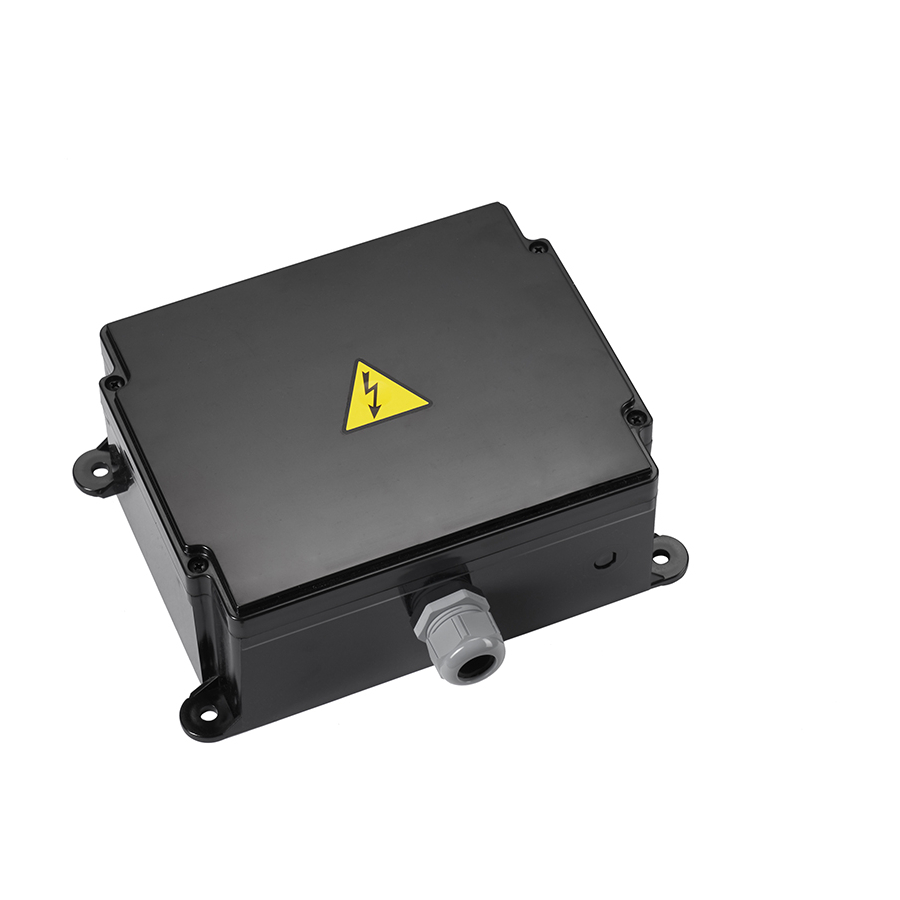
Page 3: Technical Description
02- TECHNICAL DESCRIPTION 1.- Fixing slots (fi xed as- sembly or anti -vibrati on) 2.- M32 Cable Gland 3.- External Antenna A60 (433) or A70 (870) 4.- RS232 / RS485 Socket 5.- Power Supply 6.- INXXX Card Socket 7.- Internal removable EEPROM 8.- TR800-CE MCX Radio 9.- CAN Connecti on... - Page 4 03- RECEIVER’s INSTALLATION WARNING Manage the complete shut down of the machine throughout the whole installati on of the receiver, following the legislati on on occupati onal risk presenti on in force. Check the power supply and shut down the main switch, disconnecti ng the interface cable between the receiver and the machine’s electrical box.
-
Page 5: 04- Troubleshooting
Replace radio switched on: Radio error Blinking if receiving good frames Switched Off and DATA LED If channel not occupied: Check switched On: no valid ID (ikusi chosen ID in the transmitter or system nearby) reset the receiver. GREEN Blinking if a correct ID is received SIGNAL;...
Need help?
Do you have a question about the R70 and is the answer not in the manual?
Questions and answers