Table of Contents
Advertisement
Before operating this product, please read the instructions carefully and save this manual for future use.
Before using this product, be sure to read "Read this first!" (pages 2 to 6).
W0316HM2076 -YI
Operating Instructions
AK-UC3000G
Model No.
AK-UC3000GS
Model No.
Studio Handy Camera
ENGLISH
VQT5M15A-2(E)
Advertisement
Table of Contents

Related Manuals for Panasonic AK-UC3000GS


Summary of Contents for Panasonic AK-UC3000GS
-
Page 1: Operating Instructions
Studio Handy Camera AK-UC3000G Model No. AK-UC3000GS Model No. Before operating this product, please read the instructions carefully and save this manual for future use. Before using this product, be sure to read “Read this first!” (pages 2 to 6). -
Page 2: Read This First
Read this first! Read this first! indicates safety information. CAUTION: CAUTION The optical cable shall remain readily operable. RISK OF ELECTRIC SHOCK DO NOT OPEN To completely disconnect this equipment from the power supply, disconnect the optical cable from the CAUTION: TO REDUCE THE RISK OF ELECTRIC SHOCK, equipment. -
Page 3: Fcc Warning
Read this first! indicates safety information. CAUTION: This product uses a semiconductor laser system and is a Class 1 Laser Product complies with Radiation Performance Standards, 21CFR SUBCHAPTER J. Use of controls or adjustments or performance of procedures other than those specified herein may result in hazardous radiation exposure. -
Page 4: Important Safety Instructions
Read this first! IMPORTANT SAFETY INSTRUCTIONS 1) Read these instructions. 2) Keep these instructions. 3) Heed all warnings. 4) Follow all instructions. 5) Do not use this apparatus near water. 6) Clean only with dry cloth. 7) Do not block any ventilation openings. Install in accordance with the manufacturer’s instructions. 8) Do not install near any heat sources such as radiators, heat registers, stoves, or other apparatus (including amplifiers) that produce heat. - Page 5 4. Connect the apparatus to another power outlet where the power is not shared by any other appliances. AEEE Yönetmeliğine Uygundur. AEEE Complies with Directive of Turkey. Manufactured by: Panasonic Corporation, Osaka, Japan Importer’s name and address of pursuant to EU rules: Panasonic Marketing Europe GmbH...
- Page 6 Read this first! Декларація про Відповідність Вимогам Технічного Регламенту Обмеження Використання деяких Небезпечних Речовин в електричному та електронному обладнанні (затвердженого Постановою №1057 Кабінету Міністрів України) Виріб відповідає вимогам Технічного Регламенту Обмеження Використання деяких Небезпечних Речовин в електричному та електронному обладнанні (ТР ОВНР). Вміст...
- Page 7 f Microsoft , Windows , Windows 7, Windows 8, Windows 8.1, Internet Explorer , ActiveX , and DirectX are either registered trademarks or ® ® ® ® ® ® ® ® trademarks of Microsoft Corporation in the United States and/or other countries. f Apple, Mac, and OS X are trademarks of Apple Inc., registered in the United States and other countries.
-
Page 8: Table Of Contents
Contents Contents Read this first! [Network] screen [Maintenance] screen Chapter 1 Overview Chapter 6 Maintenance Before using the camera Troubleshooting Notes For operations Required environment for computer For IP images Disclaimer Web screen Notes regarding network Checking the operating time SD memory card Warning displays Using the camera in a system... -
Page 9: Chapter 1 Overview
Overview Chapter 1 Before using the camera, read this chapter. -
Page 10: Before Using The Camera
The cooling fan is a consumable supply. Replace it after approximately 50,000 hours of use. Be sure to contact your dealer for the replacement. r Peripheral devices and software f The software of the peripheral devices (CCU and ROP) that are connected to AK-UC3000G/AK-UC3000GS may require upgrading. f For details, contact your dealer. -
Page 11: Notes
OS X 10.8 Safari 6.1.2 Disclaimer In any case, Panasonic will not liable for any of the following: f Incidental, special, or consequential damage or harm caused directly or indirectly in regard to the camera f Trouble or malfunctions caused by the misuse or careless use of a user... -
Page 12: Sd Memory Card
SDXC: 64 GB Visit the support desk available on the following website for the latest information not included in the Operating Instructions. (http://panasonic.biz/sav/pass_e) Observe the following precautions in regard to use and storage of the camera. f Avoid high temperatures and humidity. -
Page 13: Using The Camera In A System
Chapter 1 Overview — Using the camera in a system Using the camera in a system An example of a standard system consisting of the Studio Handy Camera (AK-UC3000G/AK-UC3000GS) and peripheral devices is as follows. For details on the connected devices, refer to the Operating Instructions of each device. -
Page 14: System Block Diagram
Chapter 1 Overview — Using the camera in a system System block diagram (AK-UC3000G/AK-UC3000GS) a: Microphone kit b: 3.45-inch color viewfinder/2-inch HD viewfinder c: Handy lens d: Microphone holder e: 9-inch LCD viewfinder f: Master setup unit g: Camera Control Unit (CCU) -
Page 15: Accessories
Chapter 1 Overview — Accessories Accessories Camera number sheet (1 to 12) Mount cap (already attached to the product) D-sub connector cover (already attached to the product) Camera hanger (x 2) Screw (M3 × 8 mm) (x 4) NOTE t Properly dispose of the packaging materials after unboxing the product. t The camera hangers and screws are used to attach to the Build-up Unit (AK-HBU500G). -
Page 16: Working Frequency Setting
Chapter 1 Overview — Working frequency setting Working frequency setting When the camera is shipped, the working frequency is not set. Before using the camera for the first time, follow the steps below to set the working frequency. SELECT FORMAT TYPE SELECT FORMAT TYPE PLEASE SELECT FORMAT TYPE SET FORMAT TYPE 60Hz? -
Page 17: Chapter 2 Description Of Parts
Description of Parts Chapter 2 This chapter describes the names of the parts, functions, and operations of this camera. -
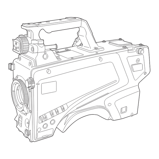
Page 18: Front Side
Chapter 2 Description of Parts — Front side Front side 1 Lens cable/microphone cable clamp Used for securing the lens and microphone cables. 2 Lens mount (Bayonet type) This is where the lens is mounted. 3 <SHUTTER> switch This is the electronic shutter switch. <OFF>: Disables the electronic shutter. -
Page 19: Left Side
Chapter 2 Description of Parts — Left side Left side 12 13 1 <LOCAL> lamp While this lamp is lit, the <ND> filter and <CC> filter can be adjusted manually. 2 <FILTER LOCAL> switch This switch sets whether to adjust the <ND> filter and <CC> filter manually or remotely. 3 <CC>... -
Page 20: Left Side
Chapter 2 Description of Parts — Left side NOTE t Do not remove or insert the card while this lamp is lit. Doing so may damage the SD memory card. 11 SD memory card slot This is the insertion slot for the SD memory card (optional). An SD memory card is used for saving/loading the setting menus of the camera, loading CAC files, updating the software, etc. -
Page 21: Right Side
Chapter 2 Description of Parts — Right side Right side 1 <USB2.0> terminal (host) Used to connect the USB 2.0 cable. NOTE t Use a double-shielded cable when connecting a cable to the <USB2.0> terminal. 2 <OPT FIBER> terminal Used to connect with the CCU using the optical fiber multi cable. When the terminal is not in use, attach the dust cap. 3 <LAN>... -
Page 22: Rear Side
Chapter 2 Description of Parts — Rear side Rear side 6 7 8 12 13 23 24 1 <LIGHT> switch Used to turn the back panel lamp on/off. 2 <PGM1> dial (<INTERCOM1>) Used to adjust the level of the audio or mixing ratio set from [MAIN MENU] → [INTERCOM SETTING] → [LEVEL/PGM1/PGM2 VR SETTING] → [INTERCOM1 PGM1 VR]. - Page 23 Chapter 2 Description of Parts — Rear side 11 <LEVEL> dial (<INTERCOM1>) Used to adjust the volume level of the intercom 1 when the the mixing function of the intercom connected to the <INTERCOM1> terminal and the PGM is enabled. The mixing function of the intercom and the PGM can be enabled/disabled from [MAIN MENU] → [INTERCOM SETTING] → [INTERCOM1] →...
-
Page 24: Rear Side
Chapter 2 Description of Parts — Rear side 30 <TRUNK> terminal This is an input/output terminal for the CCU trunk data (RS-422 × 2 or RS-232C × 2). Set this in [MAIN MENU] → [IN/OUT SELECT] → [TRUNK1]/[TRUNK2]. 31 <G/L IN/PROMPTER OUT> terminal This is the input terminal for genlock signals. -
Page 25: Upper Side
Chapter 2 Description of Parts — Upper side Upper side 1 Viewfinder front/back positioning lever To adjust the front/back position of the viewfinder, loosen this lever and slide the viewfinder forwards or backwards to adjust the viewfinder to a position that enables easy viewing. After adjusting the viewfinder, turn the lever towards <LOCK> to lock the position. 2 Viewfinder left-right positioning ring To adjust the left/right position of the viewfinder, loosen this lever and slide the viewfinder to the left or right to adjust the viewfinder to a position that enables easy viewing. -
Page 26: Bottom Side
Chapter 2 Description of Parts — Bottom side Bottom side 1 Build-up terminal Used to connect the Build-up Unit AK-HBU500G (optional). – 26 –... -
Page 27: Chapter 3 Preparation
Preparation Chapter 3 Follow the procedures described in this chapter to mount the accessories before using the camera. -
Page 28: Attaching The Viewfinder
Chapter 3 Preparation — Attaching the viewfinder Attaching the viewfinder Attach the viewfinder (optional). Attaching the viewfinder HD viewfinder AJ-HVF21KG (optional) can be used with this camera. For details on handling the HD viewfinder, refer to the Operating Instructions of the viewfinder. Viewfinder left-right positioning ring Knob Fig. -
Page 29: Attaching The Rear Viewfinder
Chapter 3 Preparation — Attaching the viewfinder Attaching the rear viewfinder LCD viewfinder AK-HVF100G (optional) can be used with this camera. For details on handling the LCD viewfinder, refer to the Operating Instructions of the viewfinder. Connector cover V-groove Lock release button V-shaped protrusion Fig. -
Page 30: On-Screen Displays Of The Viewfinder
Chapter 3 Preparation — On-screen displays of the viewfinder On-screen displays of the viewfinder Studio Handy Camera settings and messages indicating operating statuses appear on the viewfinder screen. All items that can be displayed are located as follows. 59.94p 1080/59.94p FAN OFF MENU RET1... -
Page 31: On-Screen Displays Of The Viewfinder
Chapter 3 Preparation — On-screen displays of the viewfinder f [R] f [G] f [B] f [Y/C] f [NAM] 9 High-sensitivity mode display Displayed when [MAIN MENU] → [SYSTEM MODE] → [SHOOTING MODE] → [HIGH SENS] is set. 10 Voltage display Indicates the voltage coming in from the power supply. - Page 32 Chapter 3 Preparation — On-screen displays of the viewfinder 20 Chromatic aberration compensation display Displayed when the chromatic aberration compensation function is active. 21 Digital extender display Displayed when the digital extender is being used. 22 Lens extender display Displayed when the lens extender is being used. 23 Iris display Indicates the iris setting value (F value) or [OPEN]/[CLOSE].
-
Page 33: Connecting A Microphone
Chapter 3 Preparation — Connecting a microphone Connecting a microphone When mounting a microphone on the viewfinder (optional) for use A microphone such as microphone kit AJ-MC700P (optional) can be mounted on the viewfinder. Microphone holder Clamp screw Fig. 1 Fig. -
Page 34: When Mounting A Microphone Holder (Optional) For Use
Chapter 3 Preparation — Connecting a microphone When mounting a microphone holder (optional) for use Clamping screw Fig. 1 Fig. 2 Lock lever <MIC 1> terminal Fig. 3 Fig. 4 Remove the screws on the microphone holder mounting position and mount the microphone holder AJ-MH800G (optional). (Fig. Mount the microphone and tighten the clamping screw. -
Page 35: Using External Dc Power Supply
Chapter 3 Preparation — Using external DC power supply Using external DC power supply DC cable External DC power supply <DC IN> terminal Connect the external DC power supply to the <DC IN> terminal on the camera. Turn on the <POWER> switch of the external DC power supply (if the external DC power supply has a <POWER> switch). Set the <POWER>... -
Page 36: Data
CAC file has a name specific to each lens and it can be downloaded from the website. You can check the CAC compatible lenses guaranteed for use with this camera on the Panasonic website. You can also obtain a CAC file from the support desk on the Panasonic website. -
Page 37: Chapter 4 Menu Operations
Menu Operations Chapter 4 This chapter describes how to operate the camera menus and the structure and details of the setting menu. -
Page 38: Menu Operations
Chapter 4 Menu Operations — Menu operations Menu operations Basic operations MAIN MENU (1/2) DISPLAY SETUP SWITCH MODE RETURN SETTING INTERCOM SETTING MIC SETTING PAINT SYSTEM MODE IN/OUT SELECT AUTO SET UP <MENU> button Fig. 1 <SELECT> dial button DISPLAY SETUP DSP SETUP >... -
Page 39: Menu Operations
Chapter 4 Menu Operations — Menu operations Entering characters FILE > SD CARD FILE > SD CARD MODE STORE MODE STORE FILE SEL SCENE FILE SEL SCENE FILE NO. FILE NO. FILE NAME :SCENE1 FILE NAME :SCENE1 SD FILE NO. SD FILE NO. -
Page 40: Menu Configuration
Chapter 4 Menu Operations — Menu configuration Menu configuration [MAIN MENU] [DISPLAY SETUP] Configures the settings for the details to be displayed in the viewfinder. [SWITCH MODE] Configures the function assigned to the switch. [RETURN SETTING] Configures the return switch and return signal name. [INTERCOM SETTING] Configures the details such as gain, etc. -
Page 41: Menu List
Chapter 4 Menu Operations — Menu list Menu list : Can be saved and loaded as a scene file data. : Can be saved and loaded as a user file data. : Can be saved and loaded as an operation file data. [DISPLAY SETUP] [MARKER] Item... -
Page 42: Menu Operations
Chapter 4 Menu Operations — Menu list Item Description of settings [SAFETY MARK2 SWITCH] Shows/hides the safety marker 2. [OFF], [ON] f Factory setting: [OFF] [SAFETY MARK2] Sets the aspect ratio of safety marker 2. [16:9], [15:9], [14:9], [13:9], [4:3] f Factory setting: [4:3] [SAFETY AREA2] Sets the size of safety marker 2. -
Page 43: Menu Operations
Chapter 4 Menu Operations — Menu list Item Description of settings [ZOOM LINK LEVEL] Adjusts the detail level of the zoom-interlocked viewfinder. [1]…[5] f Factory setting: [3] [RETURN SIGNAL] [HD PEAK Adjusts the peak frequency of the return signal. [LOW], [MID], [HIGH] FREQUENCY] f Factory setting: [LOW] [HD OFFSET GAIN]... -
Page 44: Menu Operations
Chapter 4 Menu Operations — Menu list Item Description of settings [SENSOR RATE] Shows/hides the sensor imaging rate display. [OFF], [ON] f Factory setting: [OFF] [VOLTAGE] Shows/hides the power supply display. [OFF], [ON] f Factory setting: [OFF] [SYSTEM MODE] Shows/hides the system frequency/resolution display. [OFF], [ON] f Factory setting: [OFF] [FAN OFF]... -
Page 45: [Switch Mode]
Chapter 4 Menu Operations — Menu list Item Description of settings [FAN OFF] Shows/hides the status display when the fan is off. [OFF], [ON] f Factory setting: [OFF] [MASTER GAIN] Shows/hides the status display when the gain is other than 0 dB. [OFF], [ON] f Factory setting: [OFF] [BLACK GAMMA]... -
Page 46: Menu Operations
Chapter 4 Menu Operations — Menu list [GAIN SETTING] Item Description of settings [LOW GAIN] Sets the amount of gain increase when <L> is selected for the <GAIN> switch. [−6dB]…[36dB] f Factory setting: [0dB] [OFFSET LOW GAIN] Sets the offset from [LOW GAIN]. [−2.9dB]…[+2.9dB] (0.1 dB step) f Factory setting: [0.0dB] [MID GAIN]... -
Page 47: Menu Operations
Chapter 4 Menu Operations — Menu list Item Description of settings [LENS EXT COMP LEVEL] Sets the iris compensation level when lens extender 3 is enabled. [−100]…[+100] f Factory setting: [0] [EXTENDER4] Sets the magnification of lens extender 4. [NONE], [0.1]…[9.9] f Factory setting: [NONE] [LENS EXT COMP LEVEL] Sets the iris compensation level when lens extender 4 is enabled. -
Page 48: Menu Operations
Chapter 4 Menu Operations — Menu list [SHUTTER SELECT] Item Description of settings [SHUTTER OFF BY ROP] Selects whether to enable the shutter mode from ROP. [ENABLE], [DISABLE] f Factory setting: [DISABLE] [POSITION1] Sets the shutter speed of [POSITION1]. [59.94i]/[59.94p] mode: [1/100], [1/120], [1/125], [1/250], [1/500], [1/1000], [1/1500], [1/2000] f Factory setting: [1/100] [50i]/[50p] mode:... -
Page 49: Menu Operations
Chapter 4 Menu Operations — Menu list Item Description of settings [POSITION5] Sets the shutter speed of [POSITION5]. [59.94i]/[59.94p] mode: [1/100], [1/120], [1/125], [1/250], [1/500], [1/1000], [1/1500], [1/2000] f Factory setting: [1/500] [50i]/[50p] mode: [1/60], [1/100], [1/125], [1/250], [1/500], [1/1000], [1/1500], [1/2000] f Factory setting: [1/500] [29.97p] mode: [1/48], [1/50], [1/60], [1/96], [1/100], [1/120], [1/125], [1/250], [1/500], [1/1000], [1/1500], [1/2000]... -
Page 50: [Return Setting]
Chapter 4 Menu Operations — Menu list Item Description of settings [POSITION3] Enables/disables the [POSITION3] settings of the shutter position. [OFF], [ON] f Factory setting: [ON] [POSITION4] Enables/disables the [POSITION4] settings of the shutter position. [OFF], [ON] f Factory setting: [ON] [POSITION5] Enables/disables the [POSITION5] settings of the shutter position. -
Page 51: Menu Operations
Chapter 4 Menu Operations — Menu list Item Description of settings [PGM2 MIX] Sets whether to mix the PGM2 signal with the intercom 1 CH1 output. [OFF], [ON] f Factory setting: [ON] [CRANE INCOM MIX] Sets whether to mix the crane intercom signal with the intercom 1 CH1 output. [OFF], [ON] f Factory setting: [OFF] [INCOM2 MIX]... -
Page 52: Menu Operations
Chapter 4 Menu Operations — Menu list Item Description of settings [PROD MIX] Sets whether to mix the PROD signal with the intercom 2 CH2 output. [OFF], [ON] f Factory setting: [OFF] [PGM1 MIX] Sets whether to mix the PGM1 signal with the intercom 2 CH2 output. [OFF], [ON] f Factory setting: [ON] [PGM2 MIX]... -
Page 53: Menu Operations
Chapter 4 Menu Operations — Menu list Item Description of settings [CANCEL LEVEL] Sets the input/output cancel signal level of Clear-Com. [−20.0dB]…[+20.0dB] (0.5 dB step) f Factory setting: [0.0dB] [SIDE TONE] Sets the side tone volume of Clear-Com. [OFF], [−36dB]…[0dB] (3 dB step) f Factory setting: [−6dB] [CLEAR COM TO CCU] Sets whether to output the Clear-Com audio to the CCU. -
Page 54: [Mic Setting]
Chapter 4 Menu Operations — Menu list Item Description of settings [VR MIN MODE] Sets the level when the volume level is minimum. [MUTE]: Muted [MIN GAIN]: Minimum level f Factory setting: [MUTE] [B/U INTERCOM LEVEL] Sets the audio signal to be controlled by the intercom level of the Build-up Unit. [OFF], [INCOM1], [INCOM2] (for Clear-Com option: [CLEAR COM]), [INCOM1/INCOM2] (for Clear- Com option: [INCOM1/CLEAR COM]) f Factory setting: [OFF]... -
Page 55: Menu Operations
Chapter 4 Menu Operations — Menu list Item Description of settings [BLACK GAMMA] Enables/disables black gamma. [OFF], [ON] f Factory setting: [OFF] [KNEE] Enables/disables knee. [OFF], [ON] f Factory setting: [ON] [WHITE CLIP] Enables/disables white clips. [OFF], [ON] f Factory setting: [ON] [DRS SW] Enables/disables dynamic range stretcher. -
Page 56: Menu Operations
Chapter 4 Menu Operations — Menu list [PEDESTAL] Item Description of settings [MASTER PEDESTAL] Adjusts the black level of the master pedestal. For relative value display: [−99]…[99] For absolute value display: [−2.8%]…[51.3%] f Factory setting: [0]/[0%] [R PEDESTAL] Sets the correction level of red to the master pedestal. [−800]…[+800] f Factory setting: [0] [G PEDESTAL]... -
Page 57: Menu Operations
Chapter 4 Menu Operations — Menu list Item Description of settings [COLOR TEMP BCH] Sets the color temperature when the <WHITE BAL> switch is <B>. When the <CC> filter is set to <B><3200K>: [2000K]…[15000K] When the <CC> filter is set to <C><4300K>: [2300K]…[99999K] When the <CC>... -
Page 58: Menu Operations
Chapter 4 Menu Operations — Menu list Item Description of settings [GAIN OFFSET BCH] Sets whether to maintain the Rch, Gch, and Bch gain levels when adjusting the automatic white balance. [ON]: Maintains the values set in [R GAIN BCH], [G GAIN BCH], and [B GAIN BCH]. [OFF]: Sets [R GAIN BCH], [G GAIN BCH], and [B GAIN BCH] to [0]. -
Page 59: Menu Operations
Chapter 4 Menu Operations — Menu list [GAMMA/BLACK GAMMA] Item Description of settings [GAMMA] Enables/disables gamma correction. [OFF], [ON] f Factory setting: [ON] [GAMMA MODE SELECT] Selects the type of gamma. [HD], [FILMLIKE1], [FILMLIKE2], [FILMLIKE3], [FILM REC], [VIDEO REC] f Factory setting: [HD] [MASTER GAMMA] Adjusts the gamma characteristic. - Page 60 Chapter 4 Menu Operations — Menu list Item Description of settings [KNEE B SLOPE] Adjusts the knee slope of blue to [KNEE MASTER SLOPE]. [−99]…[+99] f Factory setting: [0] [WHITE CLIP] Item Description of settings [WHITE CLIP] Enables/disables the white clip function. [OFF], [ON] f Factory setting: [ON] [MASTER WHITE CLIP LEVEL]...
-
Page 61: Menu Operations
Chapter 4 Menu Operations — Menu list Item Description of settings [DETAIL GAIN(−)] Sets the detail level in the − (downward) direction. [−31]…[+31] f Factory setting: [0] [DETAIL CLIP+] Adjust the detail clip to reduce glare produced by an excess of details. [00]…[63] f Factory setting: [0] [DETAIL CLIP−]... -
Page 62: Menu Operations
Chapter 4 Menu Operations — Menu list Item Description of settings [Q WIDTH] Sets the width of the area where the skin tone effect is applied on the Q axis with [I CENTER] being the center. [0]…[255] f Factory setting: [28] [Q PHASE] Sets the phase of the area where the skin tone effect is applied with the Q axis being the reference. -
Page 63: Menu Operations
Chapter 4 Menu Operations — Menu list Item Description of settings [MATRIX (B-G)_P] Adjusts the linear matrix between blue and green. This item is not available when [MATRIX] is set to [OFF]. [−31]…[+31] f Factory setting: [0] [COLOR CORRECTION] Item Description of settings [PRESET MATRIX] Sets the preset matrix. -
Page 64: Menu Operations
Chapter 4 Menu Operations — Menu list Item Description of settings [B PHASE] Adjusts blue hue. [−127]…[+127] f Factory setting: [0] [B_MG PHASE] Adjusts the hue between blue and magenta. [−127]…[+127] f Factory setting: [0] [MG_PHASE] Adjusts magenta hue. [−127]…[+127] f Factory setting: [0] [MG_R PHASE] Adjusts the hue between magenta and red. -
Page 65: [System Mode]
Chapter 4 Menu Operations — Menu list Item Description of settings [FILE NO.] Selects a file number. When [MODE] is [LOAD]: [OFF], [1]…[8] When [MODE] is [STORE]: [1]…[8] f Factory setting: [1] [FILE NAME] Enters a file name. (15 characters or less) f Factory setting: [SCENE1] [EXECUTE] Selects whether to execute with the configured settings. -
Page 66: [Auto Set Up]
Chapter 4 Menu Operations — Menu list Item Description of settings [HD-SDI2 OUTPUT ITEM] Selects details of the characters superimposed on images output from the <HD SDI2> terminal. [MENU ONLY]: Displays only on the menu. [STATUS]: Displays all characters that are the same as in the viewfinder display. f Factory setting: [MENU ONLY] [HD-SDI2 CHAR] Sets whether to superimpose characters on images output from the <HD SDI2>... -
Page 67: [File]
Chapter 4 Menu Operations — Menu list Item Description of settings [IP ADDRESS] Sets the IP address. f Factory setting: [192.168.0.30] [SUBNET MASK] Sets the subnet mask. f Factory setting: [255.255.255.0] [DEFAULT GATEWAY] Sets the default gateway. f Factory setting: [192.168.0.1] [HTTP PORT] Sets the port number of HTTP (port number when accessing with a browser). -
Page 68: [Maintenance]
Chapter 4 Menu Operations — Menu list Item Description of settings [FILE NAME] Enters a file name. (15 characters or less) f Factory setting: [USER1] [EXECUTE] Selects whether to execute with the configured settings. [NO], [YES] [CAC FILE] [CAC FILE] cannot be selected right after the power is turned on, because boot of the camera is in progress. This is not an error. -
Page 69: Menu Operations
Chapter 4 Menu Operations — Menu list Item Description of settings [W H SAW G] Adjusts Gch white shading for the data selected in [FILE NO.] horizontally using a saw-toothed waveform. [−100]…[+100] f Factory setting: [0] [W H SAW B] Adjusts Bch white shading for the data selected in [FILE NO.] horizontally using a saw-toothed waveform. -
Page 70: Menu Operations
Chapter 4 Menu Operations — Menu list [B/U LIGHT ADJUST] Item Description of settings [BOX SW(PUSH SW)] Sets the luminance of the box switch of the Build-up Unit. [1]…[10] f Factory setting: [5] [LED(POWER)] Sets the luminance of the lamp (<POWER>) of the Build-up Unit. [1]…[10] f Factory setting: [5] [LED(ND/CC)]... -
Page 71: [Diagnostic]
Chapter 4 Menu Operations — Menu list [DIAGNOSTIC] [VERSION] Item Description of settings [CAM MAIN] Displays the software version of the camera. [NETWORK] Displays the version of the network software. [ROM TABLE] Displays the version of the camera table. [CAM FPGA] Displays the FPGA version of the camera. -
Page 72: Chapter 5 Web Screen
Web Screen Chapter 5 This chapter describes how to configure the settings from a computer. -
Page 73: Setting The Network
To install the software, download EASY IP Setup Software (EasyIPSetup.exe) and the installer for the plugin software for the display (nwcv4SSetup.exe) from the following website. (Windows) http://pro-av.panasonic.net/ r EASY IP Setup Software (EasyIPSetup.exe) This software is used for configuring the network settings of the camera. (page 73) r Installer for the plugin software for the display (nwcv4SSetup.exe) -
Page 74: Installing The Plugin Software For Display
Chapter 5 Web Screen — Setting the network f After clicking the [Save] button, it will take approximately two minutes to complete configuration of the camera. Disconnecting the AC adaptor or LAN cable before the configuration has been completed will invalidate the settings. In such a case, configure the settings again. -
Page 75: Displaying The Web Screen
Chapter 5 Web Screen — Displaying the web screen Displaying the web screen You can connect the camera to a computer to view IP images of the camera on a web browser or to configure various settings. To connect the camera’s IP control LAN terminal and a computer directly, use a crossover LAN cable. To connect via a switching hub, etc., use a straight-through LAN cable. -
Page 76: Switching [Live]/[Setup] Screens
Chapter 5 Web Screen — Displaying the web screen It is also recommended that the password is changed regularly. t If you attempt to display multiple H.264 videos on a single computer, the IP images may not be displayed depending on the specifications of the computer. -
Page 77: [Live] Screen
Chapter 5 Web Screen — [Live] screen [Live] screen The camera image can be displayed on the computer. The items displayed differ between when [H.264] is selected and when [JPEG] is selected with the [Compression] button. r H.264 r JPEG 1 Main area (IP image display area) (page 77) 2 [Compression] button (page 78) 3 [Stream] button (page 78) - Page 78 Chapter 5 Web Screen — [Live] screen f Depending on the computer being used, the drawing processor (GDI) of the OS may have restrictions and the images may cause tearing (part of images show deviated display) at major changes of shooting scenes. f On a Windows computer, when [H.264 transmission] is set to [On], the H.264 videos or JPEG images are displayed.
- Page 79 Chapter 5 Web Screen — [Live] screen 3 [3] The main area image is displayed as set in [H.264(3)]. (page 83) 4 [4] The main area image is displayed as set in [H.264(4)]. (page 83) In the following cases, the selection status of the [Stream] button returns to the setting in [Stream] for [Initial display settings for "Live" page] in the [Video over IP] tab.
- Page 80 Chapter 5 Web Screen — [Live] screen 1 Full screen display button (left) Displays the images in full screen. When the image in the main area is displayed in a reduced size, pressing this button once displays the image in its actual resolution in the main area.
-
Page 81: [Setup] Screen
Chapter 5 Web Screen — [Setup] screen [Setup] screen Various settings of this camera can be configured. The setup menu is only available to users set as [1. Administrator] in [Access level]. (page 87) Logging in to the [Setup] screen Fig. -
Page 82: [Basic] Screen
Chapter 5 Web Screen — [Setup] screen [Basic] screen Item Description of settings [Camera title] Enter the name of the camera. Clicking the [Set] button displays the entered name on the camera title display area. The factory setting value is the product number of the camera. You can enter 0 to 20 single-byte characters. - Page 83 Chapter 5 Web Screen — [Setup] screen Item Description of settings [Stream] Selects the image to be displayed on the [Live] screen. [H.264(1)]: Displays movie (H.264 (1)). [H.264(2)]: Displays movie (H.264 (2)). [H.264(3)]: Displays movie (H.264 (3)). [H.264(4)]: Displays movie (H.264 (4)). [JPEG(1)]: Displays still image (JPEG (1)).
- Page 84 Chapter 5 Web Screen — [Setup] screen Item Description of settings [H.264 transmission] Sets whether to transmit H.264 images. [On]: Transmits H.264 images. [Off]: Does not transmit H.264 images. When [H.26 transmission] is set to [On], both H.264 and JPEG images can be displayed on the [Live] screen.
-
Page 85: Setup] Screen
Chapter 5 Web Screen — [Setup] screen Item Description of settings [Control time period] Sets the duration for which the H.264 bitrate is controlled. Images are transmitted so that the average transmission amount in the selected duration will be the bitrate set in [Max bit rate (per client)]. -
Page 86: [User Mng.] Screen
Chapter 5 Web Screen — [Setup] screen Item Description of settings [Unicast port1 (Image)] Sets the unicast port number (to be used when images are transmitted from the camera). This item must be configured when [Transmission type] is set to [Unicast port (MANUAL)]. [1024]…[50000] Only even numbers can be configured. -
Page 87: [Network] Screen
Chapter 5 Web Screen — [Setup] screen Item Description of settings [User name] Enter a user name. Number of characters that can be entered: 1 to 32 Characters that cannot be entered: Double-byte and single-byte symbols " & : ; \ Entering a user name that has been already registered and clicking the [Set] button overwrites the user information. - Page 88 Chapter 5 Web Screen — [Setup] screen [IPv4 network] Item Description of settings [IP address(IPv4)] Enter the IP address of the camera. Enter an IP address that does not conflict with the ones set for computers or other network cameras. f Factory setting: [192.168.0.30] [Subnet mask] Enter the subnet mask of the camera.
-
Page 89: [Maintenance] Screen
Chapter 5 Web Screen — [Setup] screen Item Description of settings [HTTP max segment size (MSS)] Sets whether to limit the maximum segment size (MSS) transmitted from the camera while viewing camera images using HTTP. [Unlimited (1460byte)]: Unlimited (1460 bytes) [Limited (1280byte)]: Limited (1280 bytes) [Limited (1024byte)]: Limited (1024 bytes) It is recommended to set [Unlimited (1460byte)] for normal use. -
Page 90: Chapter
Chapter 5 Web Screen — [Setup] screen Item Description of settings [Model no.] Displays the model number of the camera. [MAC address] Displays the MAC address of the camera. [Firmware version] [CPU Software - CAM MAIN]: Displays the camera’s main software version. [CPU Software - NETWORK]: Displays the software version of the network component. - Page 91 Chapter 5 Web Screen — [Setup] screen Click the [OK] button. Uploading will start. When uploading has finished, a message dialog box appears. Click the [OK] button. The camera will be restarted automatically. – 91 –...
-
Page 92: Chapter 6 Maintenance
Maintenance Chapter 6 This chapter describes the warning displays and after-sales services of the camera. -
Page 93: Troubleshooting
Chapter 6 Maintenance — Troubleshooting Troubleshooting For operations Problem Cause/solution The camera cannot be turned on. Does the power cable plugged into the power outlet securely? The camera cannot be operated from the ROP Is the power turned on? (AK-HRP1000G) that is connected via IP. f If the power lamp of the camera is not lit, the power of the camera is off. -
Page 94: For Ip Images
Chapter 6 Maintenance — Troubleshooting Problem Cause/solution The setting file cannot be downloaded. Is the file download function disabled? (Windows) Perform the following procedure to set. 1) Select [Tools] - [Internet Options] on Internet Explorer. 2) Click the [Security] tab, and then click the [Custom Level…] button on [Security level for this zone]. 3) On the [Security Setting] dialog box, set the [Enable] radio button of [Download file] to on. -
Page 95: Web Screen
Internet Explorer 1) Select [Grant(A)]. 9.0/10.0/11.0. [This webpage wants to run the following add- on: 'WebVideo Module' from 'Panasonic System Networks Co.,Ltd.'.] The information bar indicating the following Perform the following procedure to grant the permission. message appears on Internet Explorer 8.0. -
Page 96: Checking The Operating Time
Chapter 6 Maintenance — Checking the operating time Checking the operating time The operating time can be checked in [MAIN MENU] → [DIAGNOSTIC] → [HOUR METER]. [HEAD]: The operating time of the camera head can be checked. – 96 –... -
Page 97: Warning Displays
Chapter 6 Maintenance — Warning displays Warning displays Warning displays appear when errors have occurred in camera’s auto functions. Camera warning displays r When AWB (automatic white balance) is executed [AWB BREAK] Automatic white balance has been interrupted. [AWB HIGH LIGHT NG] Automatic white balance cannot be executed because the light amount is excessive. -
Page 98: Other Warning Displays
Chapter 6 Maintenance — Warning displays [ASU NG] An error in master pedestal has occurred. [ABB MPED NG] Check the master pedestal settings of automatic black balance. [ASU NOT RUNNING(BAR)] Automatic setup is prohibited. [ASU NOT RUNNING(TEST)] Automatic setup is prohibited. [ASU NOT RUNNING(D.EXT)] Automatic setup is prohibited. -
Page 99: Updating The Camera Firmware
Chapter 6 Maintenance — Updating the camera firmware Updating the camera firmware Refer to the following website for new updates of the firmware and for operating instructions. http://pro-av.panasonic.net/ – 99 –... -
Page 100: Chapter 7 Specifications
Specifications Chapter 7 This chapter describes the specifications of this product. -
Page 101: Specifications
Chapter 7 Specifications — Specifications Specifications Dimensions 151 mm (5-31/32 inches) 371.5 mm (14-21/32 inches) Specifications General Power DC e 12 V (when using an external power supply) AC d 240 V, 50 Hz/60 Hz (when AK-UCU500P/AK-UCU500PS/AK-UCU500E/AK-UCU500ES is connected) Power consumption 119 W (maximum, when connecting to an external 12 V and including supply to an externally connected devices) 360 W (maximum, when AK-UCU500P/AK-UCU500PS/AK-UCU500E/AK-UCU500ES is conncected and including supply to an externally connected devices) indicates safety information. - Page 102 Chapter 7 Specifications — Specifications Dimensions (W×H×D) Body only 151 mm × 267 mm × 371.5 mm (5-31/32 inches × 10-17/32 inches × 14-21/32 inches) (excluding protrusions) Camera unit Pickup device 11 million pixels, CMOS × 1 Optical filter CC: 3200 K, 4300 K, 6300 K, Cross, Diffusion ND: CAP, Clear, 1/4, 1/16, 1/64 Lens mount 2/3-type bayonet...
- Page 103 Chapter 7 Specifications — Specifications <LENS> terminal 12-pin × 1 <VF> terminal 20-pin × 1 <VF> terminal (rear) 29-pin × 1 <DC IN> terminal XLR × 1, 4-pin, DC 12 V <DC OUT 12V 1A> terminal 4-pin × 1 <RET CTRL> terminal 6-pin ×...
-
Page 104: Details Of The Connector Signals
Chapter 7 Specifications — Details of the connector signals Details of the connector signals OPT FIBER OPT-TX(Mark Band=IN) OPT-RX(Mark Band=OUT) AC240V(C) AC240V(H) STBY-SIG STBY-CONT TAJIMI ELECTRONICS OPT-TX(Mark Band=IN) OPT-RX(Mark Band=OUT) STBY-SIG STBY-CONT AC240V(C) AC240V(H) LEMO INTERCOM TALK GND TALK RECEIVE GND RECEIVE CH1 RECEIVE CH2 HA16PRH-5S (Hirose Electric Co.) - Page 105 Chapter 7 Specifications — Details of the connector signals EXT IO CRANE DATA(H) CRANE DATA(C) CRANE CONT(H) 1 2 3 4 CRANE CONT(C) 7 8 9 10 13 14 15 16 CRANE INTERCOM RECEIVE 17 18 19 20 CRANE INTERCOM RECEIVE GND CRANE INTERCOM TALK CRANE INTERCOM TALK GND CRANE PGM1 LEVEL...
- Page 106 Chapter 7 Specifications — Details of the connector signals EARPHONE — AUDIO OUT1 AUDIO OUT2 TRUNK CMD OUT0(H) CMD OUT0(C) CMD IN0(H) CMD IN0(C) CMD OUT1(H) CMD OUT1(C) CMD IN1(H) CMD IN1(C) Not used Not used Not used HR10A-10R-12SC (Hirose Electric Co.) LENS RET-SW IRIS-AUTO...
- Page 107 VF-Y-OUT-GND CAM DATA CAM CONT Not used AC(H) Not used IRIS POS IRIS CNT FOCUS POS/L2C DATA C2L DATA BU ACT Not used AC(C) QR/P8-20S-C (Hirose Electric Co.) DC OUT 2.5A UNREG +12V UNREG GND VJS4444 (Panasonic) – 107 –...
-
Page 108: Index
Index Index [AUTO SET UP] CAC file Connector signal DC power supply [DIAGNOSTIC] [DISPLAY SETUP] Environment for computer External DC power supply External power supply [FILE] [IN/OUT SELECT] [INTERCOM SETTING] [Live] screen [MAINTENANCE] Menu Configuration Operations Microphone Attaching to the microphone holder Attaching to the viewfinder [MIC SETTING] Network settings... - Page 109 Note for the battery symbol (bottom symbol): This symbol might be used in combination with a chemical symbol. In this case it complies with the requirement set by the Directive for the chemical involved. Web Site: http://www.panasonic.com © Panasonic Corporation 2016...
Need help?
Do you have a question about the AK-UC3000GS and is the answer not in the manual?
Questions and answers