Table of Contents
Advertisement
Quick Links
See also:
User Manual
SERVICE MANUAL
Warning
The technical information and parts shown in this
manual are not to be used for: the development,
design, production, storage or use of nuclear, chemical,
biological or missile weapons or other weapons of
mass destruction; or military purposes; or purposes that
endanger global safety and peace. Moreover, do not
sell, give, or export these items, or grant permission for
use to parties with such objectives. Forward all inquiries
to Hitachi Ltd.
Be sure to read this manual before servicing. To assure safety from fi re, electric shock, injury, harmful
radiation and materials, various measures are provided in this Hitachi Multimedia LCD Projector.
Be sure to read cautionary items described in the manual to maintain safety before servicing.
1. When replacing the lamp, avoid burns to your fi ngers, the lamp becomes very hot.
2. Never touch the lamp bulb with a fi nger or anything else. Never drop it or give it a shock. They may
cause bursting of the bulb.
3. This projector is provided with a high voltage circuit for the lamp. Do not touch the electric parts of
the power unit (circuit) or the power unit (ballast) after turning on the projector.
4. Do not touch the exhaust fan during operation.
5. The LCD module assembly is likely to be damaged. If replacing the LCD LENS/PRISM assembly,
do not hold the FPC of the LCD module assembly.
6. Use the cables which are included with the projector or as specifi ed.
1. Features ------------------------------------------------------ 2
2. Specifi cations ----------------------------------------------- 2
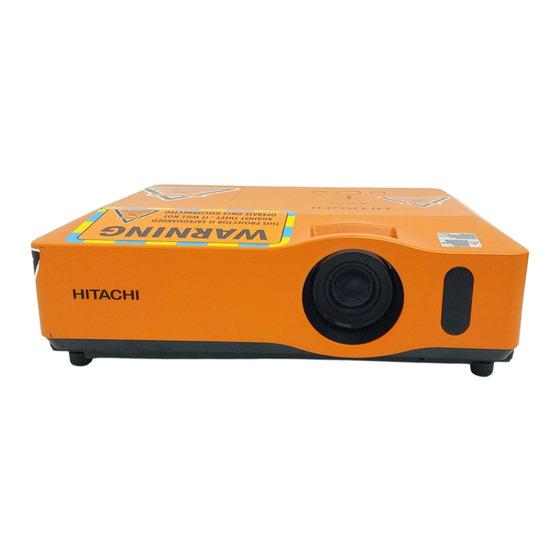
3. Names of each part---------------------------------------- 4
4. Adjustment---------------------------------------------------7
5. Troubleshooting ------------------------------------------ 14
6. Service points --------------------------------------------- 19
7. Wiring diagram-------------------------------------------- 34
SPECIFICATIONS AND PARTS ARE SUBJECT TO CHANGE FOR IMPROVEMENT.
Multimedia LCD Projector
Caution
Service Warning
Contents
8. Disassembly diagram ----------------------------------- 43
9. Replacement parts list ---------------------------------- 51
10. RS-232C communication ------------------------------ 52
11. Block diagram--------------------------------------------- 72
12. Connector connection diagram ----------------------- 73
13. Basic circuit diagram ------------------------------------ 74
March 2008
SM0313
ED-X31EP(C14B-20)
ED-X33EP(C14B-20)
ED-X31GEP(C14D-20)
ED-X33GEP(C14D-20)
Advertisement
Table of Contents

Related Manuals for Hitachi ED-X31EP


Summary of Contents for Hitachi ED-X31EP
-
Page 1: Table Of Contents
Be sure to read this manual before servicing. To assure safety from fi re, electric shock, injury, harmful radiation and materials, various measures are provided in this Hitachi Multimedia LCD Projector. Be sure to read cautionary items described in the manual to maintain safety before servicing. -
Page 2: Features
ED-X31E / ED-X33E (C14B-20) 1. Features • High Brightness • Rich Connectivity • Low Noise • Powerful Sound 2. Specifications Drive system TFT active matrix Liquid crystal Panel size 1.6cm(0.63 type) panel Number of pixels 1024 (H) x 768 (V) Lamp 220W UHB Video : Analog 0.7Vp-p(75 termination) - Page 3 ED-X31GE / ED-X33GE (C14D-20) 1. Features • High Brightness • Rich Connectivity • Low Noise • Powerful Sound 2. Specifications Drive system TFT active matrix Liquid crystal Panel size 1.6cm(0.63 type) panel Number of pixels 1024 (H) x 768 (V) Lamp 230W UHB Video : Analog 0.7Vp-p(75 termination)
-
Page 4: Names Of Each Part
ED-X31E / ED-X33E (C14B-20) 3. Names of each part Projector HOT! (2) (3) (1) Lamp cover The lamp unit is inside. (2) Focus ring (3) Zoom ring (4) Control panel (11) (5) Elevator buttons (x 2) (10) (6) Elevator feet (x 2) (7) Remote sensor (8) Lens (9) Lens cover... -
Page 5: Control Panel
ED-X31E / ED-X33E (C14B-20) Control panel (1) STANDBY/ON button (2) INPUT button (3) MENU button It consists of four cursor buttons. (4) POWER indicator (5) TEMP indicator (6) LAMP indicator Rear panel (1) AUDIO IN1 port (8) CONTROL port (2) AUDIO IN2 port (9) USB port (3) AUDIO OUT port (10) COMPONENT... - Page 6 ED-X31E / ED-X33E (C14B-20) Remote control (1) VIDEO button (10) (2) COMPUTER button (3) SEARCH button MY SOURCE/ VIDEO COMPUTER DOC.CAMERA (4) STANDBY/ON button ASPECT AUTO SEARCH BLANK (5) ASPECT button (16) (12) MAGNIFY FREEZE PAGE VOLUME (6) AUTO button (14) DOWN (11)
-
Page 7: Adjustment
ED-X31E / ED-X33E (C14B-20) 4. Adjustment 4-1 Before adjusting 4-1-1 Selection of adjustment When any parts in the table 4-1 are changed, choose the proper adjusting items with the chart. Table 4-1: Relation between the replaced part and adjustment Adjustment Replaced White Color... - Page 8 ED-X31E / ED-X33E (C14B-20) 4-2 Flicker adjustment (V.COM adjustment) Adjustment procedure Test pattern for the adjustment 1. Use DAC-P - V.COM - R: in the FACTORY MENU to adjust so that the flicker at the center of the screen is less than the flicker at the periphery. (When the flicker is about the same across the whole screen, adjust so that the flicker at the center 128/255...
- Page 9 ED-X31E / ED-X33E (C14B-20) 4-5 E-POS adjustment (vertical bars adjustment 2) Test pattern for the adjustment Adjustment procedure 1. Make this adjustment after completing the ad- justment in the section 4-4. 2. Use DAC -P - E-POS - R in the FACTORY MENU and use it so that vertical bars are minimized.
- Page 10 ED-X31E / ED-X33E (C14B-20) 4-7 Color uniformity adjustments Preparations 1. Perform these adjustments after the adjustments 5. Adjustment point No.1 should not be adjusted, described in the section 4-6. because it controls the brightness of the entire 2. Make a color uniformity adjustments for the fol- screen.
- Page 11 ED-X31E / ED-X33E (C14B-20) Adjustment procedure 1 Note: Since excessive correction may lead to a (When a color differential meter is used) correction data overview during internal 1. First adjust the [MID-1] tone [G:]. calculations, use the following values for 2.
- Page 12 ED-X31E / ED-X33E (C14B-20) Adjustment procedure 2 (visual inspection) same color as measurement point [No.1]. 1. First adjust [MIN] tone [G:]. Adjustment technique: 2. Select [No.2] [G:]. First, adjust [B:] of the point whose color is to If the background is [G] monochrome, press the be adjusted so that it approximates that of [ENTER] key on the remote control to switch to [No.1].
- Page 13 ED-X31E / ED-X33E (C14B-20) Zoom ring 4-8 Adjusting the zoom and focus Focus ring 1. Use the zoom ring to adjust the screen size. 2. Use the focus ring to focus the picture.
- Page 15 ED-X31E / ED-X33E (C14B-20) Power can not be turned on *: Be sure to unplug the power cord before measuring resistance. voltage supplied at pins (8) Measure resistance* and (13) of E800 on the PWB between pins (8) and (13) of PWB assembly MAIN assembly MAIN in standby E800.
- Page 16 ED-X31E / ED-X33E (C14B-20) Lamp does not light *: Be sure to unplug the power cord before measuring resistance. What is the state of Light LAMP indicator DK03 during operation? Is the LAMP installation install the Lamp correct? Not light Is the voltage at “L”...
- Page 17 ED-X31E / ED-X33E (C14B-20) Picture is not displayed when the RGB signal is input Confirm the splash screen the LCD Panels CPC40 connector and the user menu displayed connection to the MAIN correctly? board. PWB assembly MAIN LCD/Lens prism assembly Is the picture from RGB out port displayed correctly...
- Page 18 ED-X31E / ED-X33E (C14B-20) No sound Check at operating mode (Make sure the state of MUTE , Volume and AUDIO-SPEAKER) Disconnect the speaker from the infinity PWB assembly Main and Speaker measure its resistance. about 8 PWB assembly Main PWB assembly INPUT Can not control to RS-232C The check after parts change 1.
-
Page 19: Service Points
ED-X31E / ED-X33E (C14B-20) 6. Service points 6-1 Lead free solder [CAUTION] This product uses lead free solder (unleaded) to help preserve the environment. Please read these instructions before attempting any soldering work. CAUTION Always wear safety glasses to prevent fumes or molten solder from getting into the eyes. Lead free solder can splatter at high temperatures (600˚C). - Page 20 Therefore, regarding these parts, you can either replace part, LCD/Lens prism assembly, or send the whole unit LCD/Lens prism assembly back to HITACHI, where we will replace the malfunctioning part, recondition the device and send it back to you.
- Page 21 ED-X31E / ED-X33E (C14B-20) (3) Disconnect the LCD panel flexible cables and unscrew PWB assembly MAIN to make it free. Remove these screws Flexible cables of LCD panel Flexible cables of LCD panel WARNING Never put the heavy stress to the main board. Otherwise, connectors will be damaged.
- Page 22 ED-X31E / ED-X33E (C14B-20) 3. Maintenance point Actual formation Each color part has same construction.By using swab and air duster, you can easily remove dust from panel and optical filter. 4. Cleaning the panels and optical filters (1) Turn on the set and lit on the lamp. (2) By using swab and air duster, remove the dust.
- Page 23 • If you observe a leakage of a battery, wipe out the flower and then replace a battery. If the flower adheres your body or clothes, rinse well with water immediately. • Use the batteries included in this product or two new batteries of the specified type: HITACHI MAXELL, part number LR6 or R6P.
-
Page 24: Air Filter
ED-X31E / ED-X33E (C14B-20) 6-5 Air filter WARNING • Before caring, make sure the power switch is off and the power cable is not plugged in, then allow the projector to cool suffi ciently. The care in a high temperature state of the projector could cause an electric shock, a burn and/or malfunction to the projector. - Page 25 ED-X31E / ED-X33E (C14B-20) 6-6 Lamp WARNING HIGH VOLTAGE HIGH TEMPERATURE HIGH PRESSURE The projector uses a high-pressure mercury glass lamp. The lamp can break with a loud bang, or burn out, if jolted or scratched, handled while hot, or worn over time. Note that each lamp has a different life- time, and some may burst or burn out soon after you start using them.
- Page 26 ED-X31E / ED-X33E (C14B-20) Replacing the Lamp A lamp has a fi nite product life. Using the lamp for long periods of time could cause the pictures darker or the color tone poor. Note that each lamp has a different lifetime, and some may burst or burn out soon after being started using.
- Page 27 ED-X31E / ED-X33E (C14B-20) 6-7 Other care WARNING Before caring, make sure the power switch is off and the power cable is not plugged in, and then allow the projector to cool suffi ciently. The care in a high temperature state of the projector could cause a burn and/ or malfunction to the projector.
- Page 28 ED-X31E / ED-X33E (C14B-20) 6-8 Notice of AUTO adjustment Use of AUTO adjustment with the image through RGB input optimizes V_POSI, H_POSI, and H_PHASE automatically. In case that projected image has dark tone around its peripheral, AUTO operation sometimes makes artifacts in the image, shifts capture area and so on.
- Page 29 ED-X31E / ED-X33E (C14B-20) 6-9 How to deactivate the security functions This projector is equipped with security functions. (1)MyScreen PASSWORD The MyScreen PASSWORD function can be used to prohibit access to the MyScreen function and pre- vent the currently registered MyScreen image from being overwritten. (2)PIN LOCK PIN LOCK is a function which prevents the projector from being used unless a registered Code is input.
- Page 30 PIN BOX (ID Inquiring Code) 2. Send HITACHI sales company the Inquiring code (10 digits) to inquire the correct PIN code. 3. With the PIN BOX menu displayed, input the correct PIN code. Enter the correct PIN CODE that HITACHI sales company supplied.
-
Page 31: Caution
ED-X31E / ED-X33E (C14B-20) 6-11 Related Messages When the unit’s power is on, messages such as those shown below may be displayed. When any such message is displayed on the screen, please respond as described below. Although these messages will be automatically disappeared around several minutes, it will be reappeared every time the power is turned on. -
Page 32: Regarding The Indicator Lamps
ED-X31E / ED-X33E (C14B-20) 6-12 Regarding the indicator lamps Lighting and flashing of the POWER indicator, the LAMP indicator, and the TEMP indicator have the meanings as described in the table below. Please respond in accordance with the instructions within the table. POWER LAMP TEMP... - Page 33 Select the lamp alarm level. 3 Level 1 Level None STARTUP TYPE Select the startup screen type. 1 : shows Hitachi Logo 2 : No Hitachi Logo PANEL TIME Use time of LCD panel. Reset the PANEL TIME whenever you changed the LCD/LENS prism assembly panel.
-
Page 34: Wiring Diagram 1
Wiring of the circuit power unit (1) Attach the CNGD1 and the CNGD3 with screw. Area of Importance (2) Connect the TSW after you confirmed the print of the TSW. The operations with this symbol have implications (3) Connect the CNPW. with laws/standards. - Page 35 Preparation of the ballast power unit Wiring after attaching the ballast power unit (1) Connect the CNBAR, the CNPFC and the CNLAP. (1) Style the CNBAR, the CNPFC and the CNLAP. (2) Use Ballast power unit white or white marked CNPFC connector is mounted. (3) Pass CNPFC lead through FEB2, and lock hook completely.
- Page 36 Assembling of the power unit block 2. Assembling of the circuit power unit and ballast power unit. (1) Attach the ballast holder to the circuit power unit drawing out the CNPW. Assemble the ballast holder and the circuit power unit touching the CNPW to The assembly order of the power block the arrow A side wall of the ballast holder.
- Page 37 (1) Style CNBAR to ballast holder rib, and fix with ZTP2. Wiring of the power unit (2) Attach the CNDG1 to a ballast holder boss. • Make sure not to overflow the lead from ballast holder slit. (Otherwise, upper case will pinch the lead.) Style of the power unit assembling •...
- Page 38 (1) Connect Main board and Input board with CNVID and CNAU. Preparation of the main board assembling Refer to following procedure. Insert to main board connector. Wiring of the input board assembling Insert to Input board connector. Attach Input board to I/O metal. I/O metal Input board CNVID...
- Page 39 Preparation of the panel duct (1) Draw out the E1 from the panel duct incision. Style the E1 along the side of panel duct, then fix the E1 with tape. (2) Attach the E2 to the panel duct with screw, then draw out the E2 from panel duct slit. Wiring of the panel duct assembling Make sure not make the excessive length in the panel duct.
- Page 40 (1) Attach the CNGD2. (Attach the lamp house with this screw too.) Attaching the power unit (2) Pass the power fan and the CNBAR through the ballast holder slit. Make sure not make the excessive length at the fan side. (3) Attach the CNLAP to the lamp holder (bottom case).
- Page 41 (1) Pass the CNGD2 between the optics unit attaching boss and the main board attaching boss. Attaching the optics unit Then, attach the optics unit. (2) Style the E1, RG panel fan and lamp fan at the internal than main board attaching boss. Wiring of the optics unit attaching Power CNBAR...
- Page 42 (1) Attach main board after you connected exhaust fan. Attach main board with CNGD2 and CNGD3 by screw. Put CNGD2 under CNGD3. Attaching the main board (2) Connect CNPW. Put TSW and CNGD1 under CNPW. (3) Connect RG panel fan, B panel fan, lamp fan, E1, E2 and CNRM. Put excessive length of each cables into the space between B panel fan and panel duct.
-
Page 43: Disassembly Diagram
ED-X31E / ED-X33E (C14B-20) 8. Disassembly diagram PWB assembly INPUT M4x6 obverse reverse rear M3x8 T3x10... - Page 44 ED-X31E / ED-X33E (C14B-20)
- Page 45 ED-X31E / ED-X33E (C14B-20) Notice 1. Detach and attach the upper case. Follow the procedure below to detach and attach the upper case. When disassembling a. Remove the Lamp door. CAUTION The lamp door must be removed before the upper case when disassembling the machine. If the upper case is detached with the lamp door installed, the MAIN board might be damaged.
- Page 46 ED-X31E / ED-X33E (C14B-20) When assembling a. Tighten 7 screws on the bottom and 2 screws on the rear after attaching the upper case with the lamp door separated. CAUTION These are not screw holes. Do NOT insert a screw or screwdriver into them to avoid damag- ing the inside.
- Page 47 ED-X31E / ED-X33E (C14B-20) 2. Detaching and attaching the Panel Fan Duct assembly When disassembling Remove 1 screws and unhook the panel fan duct assembly as shown in the diagram. T3x12 [above] Release the 5 hooks When assembling (1) Put the thermistor and Air sensor in the correct position on the Panel duct as shown in the diagram. 3.
- Page 48 ED-X31E / ED-X33E (C14B-20) 4. Attaching the power unit FAN. Never attach the FAN to the wrong direction. Refer the stamp on the FAN when you attach the power unit FAN. 5. Attaching the exhaust FAN. Never attach the FAN to the wrong direction. Refer the diagram when you attach the exhaust FAN.
- Page 49 ED-X31E / ED-X33E (C14B-20) 6. Attaching the power unit. Refer the diagram when you attach the power unit. Pull the AC inlet frame to the outside. Then, attach the power unit. Make sure that the bottom case does not come in contact with AC SW. CAUTION Never use the wrong screws.
- Page 50 ED-X31E / ED-X33E (C14B-20) 7. Attaching the Lens prism ASSY. Refer the diagram when you attach the Lens prism ASSY. (2) Attach the LCD prism ASSY inserting the Never touch the LCD to any parts when you top of the Lens to the lens enclosure. attach the LCD prism ASSY.
-
Page 51: Replacement Parts List
ED-X31E / ED-X33E (C14B-20) 9. Replacement Parts list THE UPDATED PARTS LIST FOR THIS MODEL IS AVAILABLE ON ESTA MY SOURCE/ COMPUTER VIDEO DOC.CAMERA ASPECT AUTO SEARCH BLANK MAGNIFY FREEZE PAGE VOLUME Power Cord RGB Cable DOWN KEYSTONE MY BUTTON MUTE POSITION MENU... -
Page 52: Rs-232C Communication
ED-X31E / ED-X33E (C14B-20) 5. RS-232C communication CONTROL port RS-232C cable (cross) RS-232C port of the projector of the computer - (1) (1) CD RD (2) (2) RD TD (3) (3) TD - (4) (4) DTR GND (5) (5) GND - (6) (6) DSR RTS (7) - Page 53 ED-X31E / ED-X33E (C14B-20) Requesting projector status (Get command) (1) Send the following request code from the PC to the projector. Header + Command data (‘02H’ + ‘00H’ + type (2 bytes) + ‘00H’ + ‘00H’) (2) The projector returns the response code ‘1DH’ + data (2 bytes) to the PC. Changing the projector settings (Set command) (1) Send the following setting code from the PC to the projector.
- Page 54 ED-X31E / ED-X33E (C14B-20) Command Data Names Operation Type Header Action Type Setting Code Power Turn off BE EF 06 00 2A D3 01 00 00 60 00 00 Turn on BE EF 06 00 BA D2 01 00 00 60 01 00 BE EF 06 00...
- Page 55 ED-X31E / ED-X33E (C14B-20) Command Data Names Operation Type Header Action Type Setting Code User Gamma Pattern BE EF 06 00 FB FA 01 00 80 30 00 00 9 steps gray scale BE EF 06 00 6B FB 01 00 80 30 01 00 15 steps gray scale...
- Page 56 ED-X31E / ED-X33E (C14B-20) Command Data Names Operation Type Header Action Type Setting Code COLOR TEMP GAIN B BE EF 06 00 8C F5 02 00 B3 30 00 00 Increment BE EF 06 00 EA F5 04 00 B3 30 00 00 Decrement BE EF...
- Page 57 ED-X31E / ED-X33E (C14B-20) Command Data Names Operation Type Header Action Type Setting Code OVER SCAN BE EF 06 00 91 70 02 00 09 22 00 00 Increment BE EF 06 00 F7 70 04 00 09 22 00 00 Decrement BE EF 06 00...
- Page 58 ED-X31E / ED-X33E (C14B-20) Command Data Names Operation Type Header Action Type Setting Code FRAME LOCK – TURN OFF BE EF 06 00 3B C2 01 00 50 30 00 00 COMPUTER1 TURN ON BE EF 06 00 AB C3 01 00 50 30 01 00...
- Page 59 ED-X31E / ED-X33E (C14B-20) Command Data Names Operation Type Header Action Type Setting Code COMPUTER1 BE EF 06 00 F2 F4 01 00 B5 20 00 00 COMPUTER2 BE EF 06 00 32 F6 01 00 B5 20 04 00 MONITOR OUT - COMPONENT TURN OFF...
- Page 60 ED-X31E / ED-X33E (C14B-20) Command Data Names Operation Type Header Action Type Setting Code AUDIO-S-VIDEO AUDIO1 BE EF 06 00 D6 DD 01 00 32 20 01 00 AUDIO2 BE EF 06 00 26 DD 01 00 32 20 02 00 AUDIO3 BE EF 06 00...
- Page 61 ED-X31E / ED-X33E (C14B-20) Command Data Names Operation Type Header Action Type Setting Code BLANK MyScreen BE EF 06 00 FB CA 01 00 00 30 20 00 ORIGINAL BE EF 06 00 FB E2 01 00 00 30 40 00 BLUE BE EF 06 00...
- Page 62 ED-X31E / ED-X33E (C14B-20) Command Data Names Operation Type Header Action Type Setting Code MY BUTTON-1 BE EF 06 00 3A 33 01 00 00 36 00 00 COMPUTER1 COMPUTER2 BE EF 06 00 FA 31 01 00 00 36 04 00 BE EF 06 00...
- Page 63 ED-X31GE / ED-X33GE (C14D-20) Command Data Names Operation Type Header Action Type Setting Code Power Turn off BE EF 06 00 2A D3 01 00 00 60 00 00 Turn on BE EF 06 00 BA D2 01 00 00 60 01 00 BE EF 06 00...
- Page 64 ED-X31GE / ED-X33GE (C14D-20) Command Data Names Operation Type Header Action Type Setting Code User Gamma Pattern BE EF 06 00 FB FA 01 00 80 30 00 00 9 steps gray scale BE EF 06 00 6B FB 01 00 80 30 01 00 15 steps gray scale...
- Page 65 ED-X31GE / ED-X33GE (C14D-20) Command Data Names Operation Type Header Action Type Setting Code COLOR TEMP GAIN B BE EF 06 00 8C F5 02 00 B3 30 00 00 Increment BE EF 06 00 EA F5 04 00 B3 30 00 00 Decrement BE EF...
- Page 66 ED-X31GE / ED-X33GE (C14D-20) Command Data Names Operation Type Header Action Type Setting Code OVER SCAN BE EF 06 00 91 70 02 00 09 22 00 00 Increment BE EF 06 00 F7 70 04 00 09 22 00 00 Decrement BE EF 06 00...
- Page 67 ED-X31GE / ED-X33GE (C14D-20) Command Data Names Operation Type Header Action Type Setting Code FRAME LOCK – TURN OFF BE EF 06 00 3B C2 01 00 50 30 00 00 COMPUTER1 TURN ON BE EF 06 00 AB C3 01 00 50 30 01 00...
- Page 68 ED-X31GE / ED-X33GE (C14D-20) Command Data Names Operation Type Header Action Type Setting Code MONITOR OUT - COMPUTER1 BE EF 06 00 F2 F4 01 00 B5 20 00 00 COMPONENT COMPUTER2 BE EF 06 00 32 F6 01 00 B5 20 04 00 TURN OFF...
- Page 69 ED-X31GE / ED-X33GE (C14D-20) Command Data Names Operation Type Header Action Type Setting Code AUDIO-S-VIDEO AUDIO1 BE EF 06 00 D6 DD 01 00 32 20 01 00 AUDIO2 BE EF 06 00 26 DD 01 00 32 20 02 00 AUDIO3 BE EF 06 00...
- Page 70 ED-X31GE / ED-X33GE (C14D-20) Command Data Names Operation Type Header Action Type Setting Code MENU POSITION V BE EF 06 00 40 D7 02 00 16 30 00 00 Increment BE EF 06 00 26 D7 04 00 16 30 00 00 Decrement BE EF...
- Page 71 ED-X31GE / ED-X33GE (C14D-20) Command Data Names Operation Type Header Action Type Setting Code MY BUTTON-1 BE EF 06 00 3A 33 01 00 00 36 00 00 COMPUTER1 BE EF 06 00 FA 31 01 00 00 36 04 00 COMPUTER2 COMPONENT BE EF...
-
Page 72: Block Diagram
L3E01060 A/D converter Video decoder L3E07111 PW190 L3E06150... -
Page 73: Connector Connection Diagram
ED-X31E / ED-X33E (C14B-20) 12. Connector connection diagram... -
Page 74: Basic Circuit Diagram
13. Basic Circuit Diagram FRONT-56 FRONT-38 IR02 IR01 KSM-2003LM2EL KSM-2003LM2EL Vout Vout CR04 CR01 100p-C 100p-C 1005 1005 CR05 CR02 1.0/10 1.0/10 APRC03 APRC02 APRC01 APRC04 SM0313 REMOTE PWB ASSEMBLY - SHEET 1 of 1... - Page 75 SM0313 POWER UNIT (BALLAST) - SHEET 1 of 2...
- Page 76 SM0313 POWER UNIT (BALLAST) - SHEET 2 of 2...
- Page 77 SM0313 POWER UNIT (CIRCUIT) - SHEET 1 of 1...
- Page 78 NOTE PARTS MARKED WITH HATCHING EC02 YLC21-3264V APC06 ARE NOT MOUNTED IN THIS MODEL. Audio-R LC04 1608 APC07 APC10 LC08 NFL21SP407X1C3 2125 APC05 Audio-L LC05 APC24 EC07 APC23 ZH-13V 1608 APC09 C-Video LC07 NFL21SP407X1C3 GND1 2125 APC25 Y(S-Video) APC26 APC04 LC03 C-Video NFL21SP407X1C3...
- Page 79 NOTE PARTS MARKED WITH HATCHING ARE NOT MOUNTED IN THIS MODEL. +3.3VPW I201 I201 DIGITAL INPUT PORT PW190B-10L R2G1 PERIPHERALS PW190B-10L 1005 CH0CK IN0CLK IN0CLP E_FILT I201 NC-D13 CH0PE IN0PEN IN0CST HIGH-P DISPLAY PORT PW190B-10L NC-E18 CH0VB IN0VBI R2G2 R2C4 NC-D14 CH0AH IN0AHS...
- Page 80 NOTE PARTS MARKED WITH HATCHING ARE NOT MOUNTED IN THIS MODEL. I201 RESETN PW190B-10L R200 L251 JUMPER R R203 1.0k 1005 1608 AC15 AC15 R217 1005 AE16 AE16 65mA Q201 AF16 AF16 DTC114EUA AC16 2010 AC16 R201 AD15 AD15 EMU-RESET R218 AE15 AE15...
- Page 81 +6.6V +3.3V R394 R395 1005 1005 MOUSE R305 Q391 R393 2SC4617 S309 CPU-RESET 1005 100 1 R303 I301 SKHHLMA010 PWRC RN5VD26C 1005 1005 I392 RESETN TC7SZ32FU R306 Q301 C303 RT1N141U IN_B RC_EN38 0.1/10 1005 1005 I391 RC-38 IN_A JUMPER R TC7SZ08FU (OR) L391...
- Page 82 NOTE PARTS MARKED WITH HATCHING ARE NOT MOUNTED IN THIS MODEL. C826 R822 R823 1000p 1 L812 10k-1% 10k-1% 1005 SGM20F1C104-4A 1005 1005 I801 2125 SI-3010KM C825 0.01/16 1005 R821 15.5V-Panel --> MM1701AHBE 1005 I802 I805 I806 MM1663DHBE MM1663DHBE MM1701CHBE 1.8V-CPU 3.3V-CPU I804...
- Page 83 NOTE PARTS MARKED WITH HATCHING ARE NOT MOUNTED IN THIS MODEL. JUMPER R L401 I401 2518 L3E07111KOA +3.3VP +1.0V VDD10-D13 L402 VDD10-D14 C421 2.2/6.3 VDD10-D15 HRESETO CHHRST 2518 VDD10-E13 VRESETO CHVRST I401 L3E07111KOA VDD10-E14 HPLL CHHPLL C422 0.01/16 VDD10-F17 CLP1 CHCP1 VDD10-F4 CLP2...
- Page 84 NOTE PARTS MARKED WITH HATCHING ARE NOT MOUNTED IN THIS MODEL. C14 R Panel Part +3.3VP +15.5V 0 ohm R 0 ohm R SHCLKR SHCLKR 0 ohm R ENBXR1 ENBXR1 DXOUTR R552 DXOUTR 0 ohm R CLXOUTR P501 CLXOUTR 1005 54104-36HUp DYOUT APR36...
- Page 85 NOTE PARTS MARKED WITH HATCHING ARE NOT MOUNTED IN THIS MODEL. C14 G Panel Part +3.3VP +15.5V 0 ohm R 0 ohm R SHCLKG SHCLKG 0 ohm R ENBXG1 ENBXG1 DXOUTG R652 0 ohm R DXOUTG CLXOUTG P601 CLXOUTG 1005 54104-36HUp DYOUT APG36...
- Page 86 NOTE PARTS MARKED WITH HATCHING ARE NOT MOUNTED IN THIS MODEL. C14 B Panel Part +3.3VP +15.5V 0 ohm R 0 ohm R SHCLKB SHCLKB 0 ohm R ENBXB1 ENBXB1 DXOUTB R752 0 ohm R DXOUTB CLXOUTB P701 CLXOUTB 1005 54104-36HUp DYOUT APB36...
- Page 87 NOTE PARTS MARKED WITH HATCHING ARE NOT MOUNTED IN THIS MODEL. LV01 2518 JUMPER R GND1 CV41 CV46 CV45 0.047/10 0.047/10 0.047/10 1005 +3.3V 1005 1005 DSUB1_B CHB1 DSUB1_G CHG1 DSUB1_R CHR1 DSUB1_H DSUB1_V RV91 75-1% 1 *ES04 ZH-11H 1005 GND1 APW02 APW01...
- Page 88 NOTE PARTS MARKED WITH HATCHING ARE NOT MOUNTED IN THIS MODEL. LS01 RS05 2518 JUMPER R RS06 1005 RS04 GND1 1005 1005 AP1DG QS02 RT1N141U ES01 3114-15FA APCL HS10 SC200JT SYNC AP1V 2125 VCLK HS08 AP1B SC200JT RS23 PLUG AP1H 2125 CS06 10/6.3...
- Page 89 NOTE PARTS MARKED WITH HATCHING ARE NOT MOUNTED IN THIS MODEL. +15.5V ~ +18.9V Sheet 4 A_VCC CA68 Sheet 4 A_GND 47/25 MVK/SKV RA80 A_GND 1005 Sheet 1 SP_OFF RA19 CA71 4.7k Sheet 1 POWER5 RA20 1005 1.0/16 4.7k POWERA 1005 GND1 IA03...
- Page 90 NOTE PARTS MARKED WITH HATCHING ARE NOT MOUNTED IN THIS MODEL. IK21 RRX6000-0702L CK30 12p-C VSS1 /RST 1005 OSC1 PTA0 XK25 6.00MH OSC2 PTA1 RK30 CK31 VREG PTA2 RK35 12p-C 1005 1005 PTA3 1005 PTD0 PTE0/TCLK PTD1 PTE2/TCH1 PTD2 PTA4 PT03 PTA5 PTD4...
- Page 91 ED-X31E / ED-X33E (C14B-20) Basic circuit diagram list PWB assembly REMOTE PWB assembly MAIN 5 POWER UNIT BALLAST 1 PWB assembly MAIN 6 POWER UNIT BALLAST 2 PWB assembly MAIN 7 POWER UNIT CIRCUIT PWB assembly MAIN 8 PWB assembly INPUT PWB assembly MAIN 9 PWB assembly MAIN 10 PWB assembly MAIN 1...
- Page 92 Fax: +46 (0) 8 562 711 13 Tel: +39 02 38073415 Servizio Clienti Email: csgswe@hitachi-eu.com Fax: +39 02 48786381/2 Email: customerservice.italy@hitachi-eu.com HITACHI EUROPE S.A.S HITACHI EUROPE LTD (Norway) AB Lyon Office STRANDVEIEN 18 B.P. 45, 69671 BRON CEDEX 1366 Lysaker FRANCE...
Need help?
Do you have a question about the ED-X31EP and is the answer not in the manual?
Questions and answers