Table of Contents
Advertisement
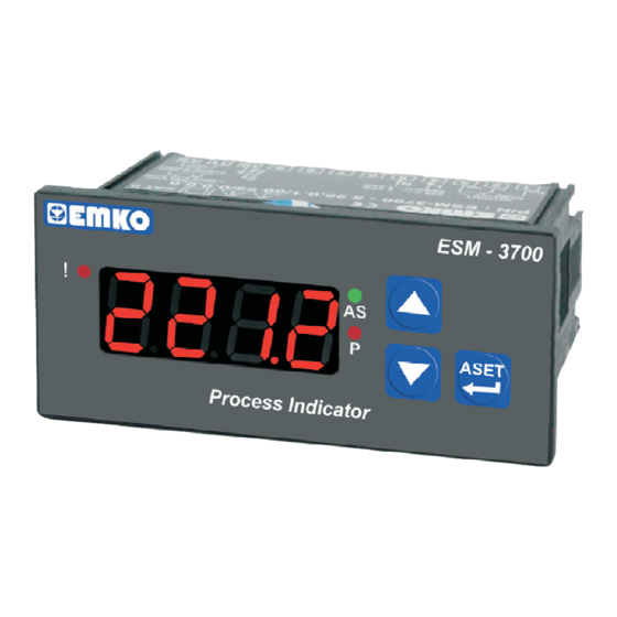
ESM-3700 77 x 35 DIN Size
Digital Process Indicator
- 4 Digits display
- Easily adjustable from front panel
- Configurable display scale between -1999 and 9999
- Adjustable decimal point
- Selectable universal process Input
Z
(0-10 V
, 0-1 V
- Adjustable input filter
- Maximum and minimum measurement value are registered to the
devices memory
- Maximum or minimum measurement value can be shown
continuously on the display
- User can be adjust device's reading value for selected input type
- Alarm output
Relay or SSR driver output (It must be determined in order.)
- Adjustable alarm set value from front panel
- Programming mode password protection
Z
Z
, 0-60 mV
, 0-20 mA
Instruction Manual. ENG ESM-3700 02 V07 05/16
Z
Z
, 4
-20 mA
)
Advertisement
Table of Contents

Related Manuals for EMKO ESM-3700

Summary of Contents for EMKO ESM-3700
- Page 1 - User can be adjust device’s reading value for selected input type - Alarm output Relay or SSR driver output (It must be determined in order.) - Adjustable alarm set value from front panel - Programming mode password protection Instruction Manual. ENG ESM-3700 02 V07 05/16...
- Page 2 ABOUT INSTRUCTION MANUAL Instruction manual of ESM-3700 Digital Process Indicator consists of two main sections. Explanation of these sections are below. Also, there are other sections which include order information and technical specifications of the device. All titles and page numbers in instruction CONTENTS manual are in “...
-
Page 3: Table Of Contents
1.3 WARRANTY 1.4 MAINTENANCE 2.INSTALLATION............................ Page 2.1 GENERAL DESCRIPTION 2.2 FRONT VIEW AND DIMENSIONS OF ESM-3700 DIGITAL PROCESS INDICATOR WITH ALARM OUTPUT 2.3 FRONT VIEW AND DIMENSIONS OF ESM-3700 DIGITAL PROCESS INDICATOR WITHOUT ALARM OUTPUT 2.4 PANEL CUT-OUT 2.5 ENVIRONMENTAL RATINGS 2.6 PANEL MOUNTING... - Page 4 EU DECLARATION OF CONFORMITY Manufacturer’s Name : EMKO ELEKTRONIK A.S. Manufacturer’s Address : DOSAB, Karanfil Sk., No:6, 16369 Bursa, TURKEY The manufacturer hereby declares that the product: Product Name : Digital Process Ýndicator Type Number : ESM-3700 Product Category : Electrical equipment for measurement, control and...
-
Page 5: General Specifications
1.Preface ESM-3700 series Digital Process Indicators are design for measuring the process value. They can be used in many applications with their easy use, alarm output, universal process input properties. Some application fields which they are used are below: Application Fields... -
Page 6: Ordering Information
1.3 Warranty EMKO Elektronik warrants that the equipment delivered is free from defects in material and workmanship. This warranty is provided for a period of two years. The warranty period starts from the delivery date. This warranty is in force if duty and responsibilities which are determined in warranty document and instruction manual performs by the customer completely. -
Page 7: Installation
2.Installation Before beginning installation of this product, please read the instruction manual and warnings below carefully. In package , - One piece unit - Two pieces mounting clamps - One piece instruction manual A visual inspection of this product for possible damage occured during shipment is recommended before installation. -
Page 8: General Description
Mounting Clamp Front Panel IP65 protection NEMA 4X Panel surface (maximum thickness 15 mm / 0.59 inch) 2.2 Front View and Dimensions of ESM-3700 Digital Process Indicator With Alarm Output Maximum 15 mm / 0.59 inch ESM - 3700 ASET Process Indicator 77 mm / 3.03 inch... -
Page 9: Front View And Dimensions Of Esm-3700 Digital Process Indicator Without Alarm Output
2.3 Front View and Dimensions of ESM-3700 Digital Process Indicator Without Alarm Output Maximum 15 mm / 0.59 inch ESM - 3700 Process Indicator 77 mm / 3.03 inch 58,5 mm / 2.30 inch 4 mm / 0.16 inch 2.4 Panel Cut-Out 110 mm / 4.33 inch (min) -
Page 10: Environmental Ratings
2.5 Environmental Ratings Operating Conditions Operating Temperature 0 to 50 °C Max. Operating Humidity : Rh (non-condensing) Altitude Up to 2000 m. Forbidden Conditions: Corrosive atmosphere Explosive atmosphere Home applications (The unit is only for industrial applications) 2.6 Panel Mounting 1-Before mounting the device in your panel, make sure that the cut-out is of the right size. -
Page 11: Installation Fixing Clamp
2.7 Installation Fixing Clamp The unit is designed for panel mounting. 1-Insert the unit in the panel cut-out from the front side. 2- Insert the mounting clamps to the fixing sockets that located left and right sides of device and make the unit completely immobile within the panel Montage of the unit to a system must be done with it’s own fixing clamps. -
Page 12: Electrical Wiring
3.Electrical Wiring You must ensure that the device is correctly configured for your application. Incorrect configuration could result in damage to the process being controlled, and/or personal injury. It is your responsibility, as the installer, to ensure that the configuration is correct. Device parameters has factory default values. -
Page 13: Electrical Wiring Diagram
3.2 Electrical Wiring Diagram Electrical wiring of the device must be the same as ‘Electrical Wiring Diagram’ below to prevent damage to the process being controlled and personnel injury. P/N : ESM-3 CAT II OUTPUT 5 A@250 V V (+) (-) For SSr Output 0 - 20 mA Z 4 - 20 mA Z... -
Page 14: View Of The Device Label
3.3 View of the Device Label Device Label for Universal Process Input, 230V Supply Voltage Input and Alarm Relay Output CAT II P/N:ESM-3700 - 5.20.0.1/00.00/0.0.0.0 Z Voltage Input 0-60mV, 0-1V, 0-10V OUTPUT 230 V ± 15% 5A@250V V Z Current Input 50/60Hz - 1.5VA... -
Page 15: Supply Voltage Input Connection Of The Device
3.4 Supply Voltage Input Connection of the Device Connection of Supply Voltage Input Note-1 External Fuse (1 A T) Power Supply Switch Supply Voltage 230 V (± %15) 50/60 Hz or 115 V (± %15) 50/60 Hz or 24 V (±... -
Page 16: Process Input Connection
3.5 Process Input Connection 3.5.1 Process Input Connection of Serial Transmitter with Current Output (Loop Powered) Transmitter connection by using supply Transmitter connection by using external supply voltage on the device voltage source Transmitter Transmitter mA Z mA Z External Power Supply Note 1... -
Page 17: Process Input Connection Of Transmitter With Voltage Output
For 0...1 V Process Input Input Empedance 11 k For 0...10 V Process Input Galvanic Isolation Test Values of ESM-3 Digital Process Indicator 2000 ESM-3700 .5..00 V ( For ESM-37 .3..) Supply Voltage Ground Input 2000 V V Optional... -
Page 18: Alarm Output Connections
3.7 Alarm Output Connections 3.7.1 Relay Output Connection Device T Fuse Load Fuses must be selected according to the application. 3.7.2 SSR Driver Output Connection Device Last Control Element (SSR) Max. 15 V Max. 28 mA Fuse Load Fuses must be selected according to the application. -
Page 19: Front Panel Definetion And Accessing To The Menus
4. Front Panel Definetion and Accessing to the Menus 4.1 Front Panel Definetion of Device With Alarm Output Led Indication of Alarm Set Value Led Indication of Programming Changing Mode is Active Mode is Active Note-1 It is used to increase the value, in main operation screen show the ESM - 3700... -
Page 20: Observation Of The Software Revision On The Display
4.3 Observation of Software Revision on the Display When power is first applied to the digital process indicator, software revision number is shown on the display. ESM - 3700 ASET Process Indicator “rv” Revision Þ Software revision number ESM - 3700 ASET Process Indicator Main Operation Screen is shown... -
Page 21: Programming Mode Parameter List
4.5. Programming Mode Parameter List Process Input Type Selection Parameter ( Default = 0 ) Process Input type is determined with this parameter. It can be adjusted from 0 to 4 0...10 V ( -1999 ; 9999 ) 0...1 V ( -1999 ;... - Page 22 Low Reading Adjustment Value Parameter ( Default = -1999 ) It defines minimum value for dual point reading adjustment ýt can be adjusted -1999 to ( Up Reading Adjustment Value Parameter( Default = 9999 ) It defines maximum value for dual point reading adjustment ýt can be adjusted ( +1) to 9999 Reading Adjustment Selection Parameter ( Default = 0)
-
Page 23: Operation Graphics Of Alarm Output And Alarm Types
4.6 Operation Graphics of Alarm Output and Alarm Types ( Alarm latching output is selected ) Power Power Time Time Alarm Alarm Status Status Time Time Decrement Alarm Alarm button must be pressed to make Output Output alarm output Active Active is passive Time... -
Page 24: Easy Accessing Diagram Of Programming Mode Parameters
4.7 Easy Accessing Diagram of Programming Mode Parameters 4.7.1 Devices With Alarm Output 5 secs ASET ASET ASET Programming Mode Password Entering Main Operation Screen Entering Screen Screen Enter password with increment and decrement buttons ASET ASET ASET Password Entering Process Input Filter Process Input Type Screen... -
Page 25: Device Without Alarm Output
4.7.2 Devices Without Alarm Output 5 secs ASET ASET ASET Programming Mode Password Entering Main Operation Screen Entering Screen Screen Enter password with increment and decrement buttons ASET ASET ASET Password Entering Process Input Filter Process Input Type Screen Selection Parameter Press ENTER button for Selection Parameter accessing parameter... -
Page 26: Entering To The Programming Mode, Changing And Saving Parameters
4.8 Entering to the Programming Mode, Changing and Saving Parameters Main Operation Screen Programming Screen ASET ASET Programming Mode When ENTER button is pressed Accessing Screen for 5 seconds. “P” led starts to Press increment blink. If programming mode button for accessing entering password is different from to the password 0, programming mode entering... - Page 27 Programming Screen Programming Screen ASET ASET Process Input Type Process Input Filter Selection Parameter Selection Parameter Press increment button for accessing Press ENTER button for accessing to the next parameter to the parameter value. Press ENTER button for accessing to the next parameter ASET ASET...
-
Page 28: Display Functions
5. Display Functions ASET ASET In main operation screen, If increment button is pressed then the maximum measurement value is shown on the display ASET ASET In main operation screen, If decrement button is pressed then the minimum measurement value is shown on the display ASET ASET... -
Page 29: Universal Input User Reading Adjustment Operation
6. Universal Input User Reading Adjustment Operation Programming Screen Main Operation Screen ASET ASET Reading Adjustment Access to the reading adjustment Selection Parameter selection parameter as explained in section 4.7.1 and 4.7.2 Press increment button for accessing to the parameter value. Press ENTER button for accessing to the next parameter ASET... - Page 30 Programming Screen Programming Screen ASET ASET User Reading Adjustment User Reading Adjustment Low Limit Analogue Up Limit Analogue Value Value Parameter Parameter Press ENTER button for Press increment button for accessing to the accessing to the next user reading adjustment up limit analogue parameter value entering screen.
-
Page 31: Failure Messages In Esm 3700 Digital Process Indicator
7. Failure Messages in ESM 3700 Digital Process Indicator If the equivalent voltage or current applied ESM - 3700 to the process input while in parameter user reading adjustment is out of the standard scale, this error message are shown on the display ASET Example-1: Process Indicator... -
Page 32: Specifications
8. Specifications Devices Type : Digital Process Indicator Housing&Mounting : 77 mm x 35 mm x 62.5 mm Plastic housing for panel Mounting. Panel cut-out 71 x 29 mm. Protection Class : NEMA 4X (IP65 at front, IP20 at rear). Weight : Approximately 0.16 Kg. -
Page 33: Other Informations
Emko Elektronik Sanayi ve Ticaret A.Þ. Demirtaþ Organize Sanayi Bölgesi Karanfil Sk. No:6 16369 BURSA/TURKEY Phone : +90 224 261 1900 Fax : +90 224 261 1912 Thank you very much for your preference to use Emko Elektronik Products. Your Technology Partner www.emkoelektronik.com.tr...
Need help?
Do you have a question about the ESM-3700 and is the answer not in the manual?
Questions and answers