Table of Contents
Advertisement
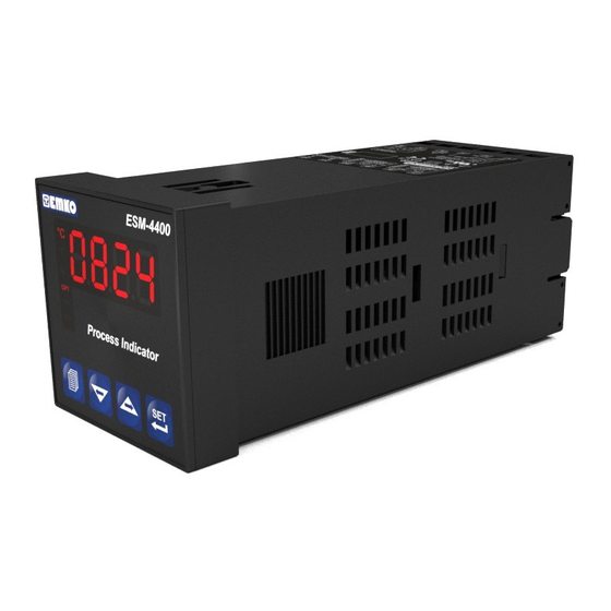
ESM-4400 48 x 48 1/16 DIN
Universal Input Process Indicator with Smart
Output Module System
- 4
digits Process (PV) Display
- Universal Process Input
- Dual or Multi Point Calibration for
- Smart Output Module System
- Programmable Alarm Functions
- Retransmission of Process Value or Process Control by Using
Z
0/4...20 mA
Current Output Module
- Hardware Configuration With Output Modules
- RS-232 (standard) or RS-485 (optional) Serial Communication
With Modbus RTU Protocol
Z
Z
(TC, RTD, mV
, V
Z
V
oltage / Current Input
Instruction Manual. ENG ESM-4400 02 V02 03/05
Z
, mA
)
Advertisement
Table of Contents

Subscribe to Our Youtube Channel
Related Manuals for EMKO ESM-4400


Summary of Contents for EMKO ESM-4400
- Page 1 - Retransmission of Process Value or Process Control by Using 0/4...20 mA Current Output Module - Hardware Configuration With Output Modules - RS-232 (standard) or RS-485 (optional) Serial Communication With Modbus RTU Protocol Instruction Manual. ENG ESM-4400 02 V02 03/05...
- Page 2 ABOUT INSTRUCTION MANUAL Instruction manual of ESM-4400 Process Indicator consists of two main sections. Explanation of these sections are below. Also, there are other sections which include order information and technical specifications of the device. All titles and page numbers in instruction manual are in “...
- Page 3 3.4.4 PROCESS INPUT CONNECTION OF 3-WIRE TRANSMITTERS WITH CURRENT OUTPUT 3.4.5 CONNECTION OF TRANSMITTERS WITH VOLTAGE OUTPUT TO PROCESS INPUT 3.5 RELAY OUTPUT CONNECTION 3.6 GALVANIC ISOLATION TEST VALUES OF ESM-4400 PROCESS INDICATOR AND OUTPUT MODULES 4.DEFINITIONS AND SPECIFICATIONS OF MODULES..............Page 4.1 OUTPUT MODULES 4.1.1 EMO-400 RELAY OUTPUT MODULE...
- Page 4 8.2.1 PROCESS INPUT TYPE AND RELEVANT PARAMETERS WITH PROCESS INPUT 8.2.2 MODULE-1 CONFIGURATION PARAMETERS 8.2.3 MODULE-2 CONFIGURATION PARAMETERS 8.2.4 OUTPUT-3 CONFIGURATION PARAMETERS 8.2.5 GENERAL PARAMETERS 8.2.6 PARAMETERS FOR CONFIGURATION OF SERIAL COMMUNICATION 8.2.7 TECHNICIAN PASSWORD 9.FAILURE MESSAGES IN ESM-4400 PROCESS INDICATORS............Page 10.SPECIFICATIONS..........................Page...
- Page 5 EU DECLARATION OF CONFORMITY Manufacturer Company Name : Emko Elektronik A.S. Manufacturer Company Address: DOSAB, Karanfil Sokak, No:6, 16369 Bursa, Turkiye The manufacturer hereby declares that the product conforms to the following standards and conditions. Product Name : Process Indicator...
-
Page 6: General Specifications
Some application fields which they are used are below: Application Fields Glass Plastic Petro-Chemistry Textile Automative Machine production industries 1.1 General Specifications Standart ESM-4400 Universal Supply Input 100-240 V , 50/60Hz Power Supply Low Voltage (optional) Input Supply Input 50/60Hz, 24V Universal Process Input... -
Page 7: Ordering Information
1.2 Ordering Information All order information of ESM-4400 are BC D FG HI ESM-4400 given on the table at left. User may form (48x48 1/16 DIN) appropriate device configuration from information and codes that at the table and Supply Voltage V 15%;+10%... -
Page 8: Warranty
1.3 Warranty EMKO Elektronik warrants that the equipment delivered is free from defects in material and workmanship. This warranty is provided for a period of two years. The warranty period starts from the delivery date. This warranty is in force if duty and responsibilities which are determined in warranty document and instruction manual performs by the customer completely. - Page 9 2.Installation Before beginning installation of this product, please read the instruction manual and warnings below carefully. In package , - One piece unit - One piece mounting clamp - One piece instruction manual A visual inspection of this product for possible damage occured during shipment is recommended before installation.
-
Page 10: General Description
Panel surface Front Panel (maximum thickness 5mm / 0.2 inch) Ip65 protection NEMA 4X 2.2 Dimensions Maximum 5mm / 0.2 inch ESM-4400 °C °F Process Indicator 48mm / 1.89 inch 11.5 ± 1 mm /0.45 inch 104.5 mm/ 4.11 inch... -
Page 11: Panel Cut-Out
2.3 Panel Cut-Out 65 mm / 2.56 inch (min) 46 mm / 1.81 inch (min) -
Page 12: Environmental Ratings
2.4 Environmental Ratings Operating Conditions Operating Temperature 0 to 50 °C Max. Operating Humidity : Rh (non-condensing) Altitude Up to 2000m. Forbidden Conditions: Corrosive atmosphere Explosive atmosphere Home applications (The unit is only for industrial applications) 2.5 Panel Mounting 1-Before mounting the device in your panel, make sure that the cut-out is of the right size. -
Page 13: Installation Fixing Clamp
2.6 Installation Fixing Clamp The unit is designed for panel mounting. 1-Insert the unit in the panel cut-out from the front side. 2-Insert the mounting clamp from the rear side of the unit and screw up the fixing screws until the unit completely immobile within the panel Montage of the unit to a system must be done with it’s own fixing clamps. -
Page 14: Terminal Layout And Connection Instruction
3.Electrical Wirings You must ensure that the device is correctly configured for your application. Incorrect configuration could result in damage to the process being controlled, and/or personal injury. It is your responsibility, as the installer, to ensure that the configuration is correct. Parameters of the device has factory default values. -
Page 15: Electrical Wiring Diagram
Voltage/Current) Output-3 Standard Relay Output 0 - 50mV 0 - 10V 0 - 20mA Z Pt-100 OUTPUT - 3 5A@250V V P/N : ESM-4400 CAT II Communication Socket MODULE-1 MODULE-2 Supply Voltage Input V 15%;+10% Optional Output Module Terminals 100-240V... -
Page 16: Supply Voltage Input Connection Of The Device
3.3 Supply Voltage Input Connection of the Device Connection of Universal Connection of Low Voltage 24 Connection of Low Voltage Supply Voltage Input Supply Voltage Input Supply Voltage Input Note-2 External Fuse External External (24V : 1 A Fuse Fuse (24V : 1 A (1 A... -
Page 17: Process Input Connection
3.4 Process Input Connection 3.4.1 TC (Thermocouple) Connection Connect the wires with the polarity as shown in the figure left. Always use compensation wire corresponding to the thermocouple used. If present, the shield must be connected to a proper ground. Input resistance is greater than 10M W. -
Page 18: Process Input Connection Of Serial Transmitters With Current
3.4.3 Process Input Connection of Serial Transmitters with Current Output (Loop Powered) Transmitter connection by using supply Transmitter connection by using external supply voltage on the device voltage source. Transmitter Transmitter External Power Supply Note 1 12 V 12 V Max. - Page 19 3.4.5 Connection of Transmitters with Voltage Output to Process Input Transmitter connection by using supply Transmitter connection by using external supply voltage on the device voltage source. mV, VZ mV, VZ External Power Supply Note 1 12 V 12 V Transmitter Transmitter Max.
-
Page 20: Galvanic Isolation Test Values Of Esm-4400 Process Indicator And
3.6 Galvanic Isolation Test Values of ESM-4400 Process Indicator and Output Modules 2000V ( For ESM-4400.1..) ( For ESM-44 0 2 0 ..Supply Input Ground 2000VV 2000VV Output-3 Relay Output 2000VV 2000VV EMO-400 Relay Output Module 2000VV... -
Page 21: Output Modules
4.Definitions and Specifications of Modules ESM-4400 Process Indicator is a modular product which is designed to operate with additional analogue and digital output units which user may need. Two output modules can be plugged in the device by the user. User may configure the product for different applications according to the system requirements with the output modules which are described in this section. -
Page 22: Emo-410 Ssr Driver Output Module
4.1.2 EMO-410 SSR Driver Output Module EMO-410 SSR Driver Output Module can be plugged in Module-1 or Module-2 socket to use functions which are defined for SSR driver output. Specifications of EMO-410 SSR Driver Module Z ±10%, isolated Output Maximum 20 mA, 15-18V Dimensions : 14x30.7x41.4mm Applications of EMO-410 SSR Driver Output Module... -
Page 23: Emo-430 0/4 ...20Ma Current Output Module
4.1.4 EMO-430 0 / 4 ...20mA Current Output Module EMO-430 0/4...20mA Current Output Module can be plugged in Module-1 or Module-2 socket to use functions which are defined for current or voltage output. (It is defined as Analogue Output Module in some sections) Specifications of EMO-430 0/4...20mA Current Output Module Output... - Page 24 4.2 Installing and Pulling Out Input/Output Modules First, detach all cable connections from the device and uninstall it from the panel. Suppress to the lock pins where top and bottom of the device Pull the cover case with your other hand from front panel to rear side.
-
Page 25: To Stick Output Modules' Labels To The Device
4.3 To Stick Output Modules’ Labels to the Device Every module which is plugged in Module-1 or Module-2 socket has labels’ for showing the relation between connection terminal and the device. These labels are attached to empty boxes which are separated for Module-1 and Module-2 on the device. Labels for all modules and attachment places are shown below. - Page 26 : 0/4 to 20mAZ 3A@250V 100 to 240 VV EMO-430 EMO-400 50/60 Hz - 6VA Current Output Relay Output Module Module P/N : ESM-4400 CAT II 0 to 50mV OUTPUT-3 0 to 10V 5A@250VV 0 to 20mAZ Pt-100 PTC, NTC...
-
Page 27: Connection Wirings For Output Modules
5. Connection Terminals of Output Modules and Connection Wirings Module-1 / Module-2 Optional Output Modules EMO-410 EMO-420 EMO-430 EMO-400 Digital Output SSR Driver Current Output Relay Output Module Output Module Module Module 0/4 to 20 mA Z Max. Max. 3A@250V V 20mA@18V Z 40mA@18V Z Module-1 Connection... -
Page 28: Emo-420 Digital (Transistor) Output Module Connection
5.1.3 EMO-420 Digital (Transistor) Output Module Connection Module-1 Module-2 Load Load 15-18 V 15-18 V Maximum 40mA Maximum 40mA 5.1.4 EMO-430 0/4... 20 mA Current Output Module Connection Other Device Module-1 Shunt (Max. 600 ) Module-2 Other Device Shunt (Max. 600 ) 5.1.5 To Get 0...10V with EMO-430 0/4...20 mA Current Output Module... -
Page 29: Cable Connection Between Rs-232 Terminal Of The Device And Pc
6.Connections for RS-232 / RS-485 Serial Communication RS-232 Terminal Definitions RS-485 Terminal Definitions 6.1 Cable Connection Between RS-232 Terminal of the Device and PC ESM-4400 PC (Personal Computer) Cable Lenght must be max. 9 Pin DCON connection 12 meters for 9600 baud... -
Page 30: Connection For Rs-485 Serial Communication
6.2 Connection for RS-485 Serial Communication PC(Personal Computer) RS-232 RS-485 Þ Convertor RS-232 Connection MASTER Cable SLAVE-1 32 terminal can be connected in RS- 485 line Rt resistor = 120 For communication connection Twisted Pair cable must be used Cable lenght can be maximum 1000 meters in 9600 baud rate. -
Page 31: Installing Rs-232 / Rs-485 Serial Communication Modules To The
6.3 Installing RS-232 / RS-485 Serial Communication Modules to the Device Pull the cover case with your hand through rear side as explained in “Installing and Pulling Out Output Modules” section. Pull the modules in Module-1 and Module-2 socket through rear side. Separate supply card which is at the bottom of the equipment by lifting the locking tabs located on front panel. -
Page 32: Definition Of Front Panel
7.Definition of Front Panel and Accessing to the Parameters 7.1 Definition of Front Panel LED indication of °C:Centigrade Unit LED indication of °F Fahrenheit Unit LED indication of units other than °C and °F ESM-4400 LED indication of Output-1 Status Displays °C °F Process Value (PV) -
Page 33: Observation Of Optional Modules And Software Revision On The
Module definiton codes and how to observe these codes of optional modules in Module-1 and Module-2 socket are explained below : ESM-4400 °C °F Revision number “... - Page 34 When power on, display of the indicator is like below: ESM-4400 ESM-4400 ESM-4400 °C °C °C °F °F °F Process Indicator Process Indicator Process Indicator First segments of top and Second segments of top and Third segments of top and bottom displays are tested bottom displays are tested.
- Page 35 7.3 Adjustment of Alarm Set Values If standard output ( Output-3 ) or any output module in Module-1 or Module-2 socket are configured as alarm output, how to access to these alarm set values are explained below: Operation Screen °C °F Process Indicator Press Set button...
- Page 36 Alarm-2 Set value °C °F This parameter is not accessible, if there is a module Process Indicator in Module-2 socket or the module is not an alarm output Press Menu button to exit from Set menu Press Set button to access to the other Set value Press increment °C...
- Page 37 Alarm-3 Set value °C °F This parameter is not accessible, Output-3 is Process Indicator not an Alarm output Press Menu button to exit from Set menu Press Set button to exit from Set menu Press increment °C °F button to see set value Process Indicator Value on the display starts to flash...
-
Page 38: Accessing To The Technician Menu
7.4 Accessing to the Technician Menu The parameters have been divided into groups according to their functions. Every group has a title and firstly user must determine the title (menu) for accessing to the parameters. Refer to the parameters section for detailed information about parameters. Operation Technician °C... - Page 39 Values that out2 CONF Menu °C °C are on the °F °F Configuration left and parameters of output right are module in Module-2 shown on Technician Process Indicator Process Indicator socket the screen can access to for short the former intervals Technician can menu by...
- Page 40 PASS CONF Menu Values Technician Password °C °C that are °F °F This menu is not on the left Technician accessible if and right can access to Technician Process Indicator Process Indicator are shown the former Parameters Section on the menu by is entered by screen for...
-
Page 41: Changing And Saving Parameters
7.5 Changing and Saving Parameters Example-1 : To change Process Input Type parameter in PýnP Conf” menu, user must “ access to PýnP ConF menu firstly. Operation Technician °C °C °C °F °F °F Screen Menu Entering Screen Process Indicator Process Indicator Process Indicator If technician... - Page 42 Value on the display Selection of Process °C °F starts to flash Input Type means, input type is RTD. Process Indicator Parameter can be changed with increment and decrement buttons Value on the display Process Input Type °C °F flashes Selection TC input type is selected Process Indicator...
- Page 43 EXAMPLE-2 : To change Alarm Type parameter “out3 Conf” menu, user must access out3 Conf menu firstly. Operation Technician °C °C °C °F °F °F Screen Menu Entering Screen Process Indicator Process Indicator Process Indicator If technician When Menu button is Press Set button for entering password is not 0, pressed, technician menu...
- Page 44 Values that out2 CONF Menu °C are on the °C °F °F Configuration left and parameters of output right are Technician module in Module-2 shown on can access to Process Indicator Process Indicator socket the screen the former for short menu by Technician can intervals...
- Page 45 Value on the display Alarm Type Selection °C °F flashes Process low alarm Process Indicator Press Set button to confirm the parameter and access to the next parameter Alarm Hysteresis °C °F Selection Process Indicator Press Set button to access to the next parameter Out3 CONF Menu Press Menu button to access to...
- Page 46 Z Voltage/Current Input Calibration Type Example-3 : To change parameter “ PýnP Conf” menu Parameter is on “PýnP ConF” menu. For accessing to this parameter, technician must access to “PýnP ConF” menu firstly. In this example, changing input type of a device from thermocouple to ZVoltage/Current and dual point calibration selection is shown.
- Page 47 Value on the display Process Input Type °C °F starts to flash Selection Process Indicator Parameter can be changed with increment and decrement buttons Process Input Type Selection Value on the display °C °F flashes For accessing to Parameter, parameter Must be .If it is not Process Indicator...
- Page 48 Zvoltage / Current Input Value on the display °C °F starts to flash Calibration Type Selection Process Indicator Parameter can be changed with increment and decrement buttons Zvoltage / Current Input Value on the display °C °F flashes Calibration Type Selection Process Indicator Press Set button to confirm the parameter and access to...
- Page 49 8. Parameters Parameters are divided into two groups. These are Alarm Set and Technician parameters. Technician parameters are grouped into subgroups according to their functions. The subgroups are named as menu pages. 8.1 Alarm SET Parameters If EMO-400 Relay, EMO-410 SSR Driver or EMO-420 Digital (Transistor) output module is plugged in Module-1 socket and output is configured as an alarm output, this parameter defines the set value of the alarm output.
- Page 50 8.2 Technician Parameters 8.2.1 Process Input Type and Relevant Parameters with Process Input Defines the process input type. TC input type selection RTD input type selection ZVoltage/Current input type selection. Defines type and scale of the thermocouple for TC input. It is active if TC input type is selected.
- Page 51 Defines type and scale of sensor for RTD input. It is active if RTD input is selected. Sensor type : PT-100 Scale: -200°C to 650°C (If unit is °C) Scale: -328°F to 1202°F (If unit is °F) Sensor type : PT-100 Scale: -199.9°C to 650.0°C (If unit is °C) Scale: -199.9°F ile 999.9°F (If unit is °F) Defines input range and scale of...
- Page 52 Process Set value Po10 Po11 Po09 Po12 Po08 Po13 Po07 Po14 Po15 Po06 Po16 Po05 Po04 Po03 Po02 Po01 Po00 = 0 3.125 6.25 9.375 12.5 15.625 18.75 21.825 28.125 31.25 34.375 37.5 40.625 43.75 46.875 3.125 3.125 3.125 3.125 3.125 3.125 3.125 3.125 3.125 3.125 3.125 3.125 3.125 3.125 3.125 3.125 0-50 mV range are divided into 16 egual parts.
- Page 53 8.2.2 MODULE-1 Configuration Parameters Module-1 configuration parameters are arranged automatically by the device according to the module type in Module-1 socket. These parameters are not accessible if there is no module in Module-1 socket. It determines logic output function of the output module in Module-1 socket Defines alarm type Alarm-1 hysteresis value...
- Page 54 Process high alarm Alarm Output Alarm Process Value Process low alarm Alarm Output Alarm Process Value Alarm- 1 hysteresis value. It is active if logic output function of Module- 1 is selected alarm output. It can be adjusted from 0% to 50% of process input scale Alarm on delay time.
- Page 55 These parameters are active if EMO-430 (0/4...20 mA Current Output) module is plugged in Module-1 socket. EMO-430 Configuration of analogue output module in Module-1 socket. 0...20mA output or 0...10V according to Section 5.1.5 is selected. 4...20mA output or 2...10V according to Section 5.1.5 is selected.
- Page 56 8.2.3 MODULE-2 Configuration Parameters Module-2 configuration parameters are arranged automatically by the device according to the module type in Module-2 socket. These parameters are not accessible if there is no module in Module-2 socket. It determines logic output function of the output module in Module-2 socket Defines alarm type Alarm-2 hysteresis value...
- Page 57 Process high alarm Alarm Output Alarm Process Value Process low alarm Alarm Output Alarm Process Value Alarm- 2 hysteresis value. It is active if logic output function of Module- 2 is selected alarm output. It can be adjusted from 0% to 50% of process input scale Alarm on delay time.
- Page 58 These parameters are active if EMO-430 (0/4...20 mA Current Output) module is plugged in Module-2 socket. EMO-430 Configuration of analogue output module in Module-2 socket. 0...20mA output or 0...10V according to Section 5.1.5 is selected. 4...20mA output or 2...10V according to Section 5.1.5 is selected.
- Page 59 8.2.4 OUTPUT-3 Configuration Parameters It determines logic output function of Output-3 Alarm output Sensor break alarm output Output is active when the process value is out of the band which is defined with minimum value of operating scale And maximum value of operating scale It determines alarm type.
- Page 60 Alarm off delay time. It can be adjusted from 0000 to 9998 seconds. When the value is greater than 9998, is seen on the display. It means alarm latching output is selected. It is active if logic output function of Output-3 is alarm output. Alarm Status Delay...
- Page 61 8.2.5 General Parameters Minimum value for process set and alarm set values. It is named as low limit of set scale. It can be adjusted from low limit of input selected with parameter parameter. Please refer to Section 8.2.1 Process Input Type and Relevant Parameters with Process Input for parameter Maximum value for process set and alarm set values.
- Page 62 SET button without entering password (For observing parameters) User can see all menus and parameters except Operator and Technician Password menu (“Pass Conf”) but parameters can not be changed. ( Please refer to Section 9. Failure Messages (4) in ESM-4400 Process Indicators )
- Page 63 9. Failure Messages in ESM-4400 Process Indicator 1 - Sensor failure in analogue inputs. Sensor connection is wrong or °C there is no sensor connection. °F Process Indicator 2 - If display blinks : If analogue input value is less than minimum value °C...
- Page 64 4 - If technician password is different °C °C from “0” and user accesses to the °F °F parameter by Set button without entering the technician password and wants to change a parameter, the warning Process Indicator Process Indicator message is shown on the bottom display as shown on the left.
- Page 65 10. Specifications Device Type : Process Indicator Housing&Mounting : 48mm x 48mm x 116mm 1/16 DIN 43700 plastic housing for panel mounting. Panel cut-out is 46x46mm. Protection Class : NEMA 4X (Ip65 at front, IP20 at rear). Weight : Approximately 0.21 Kg. Environmental Ratings : Standard, indoor at an altitude of less than 2000 meters with none condensing humidity.
Need help?
Do you have a question about the ESM-4400 and is the answer not in the manual?
Questions and answers