Table of Contents
Advertisement
Quick Links
High Definition Video Camera
HDC-SX5P
Model No.
HDC-SX5PC
HDC-SX5EG
HDC-SX5E
HDC-SX5EB
HDC-SX5EP
HDC-SX5EE
HDC-SX5GC
HDC-SX5GCS
HDC-SX5GN
HDC-SX5SG
HDC-SX5PL
HDC-SX5GK
VOL.1
Colour
(S)....................Silver Type
© 2007 Matsushita Electric Industrial Co., Ltd. All
rights reserved. Unauthorized copying and distribu-
tion is a violation of law.
ORDER NO.VM0708044CE
B17
Advertisement
Chapters
Table of Contents

Subscribe to Our Youtube Channel
Related Manuals for Panasonic HDC-SX5P


Summary of Contents for Panasonic HDC-SX5P
- Page 1 ORDER NO.VM0708044CE High Definition Video Camera HDC-SX5P Model No. HDC-SX5PC HDC-SX5EG HDC-SX5E HDC-SX5EB HDC-SX5EP HDC-SX5EE HDC-SX5GC HDC-SX5GCS HDC-SX5GN HDC-SX5SG HDC-SX5PL HDC-SX5GK VOL.1 Colour (S)....Silver Type © 2007 Matsushita Electric Industrial Co., Ltd. All rights reserved. Unauthorized copying and distribu- tion is a violation of law.
-
Page 2: Table Of Contents
TABLE OF CONTENTS PAGE PAGE 1 Safety Precaution -------------------------------------------------3 1.1. General Guidelines ----------------------------------------3 2 Warning --------------------------------------------------------------4 2.1. Prevention of Electrostatic Discharge (ESD) to Electrostatic Sensitive (ES) Devices ---------------4 2.2. Caution for AC Cord (VJA0940 type) -----------------5 2.3. Service caution based on legal restrictions----------6 2.4. -
Page 3: Safety Precaution
1 Safety Precaution 1.1. General Guidelines 1. IMPORTANT SAFETY NOTICE There are special components used in this equipment which are important for safety. These parts are marked by in the Schematic Diagrams, Circuit Board Layout, Exploded Views and Replacement Parts List. It is essential that these critical parts should be replaced with manufacturer’s specified parts to prevent X-RADIATION, shock fire, or other hazards. -
Page 4: Warning
2 Warning 2.1. Prevention of Electrostatic Discharge (ESD) to Electrostatic Sensitive (ES) Devices Some semiconductor (solid state) devices can be damaged easily by static electricity. Such components commonly are called Elec- trostatically Sensitive (ES) Devices. Examples of typical ES devices are integrated circuits and some field-effect transistors and semiconductor components. -
Page 5: Caution For Ac Cord (Vja0940 Type)
2.2.2.3. How to replace the Fuse A replacement fuse cover can be purchased from your local Panasonic Dealer. 1. Remove the Fuse Cover with a screwdriver. If the fitted moulded plug is unsuitable for the socket outlet in your home then the fuse should be removed and the plug cut off and disposed of safety. -
Page 6: Service Caution Based On Legal Restrictions
2.3. Service caution based on legal restrictions 2.3.1. General description about Lead Free Solder (PbF) The lead free solder has been used in the mounting process of all electrical components on the printed circuit boards used for this equipment in considering the globally environmental conservation. The normal solder is the alloy of tin (Sn) and lead (Pb). -
Page 7: How To Replace The Lithium Battery
2.4. How to Replace the Lithium Battery 1. Remove the Jack P.C.B. (Refer to Disassembly Procedures.) 2. Unsolder the Lithium Battery and then replace the new one. Note: The lithium battery is a critical component. (Type No.:ML-421S/ZT Manufactured by Matsushita Battery Industrial Co.,Ltd.) It must never be subjected to excessive heat or discharge. -
Page 8: How To Recycle The Lithium Battery (U.s. Only)
2.5. How to Recycle the Lithium Battery (U.S. Only) -
Page 9: Service Navigation
2) The following category are recycle module part. Please send them to Central Repair Center. *Main P.C.B. (VEP03H39B : HDC-SX5EG/E/EP/EB, VEP03H39C : HDC-SX5GC/SG, VEP03H39D : HDC-SX5P/PL, VEP03H39E : HDC-SX5PL, VEP03H39G : HDC-SX5GCS, VEP03H39H : HDC-SX5EE, VEP03H39J : HDC-SX5GN, VEP03H39K : HDC-SX5GK) *Sub P.C.B. -
Page 10: Service Caution
3.2. Service Caution 3.2.1. EEPROM data for spare parts of the Main P.C.B. When the Main P.C.B. is replaced, the fixed and average data must be changed by Tatsujin kit according to the Movie Camera’s suf- fix. Then, confirm and/or adjust the Camera section one by one. 3.2.2. -
Page 11: Procedure For Removing Disc
3.3. Procedure for Removing Disc 3.3.1. Item to be checked Connect the AC adapter/charger or charged battery (power supply), make sure that the ACCESS indicator turns off, and then press the DISC EJECT button again. Even with normal product, the disc cannot be removed while the ACCESS indicator is lit or blinking. 3.3.2. -
Page 12: Specifications
4 Specifications... -
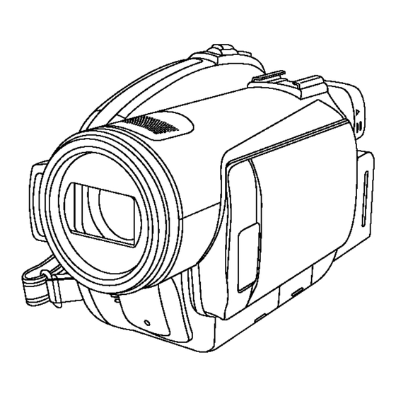
Page 13: Location Of Controls And Components
5 Location of Controls and Components Followings are the Location of Controls and Components for HDC-SX5P/PC as a sample. For other models, refer to each Operation Instructions. -
Page 15: Service Mode
6 Service Mode 6.1. Error Display is displayed automatically on the EVF or the LCD Monitor when an undesirable condition has occurred. -
Page 16: Service Menu
6.2. Service Menu When abnormal detection contents are confirmed, do the following operation. Automatic diagnosis code will dis- played.(Servise Menu) 1. Preparation Remove the SD card and disc from this machine. 2. Service menu is displayed. (see Fig. S1) Set mode dial to [DISC RECORDING MODE] of HD mode. Pushed [DELETE] button and [LEFT of CURSOR] button and [AUTO/MANUAL/FOCUS switch to FOCUS] button simulta- neously for 3 seconds. - Page 17 Display contents (Camera Error code contents) To exit the Service Menu Turn off the power. Make the error code clear after repair completion. CLEAR METHOD If the SD card and disc inserted, take out it before Service Menu operation. Set mode dial to [DISC RECORDING MODE] of HD mode. Pushed [DELETE] button, [RIGHT of CURSOR] button and [AUTO/MANUAL/FOCUS switch to FOCUS] button simultaneously for 3 seconds.
-
Page 18: Service Fixture & Tools
7 Service Fixture & Tools Parts Name Parts No. Q'ty Remarks Personal Computer AC Adaptor DC Cable AV Multi Cable USB Cable TATSUJIN PC-Adjustment Program Step Up Ring VFK1164TAR37 Light Box VFK1164LBX1 Infinity Lens VFK1164TCM02 With Focus Chart Extension Cable (150pin) VFK1582BF010 PP6001 (Main) - PS6201 (Sub) -
Page 19: Disassembly And Assembly Instructions
8 Disassembly and Assembly Instructions 8.1. Disassembly Flow Chart This flow chart indicates the disassembly steps the cabinet parts, P.C.B. and Mecha. Unit in order to access to be serviced. When reinstalling, perform the steps in the reverse order. -
Page 20: Layout
8.2. P.C.B. Layout Fig. F1... -
Page 21: Disassembly Procedures
8.3. Disassembly Procedures Item / Prat Fig. Removal (Screw,Connector,Flex. & Other) Flow-Chart for Disassembly Procedure Fig.D21 Open the LCD Unit. P.C.B. 1-Screw (Y) LCD Det P.C.B. Item / Prat Fig. Removal Caution): LCD Unit surely during (Screw,Connector,Flex. & Other) assemble the LCD Det P.C.B.. Front Case Fig.D2... - Page 22 Fig. D3 Fig. D1 Fig. D4 Fig. D2...
- Page 23 Fig. D5 Fig. D6...
- Page 24 Fig. D7 Fig. D9 Fig. D8...
- Page 25 Fig. D10 Fig. D12 Fig. D11 Fig. D13...
- Page 26 Fig. D14 Fig. D16 Fig. D15 Fig. D17...
- Page 27 Fig. D20 Fig. D18 Fig. D19 Fig. D21...
- Page 28 Fig. D22 Fig. D24 Fig. D23 Fig. D25...
- Page 29 Fig. D26 Fig. D28 Fig. D27 Fig. D29...
- Page 30 Fig. D30 Fig. D32 Fig. D31 Fig. D33...
-
Page 31: Disassembly Procedures Of Camera Lens Unit
8.4. Disassembly Procedures of Camera Lens Unit The following flowchart describes order or steps for removing the Camera lens unit and certain printed circuit boards in order to make access to the item needing service. To reassemble the unit follow the steps in reverse order. Fig.L1 Fig. -
Page 32: Measurements And Adjustments
9 Measurements and Adjustments 9.1. Service Positions 9.1.1. List of the extension cables Use the following extension cables when checking or adjusting individual circuit boards except module Parts (Main P.C.B. and Sub P.C.B.). - Page 33 9.1.2. Checking and repairing individual circuit boards except module part (Main P.C.B. and Sub P.C.B.) How to use extension cables.
-
Page 34: Location For Connectors Of The Module P.c.b. (Main P.c.b. And Sub P.c.b.)
9.2. Location for Connectors of the Module P.C.B. (Main P.C.B. and Sub P.C.B.) 9.2.1. Main P.C.B. - Page 35 9.2.2. Sub P.C.B.
-
Page 36: Electrical Adjustment Procedures
9.3. Electrical Adjustment Procedures 9.3.1. Computer assisted adjustment system <TATSUJIN> adjustment This unit employs the computer assisted system named; for Electrical adjustment. It is required to install a USB driver for service which can be download only from TSN-WEB. 9.3.2. Set-up manual for High Definition Video Camera Pay attention, because the adjustment method is different from this machine. - Page 37 Fig. E2 Rough image of set-up connection Part Number of jig • Only a necessary jig mentions it in setup of electric adjustment. Parts Name Parts No. Q'ty Remarks Personal Computer With Tatsujin Software. AC Adaptor The AC Adaptor for High Definition Video Camera DC Cable The AC Adaptor for High Definition Video Camera USB Cable...
- Page 38 9.3.3. Set up PC-EVR adjustment program 1. Turn on the PC and install the TATSUJIN Adjustment Pro- 6. Saving for EEPROM data is complete, menu will appear. gram into the PC. To perform each adjustment, display the adjustment 2. TATSUJIN PC-Adjustment Program start in the following menu by selecting the desired menu from procedure.
-
Page 39: Initial Guideline
9.3.4. Initial guideline The table below shows which adjustments are necessary according to the unit parts and individual parts to be replaced. Make sure to perform these adjustments shown below as necessary. -
Page 40: Maintenance
10 Maintenace 10.1. Cleaning Lens, Viewfinder and LCD Panel Do not touch the surface of the lens, Viewfinder and LCD Panel with your hand. When cleaning the lens, use air-Blower to blow off the dust. When cleaning the LCD Panel, dampen the lens cleaning paper with lens cleaner, and the gently wipe the their surface. Note: A lens cleaning paper and lens cleaner are available at local camera shops and market place. - Page 42 3.The voltage being indicated on the schematic diagram is measured in "Standard-Playback" mode when there is no specify mode is mentioned. Model No. HDC-SX5P HDC-SX5GC 4.Although the voltage and waveform available on here is measured with standard frame, it may be differ from actual measurement due to modification of circuit and so on.
-
Page 43: S2. Voltage And Waveform Chart
S2. Voltage and Waveform Chart Note) Indicated voltage values are the standard values for the unit measured by the DC electronic circuit tester (high-impedance) with the chassis taken as standard. Therefore, there may exist some errors in the voltage values, depending on the internal impedance of the DC circuit tester. S2.1. -
Page 44: S2.3. Evf B/L P.c.b
S2.3. EVF B/L P.C.B. S2.4. Monitor P.C.B. S2.5. Mic P.C.B. S2.6. Front P.C.B. S2.7. Flash P.C.B. <IC602> REF No. PIN No. REC REF No. PIN No. REC REF No. PIN No. REC REF No. PIN No. REC REF No. PIN No. REC Q801 Q901 IC4801... -
Page 45: S3. Block Diagram
S3. Block Diagram S3.1. Overall Block Diagram LENS UNIT 0.44"LCD EVF P.C.B. IC601 (CONTROLLER & IC4801 SIGNAL PROCESSOR) (MIC AMP) 2.7"WIDE LCD MONITOR P.C.B. SHUTTER ZOOM IRIS FOCUS SIDE (R) P.C.B. P.C.B. IC107 (V DRIVER) EXT MIC/ IC101 FREE STYLE (CG/SSG) REMOTE IC104,105,106... -
Page 46: S4. Schematic Diagram
S4. Schematic Diagram S4.1. Interconnection Diagram S4.1.1. Interconnection Diagram (1) LENS UNIT JACK P.C.B. SIDE CASE (L) UNIT ZOOM SD CARD MENU JK4001 JK4002 JK4003 LITHIUM BATTERY HS6301 PHOTO SHOT REC START/STOP EJECT MODE DIAL/ JOYSTICK D ELETE POWER (EVR) MAIN P.C.B. -
Page 47: S4.1.2. Interconnection Diagram (2
S4.1.2. Interconnection Diagram (2) S6701 CL6301 P6301 OPEN SPOUT1 CL6302 SPEAKER SPOUT2 FP6006 FP6301 LCD DET P.C.B. SPOUT1 PW EBL5V SPOUT1 PW EBL5V SPOUT1 EVF SLIDE SW SPOUT2 DOOR OPEN SPOUT2 CARD LED PW MBL5V PW REG3V PW MBL5V KEYIN5 LCD RVS SYSRST LCD OPEN... -
Page 48: S4.2. Jack Schematic Diagram
S4.2. Jack Schematic Diagram HDC-SX5 Series Jack Section (Jack P.C.B. (1/2)) Schematic Diagram... -
Page 49: S4.3. Sd Holder Schematic Diagram
S4.3. SD Holder Schematic Diagram HDC-SX5 Series SD Holder Section (Jack P.C.B. (2/2)) Schematic Diagram... -
Page 50: S4.4. Side R Schematic Diagram
S4.4. Side R Schematic Diagram HDC-SX5 Series Side R Section (Side R P.C.B. (1/2)) Schematic Diagram... -
Page 51: S4.5. Lcd Schematic Diagram
S4.5. LCD Schematic Diagram HDC-SX5 Series LCD Section (Side R P.C.B. (2/2)) Schematic Diagram S-10... -
Page 52: S4.6. Evf B/L Schematic Diagram
S4.6. EVF B/L Schematic Diagram HDC-SX5 Series EVF B/L Schematic Diagram S-11... -
Page 53: S4.7. Monitor Schematic Diagram
S4.7. Monitor Schematic Diagram HDC-SX5 Series Monitor Schematic Diagram S-12... -
Page 54: S4.8. Mic Schematic Diagram
S4.8. Mic Schematic Diagram HDC-SX5 Series Schematic Diagram S-13... -
Page 55: S4.9. Front Cn Schematic Diagram
S4.9. Front CN Schematic Diagram HDC-SX5 Series Front CN Section (Front P.C.B. (1/2)) Schematic Diagram S-14... -
Page 56: S4.10. Lens Ba Schematic Diagram
S4.10. Lens BA Schematic Diagram HDC-SX5 Series Lens BA Section (Front P.C.B. (2/2)) Schematic Diagram S-15... -
Page 57: S4.11. Flash Schematic Diagram
S4.11. Flash Schematic Diagram HDC-SX5 Series Flash Schematic Diagram S-16... -
Page 58: S4.12. Drive Extend Schematic Diagram
S4.12. Drive Extend Schematic Diagram HDC-SX5 Series Drive Extend Schematic Diagram S-17... -
Page 59: S4.13. Lcd Det Schematic Diagram
S4.13. LCD DET Schematic Diagram / S4.14. Battery Schematic Diagram HDC-SX5 Series HDC-SX5 Series LCD DET Battery Schematic Diagram Schematic Diagram S-18... - Page 60 S-19...
-
Page 61: S4.15. Ccd Fpc Schematic Diagram
S4.15. CCD FPC Schematic Diagram HDC-SX5 Series CCD FPC Schematic Diagram S-20 S-20... - Page 62 HDC-SX5 Series CCD FPC Schematic Diagram S-21 S-21...
- Page 63 HDC-SX5 Series CCD FPC Schematic Diagram S-22...
- Page 64 HDC-SX5 Series CCD FPC Schematic Diagram S-23...
-
Page 65: S5. Print Circuit Board
S5. Print Circuit Board S5.1. Jack P.C.B. S5.1.1. Jack P.C.B. (Component Side) (Component Side) HDC-SX5 Series Jack P.C.B. (Component Side) S-24... -
Page 66: S5.1.2. Jack P.c.b. (Foil Side
S5.1.2. Jack P.C.B. (Foil Side) (Foil Side) HDC-SX5 Series Jack P.C.B. (Foil Side) S-25... -
Page 67: S5.2. Side R P.c.b
S5.2. Side R P.C.B. S5.2.1. Side R P.C.B. (Component Side) (Component Side) HDC-SX5 Series Side R P.C.B. (Component Side) S-26... -
Page 68: S5.2.2. Side R P.c.b. (Foil Side
S5.2.2. Side R P.C.B. (Foil Side) (Foil Side) HDC-SX5 Series Side R P.C.B. (Foil Side) S-27... -
Page 69: S5.3. Evf B/L P.c.b
S5.3. EVF B/L P.C.B. (Component Side) (Foil Side) HDC-SX5 Series EVF B/L P.C.B. S-28... -
Page 70: S5.4. Monitor P.c.b
S5.4. Monitor P.C.B. S5.4.1. Monitor P.C.B. (Component Side) (Component Side) HDC-SX5 Series Monitor P.C.B. (Component Side) S-29... -
Page 71: S5.4.2. Monitor P.c.b. (Foil Side
S5.4.2. Monitor P.C.B. (Foil Side) (Foil Side) HDC-SX5 Series Monitor P.C.B. (Foil Side) S-30... -
Page 72: S5.5. Mic P.c.b
S5.5. Mic P.C.B. (Component Side) (Foil Side) HDC-SX5 Series Mic P.C.B. S-31... -
Page 73: S5.6. Front P.c.b
S5.6. Front P.C.B. (Component Side) (Foil Side) HDC-SX5 Series Front P.C.B. S-32... -
Page 74: S5.7. Flash P.c.b
S5.7. Flash P.C.B. (Component Side) (Foil Side) HDC-SX5 Series Flash P.C.B. S-33... -
Page 75: S5.8. Drive Extend P.c.b
S5.8. Drive Extend P.C.B. (Component Side) (Foil Side) HDC-SX5 Series Drive Extend P.C.B. S-34... -
Page 76: S5.9. Lcd Det P.c.b
S5.9. LCD DET P.C.B. / S5.10. Battery P.C.B. (Foil Side) (Component Side) (Foil Side) HDC-SX5 Series HDC-SX5 Series LCD DET P.C.B. Battery P.C.B. S-35... -
Page 77: S5.11. Ccd Fpc P.c.b
S5.11. CCD FPC P.C.B. S5.11.1. CCD FPC P.C.B. (Component Side) (Component Side) HDC-SX5 Series CCD FPC P.C.B. (Component Side) S-36... -
Page 78: S5.11.2. Ccd Fpc P.c.b. (Foil Side
S5.11.2. CCD FPC P.C.B. (Foil Side) (Foil Side) HDC-SX5 Series CCD FPC P.C.B. (Foil Side) S-37... - Page 79 S-38...
-
Page 80: S6. Replacement Parts List
S6. Replacement Parts List Note: 1.* Be sure to make your orders of replacement parts according to this list. 2. IMPORTANT SAFETY NOTICE Components identified with the mark have the special characteristics for safety. When replacing any of these components, use only the same type. 3. - Page 81 HDC-SX5EG-S,E-S,EP-S,EB-S,GC-S,GCS-S,SG-S,EE-S,GN-S,GK-S,P-S,PC-S,PL-S vol.1 Ref.No. Part No. Part Name & Description Remarks Ref.No. Part No. Part Name & Description Remarks LB4012 J0JYC0000061 FILTER VEP03H39B MAIN P.C.B. 1 (RTL) EG/E/EP/EB LB4013 J0JYC0000061 FILTER LB4014 J0JYC0000059 FILTER VEP03H39C MAIN P.C.B. 1 (RTL) GC/SG LB4016 J0JYC0000061 FILTER LB40015...
- Page 82 HDC-SX5EG-S,E-S,EP-S,EB-S,GC-S,GCS-S,SG-S,EE-S,GN-S,GK-S,P-S,PC-S,PL-S vol.1 Ref.No. Part No. Part Name & Description Remarks Ref.No. Part No. Part Name & Description Remarks R804 ERJ2RKD560 M.RESISTOR CH 1/16W 56 LB6301 J0JYC0000061 FILTER LB6302 J0JYC0000061 FILTER LB6303 J0JYC0000061 FILTER LB6304 J0JYC0000061 FILTER VEP26301A MONITOR P.C.B. (RTL) LB6305 J0JYC0000061 FILTER...
- Page 83 HDC-SX5EG-S,E-S,EP-S,EB-S,GC-S,GCS-S,SG-S,EE-S,GN-S,GK-S,P-S,PC-S,PL-S vol.1 Ref.No. Part No. Part Name & Description Remarks Ref.No. Part No. Part Name & Description Remarks QR7008 UNR92A4J0L TRANSISTOR C481 F3F0J226A032 T.CAPACITOR CH 6.3V 22U C483 F3F0J476A032 E.CAPACITOR CH 6.3V 47U R7001 ERJ2GEJ473Y M.RESISTOR CH 1/16W 47K C484 F3F0J226A032 T.CAPACITOR CH 6.3V 22U R7003...
- Page 84 HDC-SX5EG-S,E-S,EP-S,EB-S,GC-S,GCS-S,SG-S,EE-S,GN-S,GK-S,P-S,PC-S,PL-S vol.1 Ref.No. Part No. Part Name & Description Remarks Ref.No. Part No. Part Name & Description Remarks XQN16+BJ5FN SCREW 1 VXY1980C DVD DRIVE UNIT 1 EG,E,EP,EB,GC XQN16+BJ5FN SCREW 1 VXY1980D DVD DRIVE UNIT 1 GCS,SG XQN16+BJ5FN SCREW ...
- Page 85 HDC-SX5EG-S,E-S,EP-S,EB-S,GC-S,GCS-S,SG-S,EE-S,GN-S,GK-S,P-S,PC-S,PL-S vol.1 Ref.No. Part No. Part Name & Description Remarks Ref.No. Part No. Part Name & Description Remarks XQN16+BJ8FN SCREW VYK2H35 SIDE CASE R (3) U 1 (EXCEPT P,PC,GK) XQN16+BJ4FN SCREW VYK2H36 SIDE CASE R (3) U 1 GK XQN16+BJ6FN SCREW VYK2H32 SIDE CASE R (3) U XQN16+BJ6FN SCREW...
- Page 86 HDC-SX5EG-S,E-S,EP-S,EB-S,GC-S,GCS-S,SG-S,EE-S,GN-S,GK-S,P-S,PC-S,PL-S vol.1 Ref.No. Part No. Part Name & Description Remarks Ref.No. Part No. Part Name & Description Remarks VKM7239 LCD CASE (B) L5BDDXP00001 LCD PANEL VGQ9584 LIGHTING PLATE HOLDER VGL1253 PRISM SHEET A VGL1254 PRISM SHEET B VGL1255 DIFFUSION SHEET VKW3365 LIGHTING PLATE VGL1256...
- Page 87 HDC-SX5EG-S,E-S,EP-S,EB-S,GC-S,GCS-S,SG-S,EE-S,GN-S,GK-S,P-S,PC-S,PL-S vol.1 Ref.No. Part No. Part Name & Description Remarks Ref.No. Part No. Part Name & Description Remarks VSC5761 CCD HEAT SINK PLATE VGQ9692 BARRIER (A) VXQ1520 PRISM U 301-1 VEP22383A CCD FPC 1 (RTL) 301-2 VGQ9217 CCD HEAT TRANSFER SHEET VXW0887 LENS U 302-1...
- Page 88 HDC-SX5EG-S,E-S,EP-S,EB-S,GC-S,GCS-S,SG-S,EE-S,GN-S,GK-S,P-S,PC-S,PL-S vol.1 Ref.No. Part No. Part Name & Description Remarks Ref.No. Part No. Part Name & Description Remarks VEP29195A EVF FPC VGQ9196 SLIDE SPACER VGQ9196 SLIDE SPACER VGQ9117 LENS HOLDER VDL1906 EVF LENS VGQ9576 EVF CASE VGU0B97 SIGHT LEVER L5BDDXK00013 LCD PANEL VGL1217 EVF DIFFUSION SHEET VGQ9121...
- Page 89 HDC-SX5EG-S,E-S,EP-S,EB-S,GC-S,GCS-S,SG-S,EE-S,GN-S,GK-S,P-S,PC-S,PL-S vol.1 Ref.No. Part No. Part Name & Description Remarks Ref.No. Part No. Part Name & Description Remarks K2GJYYC00001 DC CABLE K2KC4CB00024 AV CABLE K2KZ9DB00004 D TERMINAL CABLE 505 K2CQ2CA00006 AC CORD 1 EG,E,EP,GC,GCS,SG,EE 505 K2CT3CA00004 AC CORD 1 EB,GC,GCS,SG ...
-
Page 90: S7. Exploded View
S7. Exploded View S7.1. Frame and Casing Section (1) 21 (RTL) BATTERY P.C.B. 3 (RTL) SUB P.C.B. 2 (RTL) MAIN P.C.B. 5 (RTL) DRIVE EXTENDED P.C.B. 16 (RTL) JACK P.C.B. 4 (RTL) FLASH P.C.B. S-49... -
Page 91: S7.2. Frame And Casing Section (2
S7.2. Frame and Casing Section (2) 67 (RTL) MIC P.C.B. 71 (RTL) FRONT P.C.B. 31 (RTL) SIDE R P.C.B. 32 (RTL) LCD DET P.C.B. S-50... -
Page 92: S7.3. Lcd Section
S7.3. LCD Section 210 (RTL) MONITOR P.C.B. B201 B202 S-51... -
Page 93: S7.4. Camera Lens Section
S7.4. Camera Lens Section B308 301-2 301-1 B315 B314 B313 B312 302-10 302-3 302-9 B311 302-6 B307 B306 B302 302-4 B301 B303 302-1 302-7 302-2 302-8 302-5 B305 B304 S-52... -
Page 94: S7.5. Evf Section
S7.5. EVF Section B405 B401 B402 B407 B408 B403 B406 B404 412 (RTL) EVF B/L P.C.B. S-53... -
Page 95: S7.6. Packing Parts And Accessories Section
S7.6. Packing Parts and Accessories Section (EB/GC/GCS/SG) (E/EG/EP/GC/GCS/SG/EE) (P/PC/PL) (GK) (GN) Battery Pack Unit S-54...
Need help?
Do you have a question about the HDC-SX5P and is the answer not in the manual?
Questions and answers