Table of Contents
Advertisement
Advertisement
Table of Contents

Related Manuals for AC Tech SCF series


Summary of Contents for AC Tech SCF series
- Page 1 SCF Series Installation and Operation Manual...
-
Page 2: Table Of Contents
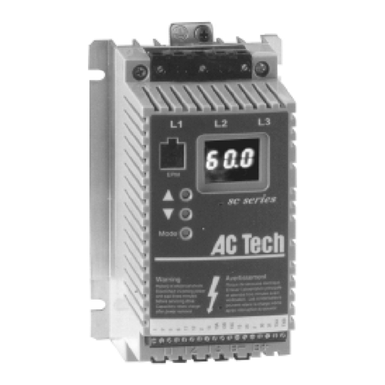
Manual Number: IMSF09-e1 TABLE OF CONTENTS GENERAL..................1 SCF DIMENSIONS............... 2 THROUGH-HOLE MOUNT DIMENSIONS......... 4 SCF MODEL DESIGNATION CODE........6 SCF SPECIFICATIONS............... 7 SCF RATINGS................7 INSTALLATION................10 INPUT AC POWER REQUIREMENTS........11 POWER WIRING................. 13 SCF POWER WIRING DIAGRAM..........14 10.0 CONTROL WIRING.............. - Page 3 THE SCF SUB-MICRO DRIVE INPUT POWER TERMINALS GROUND ELECTRONIC 3-DIGIT LED PROGRAMMING DISPLAY MODULE (EPM) PROGRAMMING BUTTONS CONTROL TERMINAL STRIP OUTPUT (MOTOR) TERMINALS...
-
Page 4: General
WARRANTY AC Technology Corporation warrants the SCF Series AC motor control to be free of defects in material and workmanship for a period of twelve months from the date of sale to the user, or eighteen months from the date of shipment, which ever occurs first. -
Page 5: Scf Dimensions
SCF DIMENSIONS 0.38" If R < 6.30" S = 0.19" T = 0.38" U = 0.18" V = 0.69" If R = 6.30" S = 0.28" T = 0.50" Dia. Slot U = 0.24" V = 0.92" Mounting Tab Detail INPUT VOLTAGE MODEL... - Page 6 INPUT VOLTAGE MODEL 208 / 240 SF220Y 5.75 3.76 6.74 3.40 4.37 208 / 240 SF220 5.75 2.88 5.56 2.60 3.06 400 / 480 SF420 5.75 2.88 5.56 2.60 4.37 480 / 590 SF520 5.75 2.88 5.56 2.60 4.37 208 / 240 SF230Y 5.75 3.76...
-
Page 7: Through-Hole Mount Dimensions
SCF THROUGH-HOLE MOUNT DIMENSIONS INPUT VOLTAGE MODEL 0.75 120 / 208 / 240 SF110SF 7.72 6.80 4.75 1.20 208 / 240 SF210YF 7.72 6.80 4.37 1.20 208 / 240 SF210F 7.72 6.80 4.37 1.20 400 / 480 SF410F 7.72 6.80 4.37 1.20 480 / 590... - Page 8 INPUT VOLTAGE MODEL 208 / 240 SF275F 11.59 11.14 7.65 3.60 400 / 480 SF475F 9.59 11.14 7.65 3.60 480 / 590 SF575F 9.59 11.14 7.65 3.60 208 / 240 SF2100F 15.59 11.14 7.65 3.60 400 / 480 SF4100F 11.59 11.14 7.65 3.60...
-
Page 9: Scf Model Designation Code
SCF MODEL DESIGNATION CODE The SCF model number gives a full description of the basic drive unit (see example below). EXAMPLE: SF210Y (SCF Series, 208/240 Vac, 1 HP, single or three phase input) Series: = SCF Series Variable Speed AC Motor Drive Input Voltage: = 120/208/240 Vac (For 110 to 120 Vac and 208 to 240 Vac;... -
Page 10: Scf Specifications
SCF SPECIFICATIONS Storage Temperature -20 to 70 C Ambient Operating Temperature 0 to 50 C (up to 6 kHz carrier, derate above 6 kHz) Ambient Humidity < 95% (non-condensing) Maximum Altitude 3300 ft (1000 m) above sea level (without derating) Input Line Voltages 120/208/240 Vac, 208/240 Vac, 400/480 Vac, 480/590 Vac Input Voltage Tolerance... - Page 11 FOR MOTORS INPUT (50-60 Hz) HEAT LOSS MODEL OUTPUT RATED (WATTS) NUMBER INPUT CURRENT POWER CURRENT (NOTE 6) (NOTE 1) PHASE (AMPS) (kVA) (AMPS) SF200Y SERIES (NOTE 3) 208 / 240 Vac 0 - 200 / 230 Vac THRU SF203Y 0.25 0.20 3.6 / 3.2...
- Page 12 FOR MOTORS INPUT (50-60 Hz) HEAT LOSS MODEL OUTPUT RATED (WATTS) NUMBER INPUT CURRENT POWER CURRENT (NOTE 6) (NOTE 1) PHASE (AMPS) (kVA) (AMPS) SF400 SERIES (NOTE 4) 400 / 480 Vac 0 - 400 / 460 Vac THRU SF405 0.37 1.6 / 1.4 1.3 / 1.1...
-
Page 13: Installation
(from the drive(s) and other heat sources), the maximum allowable temperature inside the enclosure, the maximum ambient temperature outside the enclosure, and the enclosure properties. The SCF Series is UL approved for solid state motor overload protection. Therefore, a separate thermal overload relay is not required for single motor applications. -
Page 14: Input Ac Power Requirements
In order to reform the capacitors and prepare the drive for operation after a long period of inactivity, apply input power to the drive for 8 hours prior to actually operating the motor. EXPLOSION PROOF APPLICATIONS Explosion proof motors that are not rated for inverter use lose their certification when used for variable speed. - Page 15 INPUT VOLTAGE RATINGS SF100 Series drives are rated for 120/208/240 Vac, single phase, 50-60 Hz input. The drive will function with input voltage of 120 Vac (+10%, -15%), at 48 to 60 Hz, or with input voltage of 208 to 240 Vac (+ 10%, - 15%), at 48 to 62 Hz.
-
Page 16: Power Wiring
POWER WIRING WARNING! Hazard of electrical shock! Capacitors retain charge after power is removed. Disconnect incoming power and wait until the voltage between terminals B+ and B- is 0 VDC before servicing the drive. Note drive input and output current ratings and check applicable electrical codes for required wire type and size, grounding requirements, over-current protection, and incoming power disconnect, before wiring the drive. -
Page 17: Scf Power Wiring Diagram
SCF POWER WIRING DIAGRAM THREE PHASE INPUT 120 Vac SINGLE PHASE INPUT (SF200, SF200Y, SF400, (SF100 SERIES) AND SF500 SERIES) 208/240 Vac SINGLE PHASE INPUT OUTPUT (ALL SERIES) (SF100 AND SF200Y SERIES) T1 T2 T3 B- B+ On SF200Y models, this terminal is labeled L3. -
Page 18: Control Wiring
10.0 CONTROL WIRING 10.1 CONTROL WIRING VS. POWER WIRING External control wiring MUST be run in a separate conduit away from all other input and output power wiring. If control wiring is not kept separate from power wiring, electrical noise may be generated on the control wiring that will cause erratic drive behavior. - Page 19 10.6 SPEED REFERENCE SELECTION If an analog speed reference input is used to control the drive speed, terminal TB-13A, 13B, or 13C (Parameter 10, 11, or 12) may be programmed as the input select for the desired analog input signal. When that TB-13 terminal is then closed to TB-2, the drive will follow the selected analog speed reference input.
- Page 20 NOTE: If TB-13A, TB-13B, and TB-13C are all programmed to select speed references, and two or three of the terminals are closed to TB-2, the higher terminal has priority and will override the others. For example, if TB-13A is programmed to select 0-10VDC, and TB-13C is programmed to select PRESET SPEED #3, closing both terminals to TB-2 will cause the drive to respond to PRESET SPEED #3, because TB-13C overrides TB-13A.
-
Page 21: Scf Control Wiring Diagrams
11.0 SCF CONTROL WIRING DIAGRAMS 11.1 SCF TERMINAL STRIP Shown below is the terminal strip on the main control board, along with a brief description of the function of each terminal. The TB-2 terminals are internally connected to each other 1 2 5 6 13A 13B 13C TXA TXB... - Page 22 11.2 TWO-WIRE START/STOP CONTROL Shown below is the wiring diagram for a typical two-wire start/stop control scheme, using one maintained contact (such as that from a PLC) for RUN and STOP commands. The TB-2 terminals are internally connected to each other 2 5 6 13A 13B 13C TXA TXB...
- Page 23 11.3 ALTERNATE TWO-WIRE START/STOP CONTROL Shown below is the wiring diagram for an alternate two-wire start/stop control scheme, using one maintained contact for RUN FORWARD and another maintained contact for RUN REVERSE. The TB-2 terminals are internally connected to each other 2 5 6 13A 13B 13C TXA TXB...
- Page 24 11.4 THREE-WIRE START/STOP CONTROL Shown below is the wiring diagram for a typical three-wire start/stop control scheme, using momentary contacts (such as pushbuttons) for START and STOP commands. The TB-2 terminals are internally connected to each other 1 2 5 6 13A 13B 13C TXA TXB MOMENTARY...
- Page 25 11.5 SPEED POT AND PRESET SPEED CONTROL Shown below is the wiring for SPEED POT and/or PRESET SPEED control, and either a two-wire or three-wire start/stop circuit: The TB-2 terminals are internally connected to each other 1 2 5 6 13A 13B 13C TXA TXB 2.5k-10kΩ...
-
Page 26: Initial Power Up And Motor Rotation
12.0 INITIAL POWER UP AND MOTOR ROTATION WARNING! DO NOT connect incoming AC power to output terminals T1, T2, and T3! Severe damage to the drive will result. Do not continuously cycle input power to the drive more than once every two minutes. - Page 27 Follow the procedure below to check the motor rotation. This procedure assumes that the drive has been powered up for the first time, and that none of the parameters have been changed. 1. Use the ! button to decrease the speed setpoint to 00.0 Hz. The left decimal point will illuminate as the speed setpoint is decreased.
-
Page 28: Programming The Scf Drive
13.0 PROGRAMMING THE SCF DRIVE The drive may be programmed by one of three methods: using the three buttons and 3-digit LED display on the front of the drive, programming the Electronic Programming Module (EPM) using the optional EPM Programmer, and through a serial link using serial communications. This section describes programming the drive using the buttons and display, which are shown below: BUTTONS DISPLAY... - Page 29 NOTE: If the display flashes “Er”, the password was incorrect, and the process to enter the password must be repeated. Use the " and ! buttons to scroll to the desired parameter number. In the example below, Parameter 19 is being displayed, which is the ACCELERATION TIME of the drive: Use "...
- Page 30 13.1 SETTING VALUES IN TENTHS OF UNITS ABOVE 100 Parameter settings and the keypad speed command can always be adjusted in tenths of unit increments from 0.0 to 99.9. Above 100 however, values can be set in whole units or tenths of units, depending on the setting of Parameter 16 - UNITS EDITING.
- Page 31 EPM is installed. The SCF Series drive contains two or three sets of parameter values, depending on whether the drive has been programmed with optional OEM default settings. The first set of values is the factory default settings, which are permanently stored on the main control board and cannot be changed.
-
Page 32: Parameter Menu
14.0 PARAMETER MENU FACTORY PARAMETER NAME RANGE OF ADJUSTMENT DEFAULT (NOTE 1) LINE VOLTAGE HIGH (01), LOW (02) HIGH (01) CARRIER FREQUENCY 4kHz (01), 6 kHz (02), 8 kHz (03), 10 kHz (04) 6 kHz (02) START METHOD NORMAL (01), START ON POWER UP (02), NORMAL (01) START WITH DC BRAKE (03), AUTO RESTART WITH DC BRAKE (04),... - Page 33 PARAMETER MENU (CONT’D) FACTORY PARAMETER NAME RANGE OF ADUSTMENT DEFAULT (NOTE 1) TB-13C FUNCTION NONE (01), 0-10 VDC (02), 4-20 mA (03), NONE (01) SELECT PRESET SPEED #3 (04), INCREASE FREQ (05), EXTERNAL FAULT (06), REMOTE KEYPAD (07), DB FAULT (08), ACCEL/DECEL #2 (09) TB-15 OUTPUT (SEE PARAMETER 6 - TB-14 OUTPUT) NONE (01)
- Page 34 PARAMETER MENU (CONT’D) FACTORY PARAMETER NAME RANGE OF ADJUSTMENT DEFAULT (NOTE 1) BASE FREQUENCY 25.0 - 500.0 Hz (NOTE 4) 60.0 Hz FIXED BOOST 0.0 - 30.0 % 1.0 % ACCEL BOOST 0.0 - 20.0 % 0.0 % SLIP COMPENSATION 0.0 - 5.0 % 0.0 % 31-37...
-
Page 35: Description Of Parameters
15.0 DESCRIPTION OF PARAMETERS LINE VOLTAGE SELECTION This calibrates the drive for the actual applied input voltage, and can be set to HIGH (01) or LOW (02). Refer to the table below for the proper setting depending on the input voltage. RATED INPUT INPUT APPLIED INPUT... - Page 36 NOTE 3: If this parameter is changed while the drive is running, the change will not take effect until the drive is stopped. Therefore, the allowable maximum frequency for drives with the High Output Frequency option (see NOTE 1) will not change if the carrier frequency is changed while the drive is running.
- Page 37 STOP METHOD COAST TO STOP: When a STOP command is given, the drive shuts off the output to the motor, allowing it to coast freely to a stop. COAST WITH DC BRAKE: When a stop command is given, the drive will activate DC braking (after a delay of up to 2 seconds, depending on frequency) to help decelerate the load.
- Page 38 AT SET SPEED: Closes if the drive is within + 0.5 Hz of the speed setpoint. ABOVE PRESET SPEED #3: Closes if the output frequency exceeds the PRESET SPEED #3 setting. Opens if the output frequency is equal to or less than PRESET SPEED #3 (Parameter 33).
- Page 39 TB-13A FUNCTION SELECT This selects the function of terminal TB-13A. Closing TB-13A to TB-2 (or opening in the case of settings 7 and 10) activates the selected function. The following functions can be selected: NONE: Disables the TB-13A function. 0-10 VDC: Selects a 0-10 VDC signal (at TB-5) as the AUTO speed reference input. 4-20 mA: Selects a 4-20 mA signal (at TB-25) as the AUTO speed reference input.
- Page 40 0-10 VDC: Selects a 0-10 VDC signal (at TB-5) as the AUTO speed reference input. 4-20 mA: Selects a 4-20 mA signal (at TB-25) as the AUTO speed reference input. PRESET SPEED #2: Selects PRESET SPEED #2 as the AUTO speed reference. The drive will operate at the frequency programmed into Parameter 32.
- Page 41 EXTERNAL FAULT: Sets TB-13C as a normally closed external fault input. If TB-13C is open with respect to TB-2, the drive will fault. REMOTE KEYPAD: Selects the optional remote keypad as the control source. Refer to Parameter 14 - CONTROL. DB FAULT: Sets TB-13C as a dynamic braking fault input when using the optional dynamic braking module.
- Page 42 DISABLED: Disables the serial link 9600, 8, N, 2 - ENABLED WITH TIMER 9600, 8, N, 2 - ENABLED WITHOUT TIMER 9600, 8, E, 1 - ENABLED WITH TIMER 9600, 8, E, 1 - ENABLED WITHOUT TIMER 9600, 8, O, 1 - ENABLED WITH TIMER 9600, 8, O, 1 - ENABLED WITHOUT TIMER UNITS EDITING This allows parameter and keypad speed editing in whole units or tenths of units above 100.
- Page 43 DC BRAKE VOLTAGE This sets the magnitude of the DC braking voltage, in percentage of the nominal DC Bus voltage (DC Bus = input AC voltage X 1.414). The point at which the DC braking is activated depends on the selected STOP METHOD (Parameter 04): If COAST WITH DC BRAKE is selected, the DC braking is activated after a time delay of up to 2 seconds, depending on the output frequency at the time of the STOP command.
- Page 44 V/Hz ratio (see diagram below). For better out-of-the-box performance, SCF Series drives are shipped with a setting that is different from the factory default, as seen in the table below. If a factory reset is performed, FIXED BOOST will default to 1.0 %.
- Page 45 ACCELERATION BOOST ACCELERATION BOOST helps accelerate high-inertia loads. During acceleration, the output voltage is increased to increase motor torque. Once the motor reaches the new speed setpoint, the boost is turned off and the output voltage returns to the normal value. SLIP COMPENSATION SLIP COMPENSATION is used to counteract changes in motor speed (slip) caused by changes in load.
- Page 46 Example: The critical frequency is 23 Hz, and it is desired to skip a frequency range of 3 Hz above and below the critical frequency (therefore the skip range is 20 to 26 Hz). PRESET SPEED #6 or #7 would be set to 20 Hz, and the SKIP BANDWIDTH would be set to 6.0 Hz. If the drive is running at a speed below the skip range, and it is given a speed command that is within the skip range, the drive will accelerate to the start of the skip range (20 Hz in the example) and run at that speed until the speed command is greater than or equal to the "top"...
- Page 47 ACCEL / DECEL #2 This parameter sets the second acceleration and deceleration rate of the drive. To activate this acceleration and deceleration rate, use terminal TB-13A, TB-13B or T-13C. TB-13A and TB-13B can be set to AUXILIARY STOP which will cause the drive to decelerate to a stop according to the time programmed in this parameter.
- Page 48 TRANSLATE: If an EPM from a drive with a previous parameter version is installed in a new drive, the new drive will function like the previous version drive, but none of the parameter settings can be changed ("cE" will be displayed if this is attempted). The TRANSLATE function converts the EPM to the new parameter version so that the parameters can be changed, but it also retains the old parameter settings so the new drive will operate like the old drive without having to re-program all of the parameters.
- Page 49 MOTOR LOAD This displays the motor load in percent of the drive’s output current rating. 0-10 VDC ANALOG INPUT This displays the level of the 0-10 VDC analog input signal at TB-5. A reading of 100% indicates a 10 VDC input at TB-5. 4-20 mA ANALOG INPUT This displays the level of the 4-20 mA analog input signal at TB-25.
-
Page 50: Troubleshooting
P59-P60 TB-30 and TB-31 ANALOG OUTPUT This displays the level of the analog output signals at TB-30 (Parameter 59) and TB-31 (Parameter 60). A reading of 100% indicates that the output is 10 VDC. 16.0 TROUBLESHOOTING To aid in troubleshooting, Parameters 50 through 60 can be accessed without entering the PASSWORD. Simply press the Mode button twice to “skip”... - Page 51 The table below lists the fault conditions that will cause the drive to shut down, as well as some possible causes. Please contact the factory for more information on troubleshooting faults. FAULT MESSAGES DESCRIPTION & POSSIBLE CAUSES FAULT High Temperature Fault: Ambient temperature is too high; Cooling fan has failed (if equipped). Control Fault: A blank EPM, or an EPM with corrupted data has been installed.
-
Page 52: Scf Display Messages
17.0 SCF DISPLAY MESSAGES The following describes the various displays and messages that can appear on the SCF drive. 17.1 SPEED DISPLAY If the drive is in a STOP state (indicated by "- - -" on the display), and the commanded speed is changed, the display will show the commanded speed, and the upper left decimal point will turn on solid. - Page 53 SPEED SOURCE DISPLAYS DISPLAY DESCRIPTION CONTROL PAD: Speed is set using the ! and " buttons on the front of the drive. EXTERNAL CURRENT: Speed is controlled by a 4-20 mA signal wired to TB-25 and TB-2 EXTERNAL VOLTAGE: Speed is controlled by a 0-10 VDC signal wired to TB-5 and TB-2. JOG: The drive is in Jog mode, and the speed is set by Preset Speed #2 (Parameter 32).
-
Page 54: Appendix A - Through-Hole Mount Option
APPENDIX A - THROUGH-HOLE MOUNT OPTION The Through-Hole Mount option for the SCF drive allows the drive to be mounted with the heatsink outside of the enclosure for better heat dissipation. This is done by using a special heatsink that mounts to the outside of the enclosure. - Page 55 THROUGH-HOLE MOUNT DIMENSIONS FOR MODELS UP TO 10 HP MODEL SF110SF 7.72 6.80 2.76 2.76 6.00 2.69 N / A N / A N / A SF210YF 7.72 6.80 2.76 2.76 6.00 2.69 N / A N / A N / A SF210F 7.72 6.80...
- Page 56 THROUGH-HOLE DRAWING FOR 15 HP AND 20 HP MODELS This drawing applies to the following models only: SF2150F, SF4150F, SF5150F, SF4200F, and SF5200F. 2.24 2.24 1.04 1.04 0.24 HEATSINK 0.63 MOUNTING HOLES (#8) PANEL CUTOUT 0.63 1.04 2.24 2.24 1.04 10.14 11.14 THROUGH-HOLE CUTOUT DIMENSIONS FOR 15 HP AND 20 HP MODELS...
- Page 57 THROUGH-HOLE MOUNT DRAWING FOR 25 HP MODELS This drawing applies to SF4250F and SF5250F models only. 3.00 2.50 2.50 1.34 0.50 1.00 3.00 HEATSINK 1.50 3.00 MOUNTING HOLES (#10) 3.00 0.75 0.75 3.00 28.50 3.00 3.00 3.00 PANEL CUTOUT 3.00 1.50 2.50 10.34...
-
Page 58: Appendix B - Pi Setpoint Control Option
APPENDIX B - PI SETPOINT CONTROL OPTION The following describes the PI Setpoint Control software option for the SCF drive. This software option has additional parameters compared to the standard SCF drive. Also, some of the parameters found in the standard drive have changed in the PI version. PI Setpoint Control allows the SCF drive to maintain a process setpoint, such as PSI or CFM, without using an external controller. - Page 59 SETPOINT REFERENCES The following references can be used to adjust the process setpoint: 1. Keypad (! and " buttons) 2. 0-10 VDC signal (from speed pot or other source) 3. 4-20 mA signal 4. Preset Setpoints (using Preset Speeds #4 and #5) NOTE: The setpoint reference and the PI feedback cannot be the same signal.
- Page 60 DESCRIPTION OF PI PARAMETERS TB-13A FUNCTION SELECT KEYPAD SETPOINT: This option has been added so that the ! and " buttons on the front of the drive can be used as the PI setpoint reference source. Closing TB-13A to TB-2 will enable the PI mode and the ! and "...
- Page 61 MAX FEEDBACK This parameter should be set to the value of the process variable that corresponds to the maximum transducer feedback signal (10 VDC or 20 mA). See the example below. Example: A 0-100 psi transducer outputs 4 mA at 0 psi and 20 mA at 100 psi. Set MIN FEEDBACK to 0, and set MAX FEEDBACK to 100.
- Page 62 0-10 VDC FEEDBACK This can be used to monitor the PI feedback when using a 0-10 VDC feedback signal. The displayed value will be scaled according to the MIN and MAX FEEDBACK parameters (62 and 63). 4-20 mA FEEDBACK This can be used to monitor the PI feedback when using a 4-20 mA feedback signal. The displayed value will be scaled according to the MIN and MAX FEEDBACK parameters (62 and 63).
- Page 63 SCF SERIES PI CONTROL WIRING EXAMPLES The following diagrams illustrate the most common PI control configurations. The wiring and corresponding parameter settings are given. In these examples, TB-13A is used to select the setpoint reference (TB-13B or TB-13C could also be used for this function). The examples show a 2-wire start/stop circuit.
- Page 64 Example 2: Speed Pot Setpoint and 4-20 mA Feedback 11 12 14 13A 13C 15 Speed Pot Start/Stop Speed Pot Setpoint Select 4-20 mA Contact Feedback (PI Mode Enable/Disable) - Set PI MODE (Parameter 61) to NORMAL 4-20 mA (02) or REVERSE 4-20 mA (04) depending on the system.
- Page 65 TUNING THE PI CONTROL Once the PI control is configured properly, it needs to be tuned in order to maintain the process setpoint. First, set the Integral Gain (Parameter 65) to zero, and increase the Proportional Gain (Parameter 64) until the system becomes unstable, then lower the gain until the system stabilizes again.
- Page 66 Declaration relates, are in conformity with the relevant provisions of the following standards, provided that installations are carried out in accordance with manufacturer’s instructions. PRODUCTS RELATED TO DECLARATION SCF Series AC Variable Frequency Motor Drives Models: SF103S SF210Y SF215 SF2150...
- Page 67 A C Technology Corporation 660 Douglas Street, Uxbridge MA 01569 Sales: 800-217-9100, FAX: 508-278-7873 Service: 508-278-9100 ext 125, FAX: 508-278-6620 www.actechdrives.com...
Need help?
Do you have a question about the SCF series and is the answer not in the manual?
Questions and answers