Table of Contents
Advertisement
Quick Links
Download this manual
See also:
Instruction Manual
CD RECEIVER
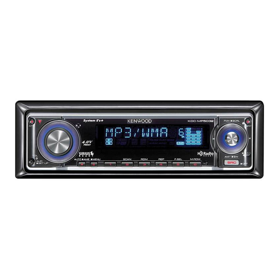
KDC-MP5032
SERVICE MANUAL
DC cord
(E30-6428-05)
Carrying case
(W01-1661-05)
Lever
(D10-4589-04) x2
CD MECHANISM EXTENSIONCORD (24P) : W05-0934-00
TDF PANEL INFORMATION
MODEL
KDC-MP5032
Panel assy
(A64-3733-02)
Remote controller assy
(A70-2067-15)
RC-527
Escutcheon
(B07-3125-01)
Screw set
(N99-1758-05)
© 2005-12 PRINTED IN JAPAN
B53-0364-00 ( N ) 589
TDF PANEL No.
TDF NAME
Y33-2430-62
TDF-MP65DB
SIZE AA BATTERY
(Not supplied)
Mounting hardware assy
(J21-9716-03)
Tapping screw
(N09-6280-05)
This product uses Lead Free solder.
Advertisement
Table of Contents

Related Manuals for Kenwood KDC-MP5032


Summary of Contents for Kenwood KDC-MP5032
- Page 1 CD RECEIVER KDC-MP5032 SERVICE MANUAL © 2005-12 PRINTED IN JAPAN B53-0364-00 ( N ) 589 CD MECHANISM EXTENSIONCORD (24P) : W05-0934-00 TDF PANEL INFORMATION MODEL TDF PANEL No. TDF NAME KDC-MP5032 Y33-2430-62 TDF-MP65DB Panel assy (A64-3733-02) DC cord Remote controller assy...
-
Page 2: Block Diagram
KDC-MP5032 BLOCK DIAGRAM (X34- ) CD5V SERVO+B BU5V PW-IC SVR LX-BUS CD MECHA OPELDISP PW-IC SP-OUT AM+B MARINEDISP DXM6580W IC11 PHONE PHONE PRE-OUT(4V) Q400-405 Q108 E-VOL FRONT PRE-OUT IC2-6 REAR DIMMER DIMMER MUTE PRE+B SUB-WOOFER IC11 3.3VREF. Q112 4VPRE-REF. MUTE... -
Page 3: Components Description
KDC-MP5032 COMPONENTS DESCRIPTION ELECTRIC UNIT (X34-3420-15) Ref. No. Application / Function Operation / Condition / Compatibility System µ-com E-vol IC Regulator IC for A8V Power IC Regulator IC for ILL+B (10.65V) Logic IC for muting Reset IC Motor Driver IC for Slide panel mecha... - Page 4 KDC-MP5032 COMPONENTS DESCRIPTION SWITCH UNIT (X16-2920-13) Ref. No. Application / Function Operation / Condition / Compatibility VFD Driver Remote Control IC The power supply of IC2 is turned on when Q1’s base level goes “L”. The power supply of filament is turned on when Q3’s base level goes...
-
Page 5: Microcomputer's Terminal Description
KDC-MP5032 MICROCOMPUTER’S TERMINAL DESCRIPTION SYSTEM MICROCOMPUTER : 30624MPGA77GP (X34 : IC1) Module Truth Pin No. Pin Name Application Processing Operation Description (functional) Value Table REMO EXTRA Remote controller signal input Pulse width is detected. LX_MUTE LX_M Mute request from slave unit... - Page 6 KDC-MP5032 MICROCOMPUTER’S TERMINAL DESCRIPTION Module Truth Pin No. Pin Name Application Processing Operation Description (functional) Value Table PM_CLOSE P-MECHA Panel mechanism close detection Refer to truth value table. ROMCOR_DET EXTRA E2PROM write request H : Writing PM_DET P-MECHA Panel mechanism detection...
- Page 7 KDC-MP5032 MICROCOMPUTER’S TERMINAL DESCRIPTION Module Truth Pin No. Pin Name Application Processing Operation Description (functional) Value Table When CD MUTE R is L : H (When CD) MUTE_PRE_R AUDIO O PRE_OUT MUTE Rch At momentary power down : H Only with 2-zone and NAVI interruption : L-fixed...
- Page 8 KDC-MP5032 MICROCOMPUTER’S TERMINAL DESCRIPTION MECHANISM MICROCOMPUTER : 703030BYGCJ21A (X32 : IC4) Processing Operation Pin No. Pin Name Application Remarks Description Not used. Low-fixed E2P SCL Rom correction E2P I2C clock Not used. Low-fixed 5V electric potential GND electric potential Not used.
- Page 9 KDC-MP5032 MICROCOMPUTER’S TERMINAL DESCRIPTION Processing Operation Pin No. Pin Name Application Remarks Description 41,42 Not used. Low-fixed 3.3V driven Multiplex RD signal 3.3V driven ASTB Multiplex ASTB signal 3.3V driven Not used. Low-fixed 3.3V driven Not used. Low-fixed 3.3V driven...
-
Page 10: Test Mode
KDC-MP5032 TEST MODE How to enter the test mode AAC disk, which contain 8 files or less, the first track and In order to enter the test mode, reset the unit while simulta- the following tracks are played in order. - Page 11 KDC-MP5032 TEST MODE Special display when all lights are on (The initial value is 0) • Using the VOL knob and [ ] / [ ] key, the HPF Front / When all lights are on with the STANDBY source, the follow- Rear can be adjusted in 2 steps : Through ↔...
- Page 12 KDC-MP5032 TEST MODE AUDIO data initialization Displays CD ejection error data. (Display) AUD_INIT [switched by [ ] / [ ] keys] (Display) EJERR1 : xx ↔ EJERR2 : xx ↔ EJERR3 : xx Key pressed briefly: Forced Power OFF data displayed.
- Page 13 KDC-MP5032 TEST MODE Fluorescent tube (ED1) short-checking 1. While pressing and holding the [Q] key and the [ATT] key, During STANDBY sourcing, each time [ATT] key is short- reset-start to start backup/installer, memory data, and CD pressed, the processing is switched in the following order.
-
Page 14: Dc Offset Error
KDC-MP5032 TEST MODE Method of clearing the programmable security 3. While the error conditions are being displayed, press [AUTO] code key for less than 1 second to clear the detection informa- tion. (E2PROM clear) 1. While “– – – –” is being displayed, press [ ] key for at 4. -
Page 15: Cd Load Error Detection
KDC-MP5032 DC OFFSET ERROR Cancel Condition Other • Press the Reset terminal on the main body. or set Backup • Function for checking and clearing data in E2PROM by a to OFF (Unplug and plug back in the DC connector). -
Page 16: Cd Eject Error Detection
KDC-MP5032 CD EJECT ERROR DETECTION Overview Operation Record the number of times when mechanism error (SW er- EJECT ror) occurred at CD EJECT. EJECT error recording shall be done in 4 patterns, by the SW (LOS SW) status illustrated below (3 patterns in models other than TYPE-... -
Page 17: Installer Memory Specifications
KDC-MP5032 INSTALLER MEMORY SPECIFICATIONS At specialists (or specialty stores), when the installer sends only one setting can be saved as the installer memory speci- the vehicle back to the user, they may make the store-recom- fication, and the source in which the saving operation was mended audio configuration. -
Page 18: Pc Board (Component Side View)
KDC-MP5032 PC BOARD (COMPONENT SIDE VIEW) ELECTRIC UNIT X34-3420-15 (J76-0049-22) 13 11 12 8 4 3 9 10 6 D501 C529 R503 C501 R507 C510 R933 C511 C512 L301 C502 C959 IC902 C958 D904 W127 C428 R936 C954 C504 C503... - Page 19 KDC-MP5032 D101 R105 R126 C105 C108 R112 R108 D111 R128 C104 R503 Q102 R109 Q112 R111 D103 C501 D110 D108 D107 C106 C102 EB EB R123 Q104 R114 R125 R117 Q105 R124 C107 R113 C103 Q111 R122 R938 R118 R116...
- Page 20 KDC-MP5032 PC BOARD (FOIL SIDE VIEW) ELECTRIC UNIT X34-3420-15 (J76-0049-22) R950 R104 R107 R952 R951 R945 R947 R937 R927 R935 C957 R924 D903 R921 R427 R920 R432 R431 W104 R261 R129 R203 R259 R932 D516 R520 C209 C203 R260 R521...
- Page 21 KDC-MP5032 R950 D408 C429 R952 R425 R951 R945 R948 C427 C426 D405 R946 Q300 R944 R427 R431 Q301 W123 X34-3420-15 Ref. No. Address C438 R401 R434 Q101 D412 Q103 Q114 Q300 Q301 R335 R307 R309 D305 R314 C326 Refer to the schematic diagram for the values of resistors and...
- Page 22 KDC-MP5032 PC BOARD (COMPONENT SIDE VIEW) CD PLAYER UNIT X32-5860-00 (J76-0212-02) CP27 IC11 R150 X32-5860-00 Ref. No. Address IC11 Refer to the schematic diagram for the values of resistors and capacitors.
- Page 23 KDC-MP5032 PC BOARD (FOIL SIDE VIEW) CD PLAYER UNIT X32-5860-00 (J76-0212-02) 12EJE-SW CP28 A3.3V REFOUTSV SHOCK LOS-SW LOCK DOUT ADIN HOLD F- F+ DOUT DGND R152 C100 R104 CP11 CP10 S7.5V BU5V SGND TYPE LOE/LIM PON2 PON1 SPD+ DMUTE BU3.3V...
- Page 24 KDC-MP5032 PC BOARD (COMPONENT SIDE VIEW) (FOIL SIDE VIEW) SWITCH UNIT SWITCH UNIT X16-2920-13 (J76-0050-12) X16-2920-13 (J76-0050-12) X16-2920-13 X16-2920-13 Ref. No. Address Ref. No. Address PAN5 REMO ROT-A ROT-B Refer to the schematic diagram for the values of resistors and...
- Page 25 KDC-MP5032 BU5V,B R519 TP27 (X34-3420-15) W104 C513 R403 C417 0.01 MUTE DRIVER R419 180 22u16 TP87 PRN-FL TP88 W121 Q116 4.7K R418 180 TP89 Q401 D514 MUTE 5.6V D511 D513 Q400 4.7K Q115 D515 TP83 R402 C418 8.0V R417 180...
- Page 26 KDC-MP5032 4V PRE+BSHORT PROTECTION BU5V,BU,8V Q15,16 4V PRE+B Q108 4V PRE+B SHORT PROTECTION TP27 W104 SMALL DET SW R505 5.6V IC11 C501 Q111 5.6V 4V PRE R946 D502 TP129 R123 SURGE DET R948 R949 R950 5.6V POWER 8.0V R428 R427...
- Page 27 • DC voltages are as measured with R213 1K ILL+B a high impedance voltmeter. Val- TP131 0.47u50 ues may vary slightly due to varia- ILL+B tions between individual instru- 1.2V ments or/and units. REGULATOR 10.7V ILL+B (10.65V) 14.4V TP25 KDC-MP5032 (1/2) X34-3420-15 (3/3)
- Page 28 KDC-MP5032 (X16-2920-13) TP30 (X16-2570-10) TP13 TP12 RST 14 RESET R6 470 TP11 R5 470 TP10 R4 470 X34- SYS DATA SYS DATA R3 470 R2 470 PAN DATA PAN DATA FL+SW REMO REMO RTRY CCW RTRY CCW RTRY CW RTRY CW...
- Page 29 KDC-MP5032 (2/2) (1G) CAUTION : For continued safety, replace safety critical components only with manufacturer's recommended parts (refer to parts list). Indicates safety critical components. To reduce the risk of electric shock, leakage-current or resistance measurements shall be carried out (exposed parts are acceptably insulated from the supply circuit) before the appliance is returned to the customer.
- Page 30 KDC-MP5032 (X32-586x-xx) IC1 : TAR5S33-F IC7 : UPD63763CGJ : DAP202U IC2 : NJM4580V-ZB IC9 : BR24L02FV-W UNIT DESTINATION IC3 : BA5824FP IC11 : TC7SET32FU-F 2SA1576A 0-00 IC4 : 703030BYGCJ21A : 2SB0970 K/M/E 0-02 IC5 : XC6219B332MR Q5,7 : DTA143XUA 0-01...
- Page 31 KDC-MP5032 LOADING & SLED SPINDLE (X92- ) MOTOR (X92- ) MOTOR SIGNAL LINE NATION GND LINE B LINE 4ch BTL 2.4-4.2V 2.6-4.2V DRIVER 2.4-4.2V 2.6-4.2V TP26 TP31 S7.5V SLD+ SPD+ 1.2-5.5V 1.0-5.0V SLD+ SPD+ TP28 TP33 SLD- SPD- 1.2-5.5V 1.0-5.0V...
- Page 32 KDC-MP5032 EXPLODED VIEW (CD MECHANISM) DPU1 DFPC1 (X32) : N09-4460-15 : N09-6317-05 : N09-6004-15 : N09-6007-15 : N09-6051-15 : N19-2163-04 : N39-2020-46 : N09-6108-15 : N09-6155-15 Parts with the exploded numbers larger than 700 are not supplied.
-
Page 33: Exploded View (Unit)
KDC-MP5032 EXPLODED VIEW (UNIT) SIZE AA BATTERY (X34) (Not supplied) M2x2 : N09-6269-05 M2x2.5 : N09-6326-05 DME1 M1.7x2 : N09-6140-05 M2.6x6 : N78-2660-48 φ2x6 M2x2 : N09-6141-05 : N80-2006-48 φ2x8 M2x2.5 : N09-6142-05 : N80-2008-43 φ1.7x4.5 φ3x5 : N09-6190-05 : N83-3005-48 φ3.05x5.83... -
Page 34: Parts List
KDC-MP5032 PARTS LIST New parts Parts without Parts No. are not supplied. Les articles non mentionnes dans le Parts No. ne sont pas fournis. Teile ohne Parts No. werden nicht geliefert. Desti- Desti- Ref. No. Parts No. Description Ref. No. - Page 35 KDC-MP5032 PARTS LIST SWITCH UNIT (X16-2920-13) Desti- Desti- Ref. No. Parts No. Description Ref. No. Parts No. Description nation nation RK74HB1J102J CHIP-COM 1.0K J 1/16W CK73GB1A105K CHIP C 1.0UF RK73EB2E101J CHIP R J 1/4W CK73GB1H104K CHIP C 0.10UF R2-6 RK73EB2E471J...
- Page 36 KDC-MP5032 PARTS LIST CD PLAYER UNIT (X32-5860-00) Desti- Desti- Ref. No. Parts No. Description Ref. No. Parts No. Description nation nation CP27 RK74GB1J472J CHIP-COM 4.7K J 1/16W NJM4580V-ZB ANALOGUE IC CP28 RK74GB1J103J CHIP-COM 10K J 1/16W BA5824FP ANALOGUE IC R1,2...
- Page 37 KDC-MP5032 PARTS LIST ELECTRIC UNIT (X34-3420-15) Desti- Desti- Ref. No. Parts No. Description Ref. No. Parts No. Description nation nation C326 CC73GCH1H101J CHIP C 100PF CP206 RK74GB1J222J CHIP-COM 2.2K J 1/16W C401 CD04AS1C470M ELECTRO 47UF 16WV CP207,208 RK74GA1J102J CHIP-COM 1.0K...
- Page 38 KDC-MP5032 PARTS LIST ELECTRIC UNIT (X34-3420-15) Desti- Desti- Ref. No. Parts No. Description Ref. No. Parts No. Description nation nation R212 RK73GB2A473J CHIP R J 1/10W R408,409 RK73GB2A223J CHIP R J 1/10W R213 RK73GB2A102J CHIP R 1.0K J 1/10W R410,411...
- Page 39 KDC-MP5032 PARTS LIST ELECTRIC UNIT (X34-3420-15) Desti- Desti- Ref. No. Parts No. Description Ref. No. Parts No. Description nation nation W124 R92-1252-05 CHIP R 0 OHM J 1/16W UMC2N TRANSISTOR W125,126 R92-2053-05 CHIP R 0 OHM J 1/8W 2SB1565 TRANSISTOR...
- Page 40 KDC-MP5032 PARTS LIST CD MECHANISM (X92-5470-00) (DXM-6680W) Desti- Desti- Ref. No. Parts No. Description Ref. No. Parts No. Description nation nation D13-2157-04 GEAR D13-2158-04 GEAR D13-2168-04 GEAR D13-2171-04 GEAR D13-2381-13 RACK (GEAR) D14-0759-04 ROLLER D21-2382-04 SHAFT D23-0954-04 RETAINER D39-0246-05 DAMPER...
- Page 41 KDC-MP5032 CAPACITORS 2 2 0 • Capacitor value CC45 Color* 010 = 1pF 0 = 22pF 1 = Type ... ceramic, electrolytic, etc. 4 = Voltage rating 100 = 10pF 2 = Shape ... round, square, etc. 5 = Value...
-
Page 42: Specifications
Installation Size (W x H x D) ................182 x 53 x 155mm ....................... 7-3/16 x 2-1/16 x 6-1/8inch Weight ........................3.1lbs (1.40kg) KENWOOD follows a policy of continuous advancements in development. For this reason specifications may be changed without notice.
Need help?
Do you have a question about the KDC-MP5032 and is the answer not in the manual?
Questions and answers