Advertisement
Quick Links
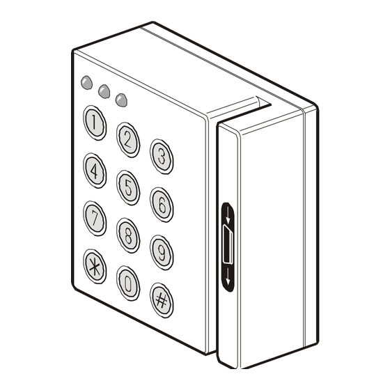
3-LED Keypad
3-LED Keypad with
Card Reader
3-LED Keypad / 3-LED Keypad with Card Reader
M
OUNTING THE UNIT
1. Remove the Allen screw from the reader's mounting
plate to open the reader. (Fig. 3)
2. Use the mounting plate as a template to mark the screw
hole locations on the wall. (Fig. 4)
3. Run the cable through the rubber gasket (gasket is
used for outdoors installation) and then through the hole
in the mounting plate.
4. Fasten the mounting plate to the wall.
5. Connect the cable to the terminal block (Fig. 5).
6. Set the RAS address DIP switch (Fig. 6).
7. Check the jumper position for the heater is 'ON' for
outdoors installation, and 'OFF' for indoors (Fig. 5).
8. Place the spring on the back tamper switch. (Fig. 4).
9. Slide the reader onto the mounting plate and close the
unit with the Allen screw (reverse order of Fig. 3, and
then follow Fig. 8).
C
ONNECTING CONTROL PANEL TO KEYPAD
Refer to the ATS control panel installation guide for instructions.
Each reader has a cover tamper.
Note: Figures and instructions also apply to the
ATS1151 unless stated otherwise.
S
AFETY INSTRUCTIONS
•
Always observe the safety regulations applicable in
your country. Read the following safety instructions
before attempting to install the product.
•
Before disassembling the product, disconnect the
power supply unit from the controller.
•
Only connect the mains to the power supply unit when
all installation procedures have been completed.
•
Never cover the power supply unit as it may overheat.
•
When installing, do not force any parts or screws.
E
XTRA NOTES FOR INSTALLING A KEYPAD OUTDOORS
(
. 2)
FIG
1. Install a rain protection hood over the reader.
Description
Connection
12V
Power supply
0V Connection to reader
Data + connection to
reader
Data - connection to
reader
Request to exit button
Open collector output
50mA max.
2. Mount the rubber gasket (supplied) between the unit
3. Set the jumper J4 (Fig. 5) to the 'ON' position to enable
4. If a motorised lock or gate is used, mount the reader a
C
ABLE ENTRY AND CONNECTIONS
1. RAS DIP switches
2. Terminal block: +12 V
3. Buzzer
4. Heater jumper
5. Term link
C
ONNECTIONS TERMINALS
PWR
(
. 3)
FIG
GND
D+
D -
IN
OUT
L
INKS
TERM
© 2003 GE Interlogix B.V.
All rights reserved
3-LED Keypad with Card Reader
ATS1151/1156 ATS2000/3000/4000
Power
GND
D+
D-
IN
OUT
Reader connection to the ATS panels
and the wall to seal the unit.
the heater (top two pins).
few metres away from the door so the lock or gate has
enough space to open fully.
(
FIG
Power supply. If the distance between the arming
station and the control panel does not exceed
100m, then the arming station can be
powered using the Comms + and – from the
control panel. Otherwise use AUX PWR from
DGP's or an auxiliary power supply.
Data positive and data negative connection of the
databus.
Remote units can be up to 1.5 km from the ATS
control panel.
A request to exit button (normally open,
momentary push-button switch) can be connected
across "IN" and "-". When pressed, this button
controls the request to exit function.
Open collector output, 50 mA maximum. It is the
first output of the output control group that is
assigned to this arming station.
(
5)
FIG
Fitted if this device is the last device on the
system databus. For more details see the ATS
control panel installation guide.
ATS1151
3-LED Keypad
ATS1156
ATS1250
Comms
Comms
12V
12V
0V
0V
D+
D+
D-
D-
-
-
-
-
(
. 5)
FIG
. 5)
MAINST-ATS1151/6
03/2004
Advertisement

Related Manuals for GE Interlogix ATS1151

Summary of Contents for GE Interlogix ATS1151
- Page 1 DGP’s or an auxiliary power supply. Data positive and data negative connection of the Note: Figures and instructions also apply to the databus. ATS1151 unless stated otherwise. Remote units can be up to 1.5 km from the ATS AFETY INSTRUCTIONS control panel.
-
Page 2: Technical Data
Current consumption 45 mA Dimensions in mm (H x W x D) (ATS1156) 96 x 96 x 40 Dimensions in mm (H x W x D) (ATS1151) 96 x 67 x 28 Operating temperature -25°C to +70°C Humidity Non condensing... - Page 3 1200 mm 1200 mm Heater Term PWR GND D+ D– OUT IN...
- Page 4 RAS 2 RAS 3 RAS 4 RAS 1 Heater RAS 5 RAS 6 RAS 7 RAS 8 RAS 9 RAS 10 RAS 11 RAS 12 Term PWR GND D+ D– OUT IN RAS 13 RAS 14 RAS 15 RAS 16 To controller LED 1 LED 2...
Need help?
Do you have a question about the ATS1151 and is the answer not in the manual?
Questions and answers