
Subscribe to Our Youtube Channel
Related Manuals for Kenwood TK-D740HV


Summary of Contents for Kenwood TK-D740HV
- Page 1 TK-D740 TK-D740H TK-D740HV TK-D840 TK-D840H TK-D840HU VHF DIGITAL TRANSCEIVER UHF DIGITAL TRANSCEIVER USER MANUAL B5A‑0925‑00/01...
-
Page 2: Table Of Contents
Contents PREPARATION ........................4 Connecting the power cable.................... 4 Installing the Transceiver ....................4 ORIENTATION ........................6 FRONT AND REAR VIEWS ....................6 DISPLAY ..........................8 PROGRAMMABLE FUNCTIONS ..................11 BASIC OPERATION ......................15 SWITCHING POWER ON/ OFF ..................15 Transceiver Password .................... - Page 3 ADVANCED OPERATIONS ....................20 EMERGENCY CALLS ...................... 20 Lone Worker Mode ......................20 SCRAMBLER ........................21 MONITOR/ SQUELCH OFF ..................... 21 Squelch Level ........................ 22 PUBLIC ADDRESS (PA) ....................22 HORN ALERT ........................22 GPS REPORT ........................22 DMR ............................. 23 INDIVIDUAL/GROUP CALLS ...................
-
Page 4: Preparation
PREPARATION WARNING Various electronic equipment in your vehicle may malfunction if they are not properly protected from the radio frequency energy which is present while transmitting. Typical examples include electronic fuel injection, anti-skid braking, and cruise control. If your vehicle contains such equipment, consult the dealer for the make of vehicle and enlist his/her aid in determining if they will perform normally while transmitting. - Page 5 3 Slide the transceiver into the mounting bracket and secure it using the supplied hex-headed screws. 4 Mount the microphone hanger in a location where it will be within easy reach of the user. • The microphone and microphone cable should be mounted in a place where they will not interfere with the safe operation of the vehicle.
-
Page 6: Orientation
ORIENTATION FRONT AND REAR VIEWS ACC. (Power) switch Press to switch the transceiver ON or OFF. keys Press to activate their programmable functions. Display Refer to page 8. keys Press to activate their programmable functions. TX/RX Indicator Lights red while transmitting. Lights green while receiving a signal. Flashes orange when receiving an optional signaling call. -
Page 7: Antenna Connector
Antenna connector Connect the antenna to this connector. ACC connector Connect the ACC to this connector, via the KCT-60. External speaker jack Connect an external speaker to this jack. Power input connector Connect the DC Power Cable to this connector. -
Page 8: Display
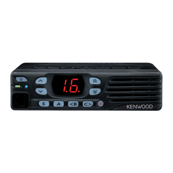
DISPLAY The display shows the zone/ channel number and the left and right dots show various modes of operation. Display Description Zone Display (Zone 1) Channel Display (Channel 16) Appears during Scan. (Sc) Appears during the transceiver is stunned. (St) Appears when switch the transceiver ON. - Page 9 Display Description Appears during Send Data. (dt) Appears during the channel is busy. The selected channel is the Priority channel 1. (P1) The selected channel is the Priority channel 2. (P2) The selected channels are the Priority channel 1 and 2. (PP) Appears when the Scrambler function is activated.
- Page 10 modes of operation, as listed below. • • External Speaker • Horn Alert • Lone Worker • Public Address • Scan Delete/Add • Scrambler • Talk Around • Priority Channel The right dot will blink during special operations, as listed below. •...
-
Page 11: Programmable Functions
PROGRAMMABLE FUNCTIONS , S, A, <B, C>, and The , , keys can be programmed with the functions listed below. Ask your dealer for details on these functions. Note: ◆ The duration of pressing a key to activate a function is dependent on your dealer setting. -
Page 12: Home Channel
n Emergency Places the transceiver into Emergency mode. Emergency mode is used to carry out emergency actions. Note: ◆ This function can be programmed only on the key. n Home Channel Press this key to immediately select your home channel. n Home Channel Select Hold down this key to set the current channel as the Home Channel. -
Page 13: Squelch Off
Code mode, to change the Privacy List number. Hold the key again exit Scrambler Code mode. Additionally, the Privacy List becomes the Scrambler List. Note: ◆ This function cannot be used in certain countries. Contact your KENWOOD dealer for further information. n Send the GPS data Manually sends your GPS data to the base station. - Page 14 n Zone Delete/Add Toggles the Zone status between deleted and added. n Zone Down Decreases the zone number in steps of 1. n Zone Down (Continuous) Hold down this key to continuously decrease the Zone number. n Zone Up Increases the zone number in steps of 1. n Zone Up (Continuous) Hold down this key to continuously increase the Zone number.
-
Page 15: Basic Operation
BASIC OPERATION SWITCHING POWER ON/ OFF Press [ ] to switch the transceiver ON. Press [ ] again to switch the transceiver OFF. Transceiver Password If the Transceiver Password function is programmed, “PS” will appear on the display when the power is turned ON. To enter the password: 1 Press to select a digit. -
Page 16: Receiving
RECEIVING Select the desired zone and channel. If signaling has been programmed on the selected channel, you will hear a call only if the received signal matches your transceiver settings. Receiving Group Calls When you receive a group call and the received group ID matches the ID set up on your transceiver, you can hear the caller’s voice. -
Page 17: Fleetsync: Alphanumeric 2-Way Paging Function
FleetSync: ALPHANUMERIC 2-WAY PAGING FUNCTION FleetSync is an Alphanumeric 2-way Paging Function and is a protocol owned by JVC KENWOOD Corporation. SELCALL (SELECTIVE CALLING) A Selcall is a voice call to a particular station or to a group of stations. -
Page 18: Scan
SCAN Scan monitors for signals on the transceiver channels. While scanning, the transceiver checks for a signal on each channel and only stops if a matching signal is present. To start/ stop scanning, press the key programmed as [Scan]. • “Sc”... -
Page 19: Dtmf Calls
DTMF CALLS Note: ◆ For keypad operation, you must use an optional microphone with a keypad. MANUAL DIALING 1 Press and hold the PTT switch. 2 Enter the desired digits using the keypad. • If Keypad Auto-PTT is enabled by your dealer, you do not need to press the PTT switch to transmit;... -
Page 20: Advanced Operations
ADVANCED OPERATIONS EMERGENCY CALLS If your transceiver has been programmed with the Emergency function, you can make emergency calls. 1 Press and hold the key programmed as [Emergency]. • Ask your dealer for the length of time necessary to hold this key before the transceiver enters Emergency mode. -
Page 21: Scrambler
SCRAMBLER The Scrambler function allows you to hold a conversation in complete privacy. When activated, any other party listening in on your channel will be unable to understand your conversation. Press this key to toggle the Scrambler function ON or OFF. Press the key programmed as [Scrambler] to toggle the Scrambler function ON or OFF. -
Page 22: Squelch Level
Squelch Level If a key has been programmed as [Squelch Level], you can readjust your transceiver’s squelch level: 1 Press the key programmed as [Squelch Level]. • “SL” appears on the display, followed by the current squelch level. 2 Press to select the desired squelch level from 0 to 9. -
Page 23: Dmr
DMR is a generic name for a digital communication system protocol utilizing 4-level FSK. In a DMR Conventional system, communications are realized by sending and receiving digital signals on a DMR digital channel. Using a DMR ID (Unit ID or Group ID) allows the various communications INDIVIDUAL/GROUP CALLS Each channel is set up with an individual or group ID list number. -
Page 24: Background Operations
BACKGROUND OPERATIONS TIME-OUT TIMER (TOT) The Time-out Timer is used to prevent you from using a channel for an extended duration. If you continuously transmit for a preset time, the transceiver will stop transmitting and a warning tone will sound. Release the PTT switch to stop the tone. -
Page 25: Ptt Id
PTT ID PTT ID is the transceiver unique ID code which is sent each time the PTT switch is pressed and/or released. Note: ◆ PTT ID can be made only in analog operation. SIGNALING QT/ DQT The Encoder/Decoder function uses QT/ DQT to segregate talk groups, so users only hear calls from their own group. - Page 26 © 2016...
Need help?
Do you have a question about the TK-D740HV and is the answer not in the manual?
Questions and answers