Table of Contents
Advertisement
NK105G2
HD Series Manual
Techno CNC Systems, LLC ©2016 (05/02/17)
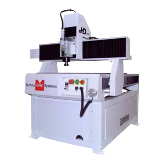
This document will provide a quick guide to the set up and operation of the Techno HD Mini and
Techno HD Series CNC routers equipped with the NCstudio controller.
The HD Series and HD Mini CNC routers are powered by high precision, stepper motors and
controlled by a hand-held NCstudio controller.
NCstudio Controller
Call: 1-631-648-7481 or Visit: support.technocnc.com
1
Advertisement
Table of Contents

Related Manuals for Techno CNC Systems NK105G2


Summary of Contents for Techno CNC Systems NK105G2
- Page 1 NK105G2 HD Series Manual Techno CNC Systems, LLC ©2016 (05/02/17) This document will provide a quick guide to the set up and operation of the Techno HD Mini and Techno HD Series CNC routers equipped with the NCstudio controller. The HD Series and HD Mini CNC routers are powered by high precision, stepper motors and controlled by a hand-held NCstudio controller.
-
Page 2: Table Of Contents
NK105G2 HD Series Manual TABLE OF CONTENTS Forklift Guide ............... Page 3 Safety Instructions ............... Page 4 Colleting Guidelines ............... Page 5 HD Mini Setup ........... Page 6 HD Mini Enabling the Machine ........... Page 7 HD Series Quick Setup ........... -
Page 3: Forklift Guide
NK105G2 HD Series Manual www.technocnc.com (HTT06081112) Tel: 631-648-7481 • Email: support@technocnc.com FORKLIFT GUIDE I. UNPACKING AND MACHINE IDENTIFICATIONS All Techno machines are shipped assembled and secured to a wooden pallet. Rear of Machine Unpack all items that shipped with your machine. Check the items against the packing slip to be sure nothing was left out. -
Page 4: Safety Instructions
NK105G2 HD Series Manual Safety Instructions READ THESE INSTRUCTIONS THOROUGHLY BEFORE OPERATING MACHINE. DO NOT OPERATE MACHINE IF YOU ARE UNFAMILIAR WITH THESE SAFE OPERATING INSTRUCTIONS. DO NOT OPERATE MACHINE WITHOUT KNOWING WHERE THE EMERGENCY STOP SWITCH IS LOCATED. WARNING: IMPROPER OR UNSAFE OPERATION OF THE MACHINE WILL RESULT IN PERSONAL INJURY AND/OR DAMAGE TO THE EQUIPMENT. -
Page 5: Colleting Guidelines
NK105G2 HD Series Manual WARNING! THE SPINDLE WILL BE DAMAGED IF UNBALANCED EQUIPMENT IS USED. AIR SUPPLY MUST BE FILTERED AND DRY. Call: 1-631-648-7481 or Visit: support.technocnc.com... -
Page 6: Hd Mini Setup
NK105G2 HD Series Manual I. TECHNO HD MINI SETUP Carefully remove the HD Mini from its crate. Be sure to remove the brackets from its four feet as well as anything stowed under the HD mini during shipping. Attached the provided leveling feet to the four legs and adjust accordingly until the table is level. -
Page 7: Hd Mini Enabling The Machine
NK105G2 HD Series Manual I. Enabling the HD Mini Control Panel Functions. Figure 1.4 shows the machine control panel buttons and functions. Fig. 1.4 Power Disable Emergency Stop Power Enable Spindle VFD Tool Port Readout Calibration Block 1.5 Enabling The Machine. -
Page 8: Hd Series Quick Setup
NK105G2 HD Series Manual I. TECHNO HD SERIES QUICK SETUP The Techno HD Series Router is powered by 220 Volt AC. Unless specially requested, the electronics require 3-phase power. Unpack the hand- The Electronics are housed in the large NEMA enclosure held controller as shown in Figure 1.1. -
Page 9: I.ihd Series Installation
NK105G2 HD Series Manual I.I Techno HD Installation Fig.1.1 Carefully remove the HD from its wood pallet. Be sure to remove the brackets from its four feet as well as anything stowed under the HD during shipping. Remove all bubble wrap, foam and strapping from the machine. - Page 10 NK105G2 HD Series Manual Open the back of the controller box (shown in Fig 1.2a) with the key provided. The electronics will now be exposed and components identified in Fig 1.2b. A- Controller Board. B- 24Volt PSU. C- Stepper Driver. D- 220Volt In. Fig. 1.2b Fig. 1.2a Take the black connector coming from the Hand- held controller (fig 1.3a,) and guide it through...
- Page 11 NK105G2 HD Series Manual Have a qualified electrician attach 220 Volts to the terminal on the bottom of the box (Fig 1.4.) Unless specifically requested by the user, 3 Phase 220 Volt is needed. If the machine has been modified for single phase operation, then L1, L3 and GND are used, and nothing is attached to L2. Fig. 1.4...
-
Page 12: Vacuum Pump Installation
NK105G2 HD Series Manual II. Vacuum Pump Installation WARNING: Direction of Pump Rotation is critical. Briefly start Pump and check rotation (arrow on casing). Exchange phases if rotation is incorrect. IF YOU RUN THE PUMP/BLOWER CONTINUOUSLY IN THE WRONG DIRECTION, THE VANES WILL BE DAMAGED. Use the... -
Page 13: Hd Series Enabling The Machine
NK105G2 HD Series Manual II. Enabling the HD Series Control Panel Functions. Figure 2.1b shows the buttons and their functions. IMPORTANT: DOORS MUST BE CLOSED FOR POWER TO ENABLE. Fig. 2.1b Power Vacuum Emergency Disable Controls Stop Power Spindle Inverter... -
Page 14: Ii.ihd Series / Hd Mini Start Up
NK105G2 HD Series Manual II.I HD Series / HD Mini Start-Up When the machine first powers on, the display on the controller will light up and say “Starting System”. (Fig. 3.1a) Once the system has booted it will ask the user “Back to refer- ence point?”... -
Page 15: Functions Of The Keys
NK105G2 HD Series Manual Single Keystroke Functions on the Handheld Pendant Bold Indicates Primary Function Y+ Movement Positive Feedrate (Input the number 8) Override (Parenthesis Indicates Secondary Function) (Input the number 7) Z+ Movement (Input the number 9) X- Movement... -
Page 16: Shift Commands / Combination Keystrokes
NK105G2 HD Series Manual Shift Commands / Combination Keystrokes To use the shift commands, you must press and hold the shift key and then select a second key to use the Shift Command function. Increase spindle RPM Switch between work (relative) and machine (absolute) -
Page 17: Operating Tutorials
NK105G2 HD Series Manual III Operating Tutorials. 3.0- Switching Movement to Step or Jog. There are two modes that allow the user to control the movement of the machine: Jog and Step. To switch between these modes press the “Shift” button. -
Page 18: Modifying The Jog Speed And Step Size
NK105G2 HD Series Manual 3.3- Modifying the Jog Speed and Step Size The machine can be jogged at two speeds, low and high. You can also change the increments in which the machine will move in Step mode. These speeds are set in the Manual Parameters page. -
Page 19: Adjusting The Xyz Position/Wcs/User Origin
NK105G2 HD Series Manual 3.5- Adjusting the XYZ Zero position/WCS/User Origin. XYZ zero position, Working Coordinate System (WCS), and User Origin are all the same thing. Different CAM systems and users just name the concept differently. For convenience XYZ zero position will be used in the rest of this manual. -
Page 20: Loading A G-Code File
NK105G2 HD Series Manual 3.6- Loading a G-code File. Press the Menu button. Select “2.USB files” to access the flash drive. Only a G-code file with an “nc” extension with show. Scroll through the files with and Select file by pressing OK. Then load the file by pressing 1. Note: Files can be copied from this USB to the controller using the “2” button Local disk space is limited! Once a file is copied locally, it can also be selected from the jog speed /step size screen... -
Page 21: Running A G-Code File
NK105G2 HD Series Manual 3.7- Running a G-code file. Once the XYZ origin has been set as per section 3.4 and the file has been loaded as per section 3.6 the user is ready to run the G-code file. To run the G-code file simply press the start button Once the spindle has reached speed the machine will move into position to start the first cut. The file can be paused while running by pressing To resume the file press . To abort the file at any time press . Note: When the machine pauses, the spindle will stop and the Z axis will move to the Z clearance/ Safe height to allow inspection of the part. If the machine is jogged off the part during a pause, it will lose its position and when the file is resumed it will start from the new position. -
Page 22: Advanced Tutorials
NK105G2 HD Series Manual IV. Advanced Tutorials. 4.1- Alternating between Override and Programmed Feedrates. The controller can run G-code files with speed set by the user on the keypad, override speed, or with speed set in the CAM package/G-code file, programmed speeds. To determine what speed protocol will be used, do the following: In the main screen, press menu to enter the menu screen . 4. oper param... -
Page 23: Setting Override Speed For A G-Code File
NK105G2 HD Series Manual 4.2 Setting the Override Speed for a G-code file. From the main screen, press Menu to access the Menu screen. Use the arrow keys to move the cursor and highlight 4. oper param Press OK to select this option and enter the Operations Parameters screen Use the arrow keys to move between each option and press enter to select the option. -
Page 24: Setting The Table Size
NK105G2 HD Series Manual 4.3 Setting the Table Size. From the main screen, press Menu to access the Menu screen. Use the arrow keys to move the cursor and highlight 5. MFR param Press OK to select. Password: 33587550 The MFR parameters screen will now open. -
Page 25: Changing To Different Offset (A New Xy Zero Location)
NK105G2 HD Series Manual Press Menu Operations Select WSC Origin 1 Origin 2 . . . Call: 1-631-648-7481 or Visit: support.technocnc.com... -
Page 26: Notes On The G-Code File Acceleration Set
NK105G2 HD Series Manual Notes On the G-code File If a part requires multiple tools, it is best to output a different file for each part. If the G-code file references a tool number higher than T10, then the controller will give an error at the start of the file. M6 T1 to M6 T10 are allowed. In general it is best to remove T commands by telling the CAM package that the machine is not a tool changer machine, or insuring that the Tool number does not exceed 10. -
Page 27: Appendix
NK105G2 HD Series Manual V. Appendix HD Settings HD Settings High/Low Speeds and Step Distances (from main screen, press ‘OK’) MSpd: 800 / 100 Step XY: 0.005 Step Z: 0.005 File: (active file name) Note: These numbers can vary. All following settings can be found by pressing the ‘Menu’ key and are worded/abbreviated as you would see them on screen. - Page 28 NK105G2 HD Series Manual Settings (continued) Park Mode Not Move To Park Site To WCS Origin Park Site 1. Input Site Input Park Site X: _____ Y: _____ Z: _____ 2. Select Site Select Current Position As Park Pos by [OK] Key Return ny [ESC] Key 6.
- Page 29 NK105G2 HD Series Manual Settings (continued) 0 ms S-Off in Intev 7. G73-G83 Retract 0.0 inch 8. Ignore F Code 9. Ignore S Code 10. Spindle Stop S off at Pause* S off at Stop* S off at End 11.
- Page 30 NK105G2 HD Series Manual Settings (continued) Current Tool No Tool Offset 1. Tool 1 X: _____ Y: _____ Z: _____ (settings repeat through tool 10) 15. ENG Unit 5. MFR Param PASSWORD: 33587550 1. Velocity Decel Dist 0.394 inch Approach Speed 25.00 in/min...
- Page 31 NK105G2 HD Series Manual Settings (continued) 4. Machine Stroke Strk Upper Lmt varies depending on machine size Strk Lower Lmt varies depending on machine size 5. Ref Point Set RefP Speed X: 70 in/min Y: 70 in/min...
- Page 32 NK105G2 HD Series Manual Settings (continued) 0.291 rad/s Rotary Y Acc 6.98 rad/s^2 Max Rotary Vel 30 r/min 8. Backlash Set Compensation on Axis Backlash * X: 0.0 Y: 0.0 Z: 0.0 9. Calib Thickness 1.587 inch (will vary slightly) 10.
- Page 33 NK105G2 HD Series Manual Settings (continued) English 2. Export Log 3. System Update 4. Register 5. Help Spec: Help Message Show Delay Value: 60 Unit: S 6. Reboot 7. Exit 8. Diagnosis System Info 1. Software Version 2. Card No 3.
-
Page 34: Hd Mini Tabletop Settings
NK105G2 HD Series Manual HD Mini Tabletop Settings Website:support.technocnc.com | Call: 631-648-7481 High/Low Speeds and Step Distances (from main screen, press ‘OK’) MSpd: 800 / 100 Step XY: 0.005 Step Z: 0.005 File: (active file name) Note: These numbers can vary. -
Page 35: Hd Mini Tabletop Settings
NK105G2 HD Series Manual HD Mini Tabletop Settings Website:support.technocnc.com | Call: 631-648-7481 Park Mode Not Move To Park Site To WCS Origin Park Site 1. Input Site Input Park Site X: _____ Y: _____ Z: _____ 2. Select Site Select Current Position As... - Page 36 NK105G2 HD Series Manual HD Mini Tabletop Settings Website:support.technocnc.com | Call: 631-648-7481 2. Y = 0.000 3. Z = 0.000 2. G55 — G59 1. X = 0.000 2. Y = 0.000 3. Z = -1.939 6. Cycle Process ...
- Page 37 NK105G2 HD Series Manual HD Mini Tabletop Settings Website:support.technocnc.com | Call: 631-648-7481 Tool Change Tip* Cycle Times* Deep Hole Mode* Retract Amount* 0.039 in Select Tool No* 14. PLT Params Lifting Height = 0.197 PLT Unit = 40.000 Tool Stop = 0.001 Process Depth = -0.039...
- Page 38 NK105G2 HD Series Manual HD Mini Tabletop Settings Website:support.technocnc.com | Call: 631-648-7481 100.00 in/sec^2 Jerk 300.00 in/sec^3 Max Speed of Z 125.00 in/min X/Y = 393.701 Short Seg Spd Lmt SPDLMT Length 0.1 inch Z down option = 0 Z Plunge Cut Spd 11.811 in/min...
- Page 39 NK105G2 HD Series Manual HD Mini Tabletop Settings Website:support.technocnc.com | Call: 631-648-7481 Strk Lower Lmt X: 0.000 Y: 0.000 Z: -3.937 6. Ref Point Set RefP Speed X: 70.866 in/min Y: 70.866 in/min Z: 59.005 in/min RefPDir...
- Page 40 NK105G2 HD Series Manual HD Mini Tabletop Settings Website:support.technocnc.com | Call: 631-648-7481 9. Backlash Set Compensation on Axis Backlash * X: 0.0 Y: 0.0 Z: 0.0 10. Calib Thickness 0.590 inch (will vary slightly) 11. Enable S Algo 12. Arc Incriment 12 ARadiu Tolerance = 0.079 in...
- Page 41 NK105G2 HD Series Manual HD Mini Tabletop Settings Website:support.technocnc.com | Call: 631-648-7481 1. Language Chinese English 2. Export Log 3. System Update 4. Register 5. Help Spec: Help Message Show Delay Value: 600 Unit: S 6. Reboot 7. Exit 8. Diagnosis System Info 1.
-
Page 42: Using The 4Th Axis On An Hd Machine
NK105G2 HD Series Manual Website:support.technocnc.com | Call: 631-648-7481 Using the 4 Axis on the Techno HD Series Machines Note: The 4 axis on the Techno HD series machine is not a true 4 axis. You can only use this to do “wrapping” tool paths. This means that the file is designed as a regular, flat, 3-axis file, which is scaled so that the width matches the circumference of round stock. -
Page 43: Using The 4Th Axis On An Hd Mini Machine
NK105G2 HD Series Manual Website:support.technocnc.com | Call: 631-648-7481 Using the 4 Axis on the Techno HD Mini Machines Note: The 4 axis on the Techno HD Mini machine is not a true 4 axis. You can only use this to do “wrapping”... -
Page 44: Hd Mini 4Th Axis Settings
NK105G2 HD Series Manual HD Mini 4th Axis Settings Website:support.technocnc.com | Call: 631-648-7481 High/Low Speeds and Step Distances (from main screen, press ‘OK’) MSpd: 800 / 100 Step XY: 0.005 Step Z: 0.005 File: (active file name) Note: These numbers can vary. - Page 45 NK105G2 HD Series Manual HD Mini 4th Axis Settings Website:support.technocnc.com | Call: 631-648-7481 Park Mode Not Move To Park Site To WCS Origin Park Site 1. Input Site Input Park Site X: _____ Y: _____ Z: _____ 2. Select Site...
- Page 46 NK105G2 HD Series Manual HD Mini 4th Axis Settings Website:support.technocnc.com | Call: 631-648-7481 Cycle Times Cycle Interval 0 ms S-Off in Intev 7. G73-G83 Retract 0.0 inch 8. Ignore F Code 9. Ignore S Code 10. Spindle Stop S off at Pause*...
- Page 47 NK105G2 HD Series Manual HD Mini 4th Axis Settings Website:support.technocnc.com | Call: 631-648-7481 Select Tool No* 14. Tool Change ATC Capacity* Current Tool No Tool Offset 1. Tool 1 X: _____ Y: _____ Z: _____ (settings repeat through tool 10) Tool Change Tip 15.
- Page 48 NK105G2 HD Series Manual HD Mini 4th Axis Settings Website:support.technocnc.com | Call: 631-648-7481 Y: Negative Z: Negative 3. Pulse Equiv * 0.005000 (Mini) 0.005000 (Mini) 0.002500 (Mini) 4. Machine Stroke Strk Upper Lmt X: 23.622 Y: 35.433 Z: 0.000 Strk Lower Lmt ...
- Page 49 NK105G2 HD Series Manual HD Mini 4th Axis Settings Website:support.technocnc.com | Call: 631-648-7481 0.006 deg/pulse MM as Unit Rev Work Radius 0.394 Rotary Takeoff 0.291 rad/s Rotary Y Acc 6.98 rad/s^2 Max Rotary Vel 30 r/min 8. Backlash Set Compensation on Axis Backlash *...
- Page 50 NK105G2 HD Series Manual HD Mini 4th Axis Settings Website:support.technocnc.com | Call: 631-648-7481 3. Factory Params 4. Export Params 5. Import Params 7. System Upkeep 1. Language Chinese English 2. Export Log 3. System Update 4. Register 5. Help Spec: Help Message Show Delay...
-
Page 51: Hd Mini Machine Lubrication
NK105G2 HD Series Manual VI. HD Mini Machine Lubrication. NOTE: AVOID A BUILD UP OF DEBRIS ON Lubricating the X Axis. MOVING PARTS. CLEAN OFF ANY DEBRIS TO To access the X axis ball screw and rails, you must remove the covers by taking off the AVOID DAMAGING THE MACHINE. - Page 52 NK105G2 HD Series Manual Lubricating the Y Axis. Lubricating the Z Axis. The Y axis ball screw is located under the To access the Z axis ball screw and machine. It can be accessed from the back rails, first jog the Z axis down to the of the machine, or by taking off the side lowest point it can go.
-
Page 53: Hd Machine Lubrication
NK105G2 HD Series Manual VI. HD Machine Lubrication. 5.1 Lubricating the X-Y Rack and Pinion. 5.3 Lubricating Z Ballscrew Lubrication is important with rack and pinion The Z axis uses a ballscrew and ballnut instead gearing systems. A thin film of grease should of a Rack and Pinion. The ballnut has a nipple for always be present on the contacting tooth flanks to applying lubrication to the mechanism. -
Page 54: Becker Vacuum Pump Manual
NK105G2 HD Series Manual VTLF 2.200 Betriebsanleitung Driftsinstruks Operating Instructions Driftsinstruktioner VTLF 2.250 Instructions de service Käyttöohje Driftsvejledning Istruzioni d’uso Instrukcja obsługi Handleiding Kezelési útmutató Instrucciones para el manejo Návod k obsluze Manual de instruções 98/37 EG Naudojimosi instrukcija Navodilo za uporabo... - Page 55 NK105G2 HD Series Manual Mat.Nr. XXXXXX ENXXXX 3 Mot. XXXXXXXX NoUD XXXXXX 50 Hz 60 Hz XXKW XXKW XXX-XXX / XXX-XXX XXX-XXX / XXX-XXX XX-XX / XX-XX XX-XX / XX-XX 0.XX-0,XX 0.XX-0,XX XXXX-XXXX /min XXXX-XXXX /min XX kg MAX. 6x /h...
- Page 56 NK105G2 HD Series Manual “ < 2m 2m...3m “ / 3“ > 3m...10m VACUUM 5 Min =OFF 40 - 200 h Call: 1-631-648-7481 or Visit: support.technocnc.com www.beckerpumps.com...
- Page 57 NK105G2 HD Series Manual VTLF 2.200 VTLF 2.250 VTLF 2.200 VTLF 2.250 x x x F2 (VTLF - SK) D: 218 mm D: 64 mm H: 122 mm H: 120 mm No.: 909512 No.: (2x) 909510 3000 h Call: 1-631-648-7481 or Visit: support.technocnc.com...
- Page 58 NK105G2 HD Series Manual MAX. MIN. > 41mm < 41mm � → No. 90136701005 (SET) No. 743303 Amblygon TA 15/2 3000 h 2x 10g Call: 1-631-648-7481 or Visit: support.technocnc.com www.beckerpumps.com...
-
Page 59: Becker Vacuum Pump Filter Inspection
NK105G2 HD Series Manual TLF 2.250-2.500 Internal Filter Inspection -Tools required- Flashlight ATTENTION Author: Mike Ruff Becker Pumps Corp. VISUAL CLUES REGARDING VTLF 2.250 FILTER MAINTENANCE SHOULD NOT ALWAYS BE THE SOLE INDICATOR OF WHETHER A FILTER IS “CLEAN”. THOUGH THE FILTER HAS TREMENDOUS SURFACE AREA, THE DEEP PLEATING OF THE FILTER MAY DISGUISE WHETHER THE FILTER IS CLOGGED. - Page 60 NK105G2 HD Series Manual -Remove the internal filter and look for debris- -Check for large debris deposits. This is an indicator that the filter caught the smaller particles- Author: Mike Ruff Becker Pumps Corp. -Use a flashlight on the outside of the filter- Author: Mike Ruff Becker Pumps Corp.
- Page 61 NK105G2 HD Series Manual If light cannot be seen on the inside, the filter is clogged and needs replaced. Author: Mike Ruff Becker Pumps Corp. -If you can see light, then blow out the filter using compressed air and replace- •...
- Page 62 NK105G2 HD Series Manual Greasing TLF 2.200-2.360 -Tools required- X1 – 7433050000 (50 gram grease gun) Author: Mike Ruff Becker Pumps Corp. Greasing instructions The greasing instructions can be found on step “P.” in the operation manual sent with each pump.
- Page 63 NK105G2 HD Series Manual All new units come with new grease guns. (Found in either of the two places below) Author: Mike Ruff Becker Pumps Corp. GREASING PROCEDURE Author: Mike Ruff Becker Pumps Corp. Call: 1-631-648-7481 or Visit: support.technocnc.com...
- Page 64 NK105G2 HD Series Manual Remove the filter cover by loosening the black hand knobs. Author: Mike Ruff Becker Pumps Corp. Remove the internal filter and replace if needed. Grease fittings are found next to the filter. (Remove the red caps.) Author: Mike Ruff Becker Pumps Corp.
- Page 65 NK105G2 HD Series Manual Remove the black cap from the grease gun Author: Mike Ruff Becker Pumps Corp. Prime all new grease guns by placing them at an angle against a hard surface. Pump a few times until the grease is visible at the tip.
- Page 66 NK105G2 HD Series Manual Place the grease gun against the push fitting Pump 10x into each bearing (New or dry bearings = 25 times per bearing) Author: Mike Ruff Becker Pumps Corp. Once the pump is ran, the grease will evenly distribute between the rollers and ball bearings.
-
Page 67: Warranty
In no event shall Techno CNC Systems, LLC., be liable for any incidental, consequential, or special damages of any kind or nature whatsoever. Techno CNC Systems, LLC., is in no way liable for any lost profits arising from or connected to this agreement or items sold under this agreement, whether alleged to arise from breach of contract, expressed or implied warranty, or in tort, including, without limitation, negligence, failure to warn, or strict liability.
Need help?
Do you have a question about the NK105G2 and is the answer not in the manual?
Questions and answers