
Related Manuals for Magnavox P-12NPE


Summary of Contents for Magnavox P-12NPE
- Page 1 OWNER'S MANUAL MODEL: P-08NPE P-12NPE P-14NPE For any service needs, call 1-855-368-8606...
-
Page 2: Table Of Contents
Contents Preparation--------------------------------------- ----- Safety Precautions -----------------------------------3 Cautions ----------------------------------------------- 4 Installation ---------------------------------------------5 Operation ---------------------------------------------- Maintenance ------------------------------------------ 12 Faults Diagnosis ------------------------------------- 13 Design and Unit Temperature Range ------------14... -
Page 3: Preparation
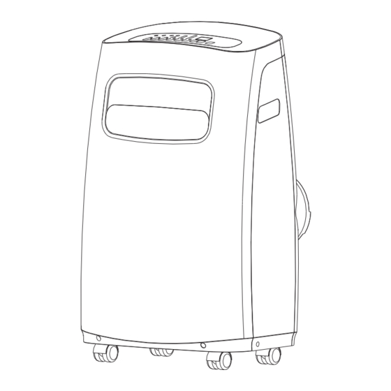
Preparation control panel upper air filter (behind the grille) handle (both sides) horizontal louver upper air intake blade drain outlet air outlet lower air filter lower air intake power plug socket drain outlet (only for pump heating mode) power cord outlet Caster power cord buckle bottom tray... -
Page 4: Safety Precautions
Safety Precautions Please read through these instructions before you start the -DO NOT install your air conditioner in a wet room such as installation process. Improper installation can cause damage a bathroom or laundry room. Too much exposure to water to the unit, your personal property, and also poses a personal can cause electrical components to short circuit. -
Page 5: Cautions
Cautions -This appliance is not intended for use by children or persons with reduced physical sensory or mental capabilities, unless they are supervised by a responsible adult or considered capable enough to operate the appliance safely. -Children should be supervised to ensure that they do not play with the appliance. -If the supply cord is damaged, it must be replaced by the manufacturer, its service agent or similarly qualified persons in order to avoid a hazard. -
Page 6: Installation
Installation Note About Fluorinated Gasses Choosing The Right Location -This air-conditioning unit is a hermetically sealed unit that contains fluorinated gasses. For specific information on the type of gas and the amount, please refer to the relevant label on the unit itself. -Installation, service, maintenance and repair of this unit must be performed by a certified technician. - Page 7 Installation Tools Needed Window Installation Kit -Medium Philips screwdriver; -Tape measure or ruler; -Knife or scissors; -Saw (optional, to shorten window adaptor for narrow windows) Step One: Preparing the Exhaust Hose assembly Accessories Press the exhaust hose into the window slider adaptor and unit adaptor, clamps automatically by elastic buckles of the adaptors.
- Page 8 Installation Note: Once the Exhaust Hose assembly and Adjustable Window Slider are prepared, choose from one of the following two installation methods. Type 1: Hung Window Installation Foam seal B (Adhesive type-shorter) Insert the window slider adaptor Window slider B Window slider A (if required) into the hole of the window slider.
- Page 9 Installation Note: While operating in cool mode, the exhaust hose will become Foam seal C (Non-adhesive type) warm to the touch (This is normal). Security Having the exhaust hose overextended can cause radiant heat into the Bracket room causing ineffective operation. 2 Screws Cut the non-adhesive foam If desired, install the security...
-
Page 10: Operation
Operation Swing button(optional) Timer button Mode button (Applicable to the models with Used to initiate the AUTO ON Selects the appropriate operating mode. Each auto swing feature only) start time and AUTO OFF stop time you press the button, a mode is selected Used to initiate the Auto swing time program, in conjunction with in a sequence that goes from AUTO, COOL,... -
Page 11: Led Display
Operation LED display - Shows the set temperature in °C or °F and the Auto-timer settings. read a p1 error on the display (it will stay like this until the unit is drained) if this happens, you should drain the water from the lower drain (located at the bottom of - While on DRY and FAN modes, it shows the room temperature. -
Page 12: Water Drainage
Operation SLEEP/ECO operation Water drainage -Press this button, the selected temperature will increase(cooling) or decrease(heating) by -During dehumidifying modes, remove the Remove the 1°C/1°F 30 minutes.The temperature will then increase (cooling) or decrease (heating) by upper drain plug upper drain plug from the back of the unit, another 1°C/1°F after an additional 30 minutes. -
Page 13: Maintenance
Maintenance Safety Precautions Clean the Unit Clean the unit using a damp, lint-free cloth and mild detergent. Dry the -Always unplug the unit before cleaning or servicing. unit with a dry, lint-free cloth. -DO NOT use flammable liquids or chemicals to clean the unit. -DO NOT wash the unit under running water. -
Page 14: Faults Diagnosis
Faults Diagnosis Please check the machine according to the following form before asking for maintenance: Problem Troubleshooting Possible Cause The Water Collection Tray is full. Turn off the unit, drain the water P1 Error Code from the Water Collection Tray Unit does not turn and restart the unit. -
Page 15: Design And Unit Temperature Range
Design and Compliance Notes Design Notice In order to ensure the optimal performance of our products, the design specifications of the unit and remote control are subject to change without prior notice. Unit Temperature Range Mode Temperature Range Cool 17-35°C (62-95°F) 13-35°C (55-95°F)
Need help?
Do you have a question about the P-12NPE and is the answer not in the manual?
Questions and answers
I need an exhaust hose, adapter b and window slider kit for a Model P-14NPE air conditioner
For the Magnavox P-14NPE air conditioner, the compatible exhaust hose, adapter B, and window slider kit options are:
- Exhaust Hose: 1 piece
- Window Slider Adaptor B: 1 piece
- Window Installation Kit includes:
- Window Slider A: 1 piece
- Window Slider B: 1 piece (Adapter B)
- Window Slider Adaptor: 1 piece
- Foam Seals A (adhesive): 2 pieces
- Foam Seals B (adhesive): 2 pieces
- Foam Seal C (non-adhesive): 1 piece
These components are used together to connect the unit's exhaust hose to a window for proper ventilation.
This answer is automatically generated
What diagnosis code is P3 on Magnovox P-12NPE
What does it mean when it says 12000 BTU..but says 6500 SACC ?? Portable ac
When i have unit in cool mode and it reaches temp the fan shuts off. How do i keep the fan going when it reaches temp?