Table of Contents
Advertisement
Quick Links
Clarion ( Malaysia) Sdn. Bhd.
Phase 3, Free Trade Zone One, 11900 Bayan Lepas, Penang, Malaysia
Tel: (60) 4-6439-106, Fax: (60) 4-6439-108
Clarion Co. Ltd.
Export Division : 50 Kamitoda, Toda-shi, Saitama 335-8511 Japan
SPECIFICATIONS
Radio section
Model: PE-2504B-B
Tuning system:
PLL synthesizer tuner
Receiving frequencies: FM 87.9 to 107.9MHz
(0.20 MHz
steps)
AM 530 to 1,710kHz
(10 kHz steps)
CD player section
System:
Compact disc audio system
Usable disc:
Compact disc
Frequency response:
10Hz to 20kHz (+1dB)
Signal to Noise ratio:
100dB (1kHz) IHF-A
Dynamic range:
95dB (1kHz)
Distortion:
0.01%
General
Max. Power Output:
50W x 4
Line Output:
1.7V (with CD 1kHz, 10k ohm)
Bass Control Action:
+13dB / -13dB (30Hz)
Trible Control Action:
+12dB / -12dB (10 kHz)
Power supply voltage: DC 14.4V (10.8 to 15.6V allowable
negative ground)
Current consumption: Less than 15A
Speaker impedance:
4ohm (4ohm to 8ohm allowable)
Dimensions (mm):
178 (W) x 50 (H) x 152 (D)mm
Weight:
1.0kg
*
Specification and design are subject to change without notice for
further improvement.
Published by Clarion (Malaysia)
289-6027-00 MAY 2003P
Printed In Malaysia
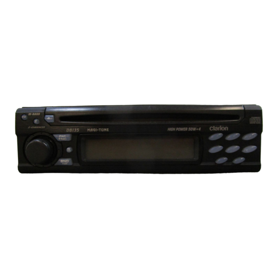
Service Manual
AM/FM Radio CD Combination
DB135
Model
(Model:PE-2504B-B For U.S.A)
NOTE
1.
We cannot supply PWB with component parts in
principle. When a circuit on PWB has failure, please
repair it by component parts base. Parts which are
not mentioned in service manual are not
supplied.
FEATURES
1.
Rotary Encoder Volume Control
2.
Z-Enhancer with 3 Mode Sound Selector
3.
FM Reception System
4.
Seek/Manual Up/Down Tuning
5.
8-Times Oversampling Digital Filter and Dual 1-Bit
D/A Converters
6.
Preset Station Scan (PS), Automatic Store (AS)
7.
2-Channel RCA Line Level Output
8.
AM 1 band, FM 3 bands each 6 channels total 24
channels, Preset Memory Function
9.
Repeat/Random Play/Intro Music Scan
10. 200W (50 W x 4) Maximum Power Output
COMPONENTS
PE-2504B-B
Main unit
Mounting bracket
300-7742-20
Escutcheon (Outer-Es) 370-9006-12
Extension Lead
854-6391-60
Part's bag
Removal key
331-2497-20
- 1 -
DB135
To engineers in charge of repair or
inspection of our products.
Before repair or inspection,make sure to follow the
instructions so that customers and Engineers in charge of
repair or inspection can avoid suffering any risk or injury.
1. Use specified parts.
The system uses parts with special safety features
against fire and voltage. Use only parts with equivalent
characteristics when replacing them.
The use of unspecified parts shall be regarded as re-
modeling for which we shall not be liable.The onus of
product liability (PL) shall not be our responsibility in
cases where an accident or failure is as a result of un-
specified parts being used.
2. Place the parts and wiring back in their original
positions after replacement or re-wiring.
For proper circuit construction, use of insulation tubes,
bonding, gaps to PWB, etc, is involved. The wiring con-
nection and routing to the PWB are specially planned
using clamps to keep away from heated and high volt-
age parts. Ensure that they are placed back in their origi-
nal positions after repair or inspection.
If extended damage is caused due to negligence during
repair, the legal responsibility shall be with the repairing
company.
3. Check for safety after repair.
Check that the screws, parts and wires are put back se-
curely in their original position after repair. Ensure for
safety reasons there is no possibility of secondary prob-
lems around the repaired spots.
If extended damage is caused due to negligence of re-
pair, the legal responsibility shall be with the repairing
company.
4. Caution in removal and making wiring connection to
the parts for the automobile.
Disconnect the battery terminal after turning the ignition
key off. If wrong wiring connections are made with the
battery connected, a short circuit and/or fire may occur.
If extensive damage is caused due to negligence of re-
pair, the legal responsibility shall be with the repairing
company.
5. Cautions regarding chips.
Do not reuse removed chips even when no abnormality
is observed in their appearance. Always replace them
with new ones. (The chip parts include resistors, capaci-
tors, diodes, transistors, etc). The negative pole of tan-
talum capacitors is highly susceptible to heat, so use
special care when replacing them and check the opera-
tion afterwards.
6. Cautions in handling flexible PWB.
Before working with a soldering iron, make sure that the
iron tip temperature is around 270°C. Take care not to ap-
1
ply the iron tip repeatedly (more than three times) to the
1
same patterns. Also take care not to apply the tip with force.
1
7. Turn the unit OFF during disassembly and parts replace-
1
ment. Recheck all work before you apply power to the
unit.
1
8. Cautions in checking that the optical pickup lights up.
2
The laser is focused on the disc reflection surface
through the lens of the optical pickup. When checking
that the laser optical diode lights up, keep your eyes
DB135
more than 30cms away from the lens. Prolonged
viewing of the laser within 30cms may damage your
eyesight.
9. Cautions in handling the optical pickup
The laser diode of the optical pickup can be damaged
by electrostatic charge caused by your clothes and body.
Make sure to avoid electrostatic charges on your clothes
or body, or discharge static electricity before handling
the optical pickup.
9-1.Laser diode
The laser diode terminals are shorted for transportation
in order to prevent electrostatic damage. After
replacement, open the shorted circuit. When removing
the pickup from the mechanism, short the terminals by
soldering them to prevent this damage.
9-2.Actuator
The actuator has a powerful magnetic circuit. If a
magnetic material is put close to it. Its characteristics
will change. Ensure that no foreign substances enter
through the ventilation slots in the cover.
9-3.Cleaning the lens
Dust on the optical lens affects performance. To clean
the lens, apply a small amount of isopropyl alcohol to
lens paper and wipe the lens gently.
CAUTIONS
Use of controls, adjustments, or performance of procedures
other those specified herein, may resault in hazardous
radiation exposure.
The compact disc player should not be adjustment or repaired
by anyone expext properly qualified service personnel.
(Model:PE-2504B-B)
Bottom View of
Main Unit
- 2 -
Advertisement
Table of Contents

Related Manuals for Clarion DB135


Summary of Contents for Clarion DB135
-
Page 1: Specifications
To engineers in charge of repair or more than 30cms away from the lens. Prolonged Clarion ( Malaysia) Sdn. Bhd. Published by Clarion (Malaysia) viewing of the laser within 30cms may damage your Phase 3, Free Trade Zone One, 11900 Bayan Lepas, Penang, Malaysia 289-6027-00 MAY 2003P inspection of our products. -
Page 2: Troubleshooting
-Check the compact unit CD ER6 This indicates that the CD’s TOC (table of contents) cannot be read, because the selected disc is upside-down. BLOCK DIAGRAM CD MECHANISM SECTION 929-0220-82 - 3 - - 4 - DB135 DB135... - Page 3 With disc, ‘H’ is input, without disc ‘L’ is ON, ‘LO’ is OFF input. CTRL1 Power Supply IC control terminal Z-MUTE Zero Mute for CD MECH (Active High) (Active High) - 5 - - 6 - DB135 DB135...
-
Page 4: Exploded View & Part List
331-3368-00 PWB HOLDER 017-0414-00 PILOT LAMP (8V 70mA) 347-6898-00 PAPER PART 347-6679-01 SHADE 039-2067-00 MAIN PWB (RIGHT ES-PWB) (WITHOUT COMPONENT) 001-7030-02 DIODE 335-6723-00 LED HOLDER 039-2067-00 MAIN PWB (LEFT ES-PWB) (WITHOUT COMPONENT) - 7 - - 8 - DB135 DB135... -
Page 5: Exploded View Parts List
621-0616-20 POWER GEAR A 621-0708-20 CLAMPER RING 621-0617-20 POWER GEAR B 621-0626-21 STOPPER LINK 621-0618-20 POWER GEAR C 621-0627-21 DISC STOPPER 621-0619-20 POWER GEAR D 750-3471-20 SENSOR SPRING 621-0620-20 THREAD GEAR A - 9 - - 10 - DB135 DB135... -
Page 6: Electrical Parts List
16V 2.2uF 113 102-2712-51 2SC2712GR 220 166-2211-00 16V 220pF 160 166-2201-00 50V 22pF 114 100-1298-00 2SA1298 O,Y 221 166-2211-00 16V 220pF 159 172-1041-11 50V 0.1uF 117 125-2004-02 RN1402 222 168-1022-05 16V 1000pF - 11 - DB135 - 12 - DB135... - Page 7 REF No. PART No. DESCRIPTION 001-7058-90 AN1105W-RR 074-1138-60 013-7413-50 LIMIT 001-7058-90 AN1105W-RR 013-7414-50 CHUCKING LED PWB-B section (B6): CD mechanism REF No. PART No. DESCRIPTION REF No. PART No. DESCRIPTION 060-4015-90 PS1192H 060-4015-90 PS1192H - 13 - DB135 - 14 - DB135...
- Page 8 - 15 - DB135...
-
Page 9: Circuit Diagram
CIRCUIT DIAGRAM 1/2 Main PWB (B1) Section 1/2 - 16 - DB135... -
Page 10: Printed Wiring Board
PRINTED WIRING BOARD Section (B1), (B2), (B3) - 17 - DB135... - Page 11 CIRCUIT DIAGRAM 2/2 Main PWB Section (B2) & (B3) Section 2/2 (B3) (B2) - 18- DB135...
- Page 12 CIRCUIT DIAGRAM PRINTED WIRING BOARD CD PWB (B4), (B5), (B6) CD Mechanism (B4), (B5), (B6) Section (B4) (B5) (B6) - 19 - DB135...
Need help?
Do you have a question about the DB135 and is the answer not in the manual?
Questions and answers