Advertisement
CONTROL PANEL FOR
SLIDING GATES
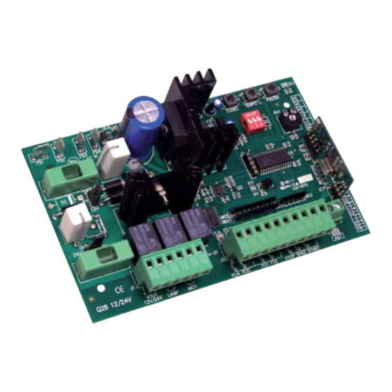
Q26
Control panel for sliding gate automation 12Vdc or 24Vdc
•
Streamlined programming procedure
•
Automatic setting of the obstacle detection level
•
Automatic setting of the deceleration time
•
Deceleration speed adjustment
•
Pause-time adjustment
•
Electric limit-switch in opening and closing
•
Outputs for safety photocells in opening and in closing
•
Outputs for START, PARTIAL OPENING and STOP push-buttons
•
Output for safety flashing light (Blinker)
•
Built-in battery-charger
TECHNICAL FEATURES
Control Panel Dimensions
Control Panel Weight
Transformer
Blinker Power Supply
Accessories Power Supply
Working time
Pause-time
Obstacle Detection Level
Box Dimensions
Protection Level
Instructions Manual
150 x 95 x 35 mm
0,20 Kg
80VA 230/12Vac for 12Vdc motor
80VA 230/20Vac for 24Vdc motor
12Vdc – 24Vdc, max 20W
12Vdc – 24Vdc, max 3W
ADJUSTABLE
ADJUSTABLE
AUTOMATIC
295 x 225 x 95 mm
IP55
12 dc
and
24V dc
Advertisement
Table of Contents

Subscribe to Our Youtube Channel
Related Manuals for Proteco Q26


Summary of Contents for Proteco Q26
- Page 1 CONTROL PANEL FOR 12 dc 24V dc SLIDING GATES Instructions Manual Control panel for sliding gate automation 12Vdc or 24Vdc • Streamlined programming procedure • Automatic setting of the obstacle detection level • Automatic setting of the deceleration time • Deceleration speed adjustment •...
- Page 2 Connect the control panel only to a power supply line equipped with safety grounding system. Wiring, settings and commissioning of this control board must be carried out by qualified and experienced personnel only. The installation has to comply to laws and regulations in force, with particular reference to EN 12445 provisions. Q26 _03_17...
-
Page 3: Wiring Diagram And Components
CLOSING PHOTOCELLS input (N.C. contact) OPENING PHOTOCELLS input (N.C. contact) COMMON inputs STOP push-button input (N.C. contact) PARTIAL OPENING push-button (N.O. contact) START push-button (N.O. contact) COMMON inputs = plugs for external AERIAL aerial cable (EARTH) aerial cable (SIGNAL) Q26 _03_17... - Page 4 24Vdc WIRING Diagram for motor Back-up Back-up battery battery Transformer 230V /20V ac 80VA 12V dc 1,2A 12V dc 1,2A 230Vac (MAIN) Fuse 5A AC IN 17 18 RF40 12-24V 12-24V ac /dc ac /dc Q26 _03_17...
- Page 5 12Vdc WIRING Diagram for motor Back-up battery Transformer 230V /12V ac 80VA 12V dc 1,2A 230Vac (MAIN) Fuse 5A AC IN 17 18 START Motor FLASHING LIGHT STOP 12Vdc max 20W RF40 12-24V 12-24V ac /dc ac /dc Q26 _03_17...
-
Page 6: Electric Wirings
The installation of an emergency stop push-button is highly recommended for the safety of people and objects. Note: Should you need to temporarily exclude the contact for the STOP push-button, i.e. during the installation procedure, you can make a jumper between plugs nr 13-16 on J2. Q26 _03_17... - Page 7 Transformer 230V /20V ac 80VA battery battery 12V dc 1,2A 12V dc 1,2A 230Vac (MAIN) Fuse 5A AC IN Electrical Mains wiring for motor 12Vdc (detail) Back-up Transformer 230V /12V ac 80VA battery 12V dc 1,2A 230Vac (MAIN) Fuse 5A AC IN Q26 _03_17...
-
Page 8: Selecting The Operating Mode
Now press on the radio transmitter the button you want to use to give a Start command. The code has been stored in the memory and DL1 goes off. The control panel can store up to 50 different radio codes. Q26 _03_17... -
Page 9: Pause-Time Setting
Proteco S.r.l. Via Neive, 77 - 12050 CASTAGNITO (CN) ITALY Tel. +39 0173 210111 - Fax +39 0173 210199 -...
Need help?
Do you have a question about the Q26 and is the answer not in the manual?
Questions and answers