Advertisement
Advertisement
Table of Contents

Related Manuals for Tempo Fitness TP-U2200


Summary of Contents for Tempo Fitness TP-U2200
- Page 1 TP-U2200 MAGNETIC BIKE www.tempofitness.com.au...
-
Page 2: Important Safety Information
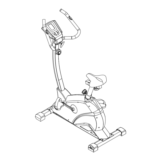
Important Safety Information Please keep this manual in a safe place for easy reference. 1. It is important to read this entire manual before assembling and using the equipment. Safe and effective use can only be achieved if the equipment is assembled, maintained and used properly. - Page 3 OVERVIEW DRAWING...
-
Page 4: Part List
PART LIST: DESCRIPTION DESCRIPTION BOLT M8*45 SCREW M3*10 WASHER ID8.5*OD16 ARC WASHER BOLT M8*16 30a,b TENSION KNOB AND CABLE 31a,b, SCREW M4*20 SENSOR WIRE 1set KNOB M8 HANDLE PULSE WIRE SLEEVE END CAP SCREW M5*10 U STYPE BUSHING KNOB M16 HANDLE COVER (FRONT) KNOB M10 HANDLE COVER (REAR) - Page 5 SEAT POST BUSHING WRENCH S6 PLASTIC BUSHING WRENCH S13-14-15 WASHER ID5*OD12...
- Page 6 ASSEMBLY:...
- Page 7 STEP 1: Assemble the front bottom tube and back bottom tube to the main frame, tighten the bottom tube with wrench (#L),bolt(#A) and washer(#B).
- Page 8 STEP 2: STEP2: According the picture tighten the pedal(#10L/R) with wrench(#M). RIGHT SIDE LEFT SIDE...
- Page 9 STEP3: 1. Assemble the cover(#37) to the handlebar assemble(#4), and then connect the tension knob ,cable (#30a/b) and sensor wire(#31a/b), according to the picture. 2. Pull up the cover, insert the handlebar assemble(#4) into the main frame(#1) , tighten them with bolt(#C) and washer(#B).
- Page 10 STEP 4: Attach the computer with #G screws.
- Page 11 STEP 5: Assemble the handle(#5)to the handle cover(front#35), and then tighten the handle cover(front#35) with sleeve(#F) and knob(#E), tighten the handle cover(rear#36) with screw(#D) and screw(#D).
- Page 12 STEP 6: The knob (#H) is available in the main frame. -10- After attaching the saddle (#9) with the saddle tube (#8),please secure tightly by tool S14. In order to prevent any injury, please check that all the parts are well fastened before using.
- Page 13 STEP 7: Sets the lowest magnetic force on the level 1 Sets the highest magnetic force on the level 8 desired distance between the handle bar and the saddle by adjusting the knob adjust seat’s height: A. Turn the knob about three turns in the counterclockwise direction.
- Page 14 COMPUTER...
Need help?
Do you have a question about the TP-U2200 and is the answer not in the manual?
Questions and answers