
Related Manuals for Munters FA6


Summary of Contents for Munters FA6
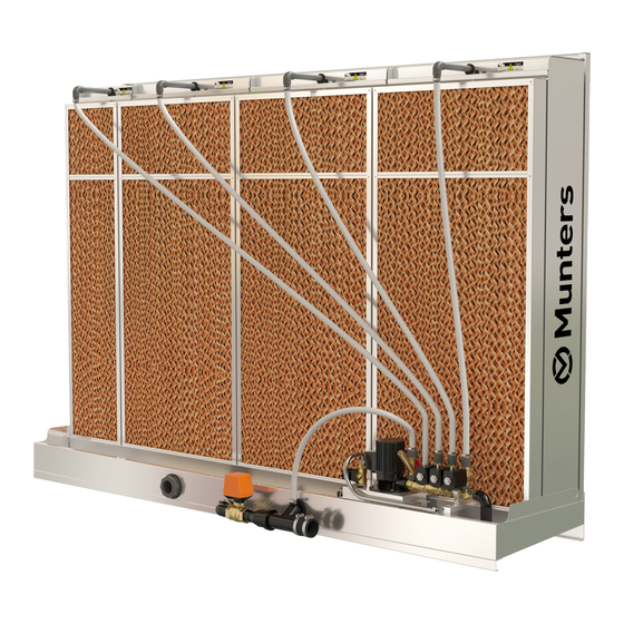
- Page 1 Evaporative Humidifier/Cooler FA6 for AHU’s – Installation instructions – Operation and Maintenance – Spare Parts HC/MMA/IGB-1712-06/10 pdf SOS ReklamStudio...
- Page 2 Disclaimer Munters reserves the right to make alterations to specifications, quantities, dimensions etc. for production or other reasons, subsequent to publication. The information contained herein has been prepared by qualified experts within Munters. While we believe the information is accurate and complete, we make no warranty or representation for any particular purposes.
-
Page 3: Table Of Contents
Dimensions, weights and pump sizes Installation Delivery conditions and storage Inspection Transport and lifting When delivered assembled When delivered as components Assembly instruction drain system FA6 Start-up Inspection before startup First start up/ Rinsing clean the humidifier Adjustment of bleed-off flow Service Periodic maintenance... -
Page 4: Fa6 Installation Planning
Simple to install Included in standard delivery for connection of water supply. The FA6 is easy to install and easy to configure into both exist- ing and new HVAC systems. Direct water system For installation you need to have access to electricity 1 Shutoff valve ½”... -
Page 5: Water Connection
µm is recommended to be installed. Direct-water system ∆ The total water consumption can be found in FA6 Technical manual, page 17. The cold-water supply is to be installed so that any conden- 2. Use the following formula to design the water trap: sation from the pipe falls into the reservoir. -
Page 6: Technical Specifications
9 KTF51 0.38/0.22 FA6-85 230/Y400 FA6-95 3-phase 10 KTF81 0.71/0.41 230/Y400 *) Sound level for FA6 unit is not above 70 dB. 3-phase 11 KTF82 50–60 0.95/0.55 230/Y400 Maximum continuous operating temperature Water Electrical – solenoid valve for step control GLASdek 200 °C... -
Page 7: Electrical Connections
Electrical connections Warning: High voltage is used in FA6 units! All electrical connections and wiring must be done according to national standards by qualified person- nel. To avoid damage on wires during normal oper- ation and service. Electrical connection for the pump motor... -
Page 8: Programming Off Bms/Control System
Programming off BMS/control system This is Munters recommendation of controlling the units in step control mode. Item BV drain SV supply** Pump step 1 SV step 2 SV step 3 SV step n Mode open Ready closed Step 1* closed... -
Page 9: Dimensions, Weights And Pump Sizes
Dimensions, weights and pump sizes FA6-65 FA6-85 FA6-95 C=630 mm, D=100 mm C=630 mm, D=200 mm C=730 mm, D=300 mm Dimensions Pump size Weight Pump size Weight Pump size Weight cassettes Width Width Size 300mm 600mm 060-060 060-090 060-120 1200... -
Page 10: Installation
Installation Delivery conditions and storage Transport and lifting Every humidifier is inspected before being delivered to ensure The humidifier must always be handled carefully. Provided that good quality. If a humidifier needs to be stored before installa- the packing material has not been removed, the humidifier can tion, it must be covered and protected from physical damage as be lifted by a crane or fork-lift truck. -
Page 11: When Delivered As Components
Don’t tighten the hose clip so tight that the dis- charge pipe is deformed. A water trap is recommended. 8. Connect FA6 unit to BMS/Control system. Please note that all electrical wiring must be done according to national 5. -
Page 12: Assembly Instruction Drain System Fa6
Assembly instruction drain system FA6 Drain system is not mounted when unit is delivered. 4. Mount rubber seal for drain system. 1. Mount rubber sealing on plug insert plug from inside of tray Mount plug on left or right side depending on what service side is required. -
Page 13: Start-Up
Check that the connections are tight. Note that no service work may be started before the safety switch of the FA6 unit is in its ”off ” position. The level of the water in circulating-water hu- midifiers is very important. If the level is consis-... -
Page 14: Cleaning The Reservoir And Pump Filter
Option 1. Connect the distribution-header pipe to a pressurized cold-wa- 3. Remove the distribution header by unhooking it from the ter system. Flush clean. In most cases, this will be sufficient. cross beam on the front of the humidifier. Option 2. Loosen the end plugs. -
Page 15: Disassembly Of Cassettes And Droplet Separators
Disassembly of cassettes and droplet separators Restart after service 1. Remove the distribution header as shown in 1. Shut the bottom valve. 2. Switch on the pump’s safety switch. 3. Check that the snap catches on the top of the distribution headers are in place. -
Page 16: Fault-Finding
Fault-finding table If the humidifier fails to function properly, the check list below may help in finding the fault before contacting the Munters service organization. The plant’s maintenance personnel will be able to easily identify simple faults with the help of the check list. -
Page 17: Spare Parts
When ordering parts always try to provide the following details: • FA6 type/part no. (refer to identification plate on unit) • Date of manufacture (refer to identification plate) • Serial number (refer to identification plate on unit and also illustration to the right.) -
Page 18: Spare-Parts List
J. Motorized drain valve ....180CU1079 New FA6 K. Water trap incl 40-50 adapter ....180CU1060... -
Page 19: Item Number For Humidifier Modules
The modules are available in two widhts. 295 mm 595 mm Item number for droplet separator The number of droplet separators for each FA6 size is the same as the number of cassettes. Separator Width Width height code... - Page 20 China Munters Air Treatment Equipment (Beijing) Co. Ltd., Phone +86 10 80 481 121, Denmark Munters Turbovent, Phone +45 9862 3311, Finland Munters Oy, Phone +358 20 748 4214, France Munters France S.A., Phone +33 1 34 11 57 50, Germany Munters Euroform GmbH, Phone +49 241 89 00 0, India Munters India, Phone +91 20 3052 2520, Indonesia Munters, Phone +62 818 739 235, Italy Munters Italy S.p.A., Chiusavecchia Phone +39 0183-52 11, Munters Italy S.p.A., Mondovì...
Need help?
Do you have a question about the FA6 and is the answer not in the manual?
Questions and answers