Table of Contents
Advertisement
MICRO COMPONENT SYSTEM RDX-E600
The RDX-E600 is composed of the RX-E600, NX-E400 and the DVD-E600.
This service manual is for the DVD-E600.
For the RX-E600 and the NX-E400 service manual, please refer to the following
publication number:
RDX-E600はRX-E600、NX-E400及びDVD-E600で構成されています。
このサービスマニュアルはDVD-E600用です。
RX-E600及びNX-E400のサービスマニュアルは下記を参照してください。
This manual has been provided for the use of authorized YAMAHA Retailers and their service personnel.
It has been assumed that basic service procedures inherent to the industry, and more specifically YAMAHA Products, are already
known and understood by the users, and have therefore not been restated.
WARNING:
Failure to follow appropriate service and safety procedures when servicing this product may result in personal
injury, destruction of expensive components, and failure of the product to perform as specified. For these reasons,
we advise all YAMAHA product owners that any service required should be performed by an authorized YAMAHA
Retailer or the appointed service representative.
IMPORTANT:
The presentation or sale of this manual to any individual or firm does not constitute authorization, certification or
recognition of any applicable technical capabilities, or establish a principle-agent relationship of any form.
The data provided is believed to be accurate and applicable to the unit(s) indicated on the cover. The research, engineering, and service
departments of YAMAHA are continually striving to improve YAMAHA products. Modifications are, therefore, inevitable and
specifications are subject to change without notice or obligation to retrofit. Should any discrepancy appear to exist, please contact the
distributor's Service Division.
WARNING:
Static discharges can destroy expensive components. Discharge any static electricity your body may have accumu-
lated by grounding yourself to the ground buss in the unit (heavy gauge black wires connect to this buss).
IMPORTANT:
Turn the unit OFF during disassembly and part replacement. Recheck all work before you apply power to the unit.
I
CONTENTS
TO SERVICE PERSONNEL . . . . . . . . . . . . . . . . . . 2~5
PREVENTION OF ELECTRO STATIC DISCHARGE . . . . . . 5
LOCALE MANAGEMENT INFORMATION . . . . . . . . 5
FRONT PANEL . . . . . . . . . . . . . . . . . . . . . . . . . . . . . . 6
REMOTE CONTROL PANEL . . . . . . . . . . . . . . . . . . . 6
REAR PANELS . . . . . . . . . . . . . . . . . . . . . . . . . . . . 6~7
INTERNAL VIEW . . . . . . . . . . . . . . . . . . . . . . . . . . . . . 7
. . . . . . . . . . . . . . . . . . . . . . . . . . . . . . . . . . 8~9
1 0 0 9 2 4
RX-E600/NX-E400
RX-E600/NX-E400
IMPORTANT NOTICE
. . . . . . . . . . . . . . . . . . . . 7
DVD-E600
SERVICE MANUAL
SERVICE MANUAL
100923
100923
IC DATA . . . . . . . . . . . . . . . . . . . . . . . . . . . . . . . . 18~19
DISPLAY DATA . . . . . . . . . . . . . . . . . . . . . . . . . . . . . 20
BLOCK DIAGRAM . . . . . . . . . . . . . . . . . . . . . . . . . . . 21
PRINTED CIRCUIT BOARD . . . . . . . . . . . . . . . . 22~26
SCHEMATIC DIAGRAM . . . . . . . . . . . . . . . . . . . 27~35
PIN CONNECTION DIAGRAM . . . . . . . . . . . . . . . . . 36
PARTS LIST . . . . . . . . . . . . . . . . . . . . . . . . . . . . . 36~39
. . . . . . . . . . . . . . . . . 10~17
'04.10
Advertisement
Table of Contents

Related Manuals for Yamaha DVD-E600


Summary of Contents for Yamaha DVD-E600
-
Page 1: Table Of Contents
This manual has been provided for the use of authorized YAMAHA Retailers and their service personnel. It has been assumed that basic service procedures inherent to the industry, and more specifically YAMAHA Products, are already known and understood by the users, and have therefore not been restated. -
Page 2: To Service Personnel
DVD-E600 TO SERVICE PERSONNEL AC LEAKAGE 1. Critical Components Information TESTER OR WALL EQUIPMENT Components having special characteristics are marked Z EQUIVALENT OUTLET UNDER TEST and must be replaced with parts having specifications equal to those originally installed. 2. Leakage Current Measurement (For 120V Models Only) - Page 3 DVD-E600 WARNING: Laser Safety 警告:レーザーの安全対策 This product contains a laser beam component. This 本機はレーザー光線を放射する部品を搭載しています。 こ component may emit invisible, as well as visible radiation, の部品が放射するレーザー光線は目に損傷を起こします。 which may cause eye damage. To protect your eyes このレーザー光線から目及び肌を保護するために、 本機の and skin from laser radiation, the following precautions 修理作業中は下記の注意を厳守してください。...
- Page 4 DVD-E600 WARNING CAUTION The unit is not disconnected from the AC power source as long as it is connected to the wall outlet,even if this unit Use of controls or adjustments or performance of itself is turned off.This state is called the standby mode.In...
-
Page 5: Prevention Of Electro Static Discharge
DVD-E600 Warning for power supply The primary side of the power supply carries live mains voltage when the player is connected to the mains even when the player is switched off ! This primary area is not shielded so it is possible to touch copper tracks and/or components when servicing the player. -
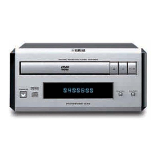
Page 6: Front Panel
DVD-E600 FRONT PANEL REMOTE CONTROL PANEL REAR PANELS U, C models R model K model A model B, G, E models... -
Page 7: Specifications / 参考仕様
DVD-E600 L model J model DIMENSIONS / 寸法図 (DVD-E600) I SPECIFICATIONS / 参考仕様 PLAYBACK SYSTEM / 対応ディスク DVD Video Digital Output 1 coaxial, 1 optical Video CD & SVCD IEC958 for CDDA / LPCM/ MPEG1 IEC1937 for MPEG 2, Dolby... -
Page 8: Disassembly Procedures / 分解手順
DVD-E600 I DISASSEMBLY PROCEDURES / 分解手順 (Remove parts in the order as numbered.) (番号順に部品を取り外してください。) OPERATION (2) P.C.B. Disconnect the power cable from the AC outlet. AC電源コンセントから、電源コードを抜いてください。 1. Removal of Top Cover 1. トップカバーの外し方 VIDEO P.C.B. a. Remove 4 screws (1), 4 screws (2) in Fig. 1. - Page 9 DVD-E600 7. POWER SUPPLY UNITの外し方 7. Removal of POWER SUPPLY UNIT a. Remove 2 screws (A) in Fig. 5. a. ⑪のネジ2本を外します。 (Fig. 5) b. Loosen 2 spacers in Fig. 5. b. スペーサー2個をゆるめます。 (Fig. 5) c. コネクター 0100を外します。 (Fig. 5) c. Remove a connector (0100) in Fig. 5.
-
Page 10: Maintenance Flow Chart
DVD-E600 I MAINTENANCE FLOW CHART Start Power on 1. Check Cable Voltages 2. Replace Power Supply Unit if Mono Board is not shorted, at all pins of connector (Ref 1601) otherwise find out first where the short is. are normal ? -
Page 11: メンテナンスフローチャート
DVD-E600 メンテナンスフローチャート 開始 電源ON 1. ケーブルをチェックする コネクター(Ref 1601)の 2. Mono P.C.B.がショートしていなければ電源ユニットを交換する 全部のピンの電圧が ショートしていたら、最初にショートがどこで起きたか調べる 正常か DV33と LD1117 (Ref 7601) と1N4002 (Ref 6604) と周辺回路をチェックする V25は正常か TV画面に 74HC04 (Ref 7605) メインクロックは LOGOが表示されるか の周辺回路チェックする 正常か NPC302 (Ref 7650) リセット信号は の周辺回路チェックする 正常か FLASH FLASH( Ref 7611) の周辺回路を... - Page 12 DVD-E600 Are Signals TROUT Does the tray Check the position-switch (Pin 48 of MT1336E) and automatically close when on the DVD mechanism TRIN (Pin 47 of MT1336E) it is open? correct ? Are Signals Check the circuit between TRCLOSE & TROPEN...
- Page 13 DVD-E600 信号TROUT DVDメカ上の トレーが (MT1336Eの48ピン)とTRIN ポジション・スイッチを 開いている時、自動的に (MT1336Eの47ピン)は チェックする 閉まるか 正しいか 信号 MT1336EとBA5954間の回路 TRCLOSEとTROPENは をチェックする 正しいか 信号 LOAD+とLOAD-は BA5954と周辺をチェックする 正しいか DVDメカを接続する回路を チェックする スレッドが 信号 STBYに関連する回路を 外周側にある時、自動的に内周側に STBY(BA5954の28ピン)は チェックする 移動するか "H"レベルか 信号 FMSOに関連する回路を FMSO(BA5954の23ピン)は チェックする 1.4V以上か 信号SL+ (BA5954の17ピン)と BA5954をチェックする SL-(BA5954の18ピン)は 正しいか...
- Page 14 DVD-E600 Check the peripheral Signal circuit of MT1336E When read disc, LDO1 and LDO2 are Check the peripheral is Laser on OK ? normal ? circuit of two transistor (Ref 7620 & 7621) Voltage of Check the peripheral TP22 &TP24...
- Page 15 DVD-E600 MT1336Eの周辺回路を 信号 チェックする ディスクの読み取り時に LDO1とLDO2は 2個のトランジスター レーザーONはOKか 正常か (Ref 7620と7621)の 周辺回路をチェックする 2個のトランジスター TP22と TP24の電圧は (Ref 7620と7621)の OKか 周辺回路をチェックする DVDメカを接続している回路を レーザーOFF ディスクが搭載されているか チェックする 光ピックアップが損傷している かもしれない MT1336Eの 光ピックアップとMT1336E間 ピンA, B, C, D, E, Fのどれ フォーカスONはOKか の回路をチェックする かの信号がONになって いるか 信号 MT1336Eの周辺回路を FEO(MT1336Eの18ピン)は...
- Page 16 DVD-E600 Is Signal TEO Check MT1336E and its Is Track on OK ? (pin 21 of MT1336E) peripheral circuit. normal ? Check the connection Is Signal TRSO between MT1379BE (pin 13) (pin13 of MT1379BE) and MT1336E (pin 26) normal ?
- Page 17 DVD-E600 信号TEO MT1336Eとその周辺回路を トラックONはOKか (MT1336Eの21ピン)は チェックする 正常か MT1379BEの13ピンと 信号TRSO BA5954の26ピン間の接続を (MT1379BEの13ピン)は チェックする 正常か 信号T+ BA5954とその周辺回路を (TP3)とT-(TP14) チェックする は正常か 光ピックアップとBA5954の間 の接続をチェックする ディスクはスタンバイ状態か RF信号をチェックする AKM4382A MT1379BEとAKM4382A間の接続を オーディオ信号は正常か が正しいデータを チェックする 受信するか AKM4382Aとその周辺回路を 出力信号は正しいか チェックする フィルター、アンプ、 ミュートなどの回路を チェックする GP1UM271XK, リモコン受光ユニット、 MT1379BEとuPD16312GB間の uPD16312GBとMT1379BEとの FLディスプレー、キー 接続とその周辺回路をチェックする...
-
Page 18: Ic Data
DVD-E600 IC DATA IC1 : µPD16312GB-3B4 (OPERATION P.C.B.) 8bit CPU Grid Grid /Grid /Grid /Grid /Grid /Grid Command decoder Dimming circuit 16-bit Seg- Display memory output ment Serial I/F 16 bits x 11 words latch driver /Grid Timing generator key scan... - Page 19 DVD-E600 IC1 : µPD16312GB-3B4 (OPERATION P.C.B.) 8bit CPU Name Symbol Description Switch input These pins constitute a 4-bit general-purpose input port. Data output DOUT Output serial data at the falling edge of the shift clock, starting from low order bit. This is N-ch open-drain output pin.
-
Page 20: Display Data
DVD-E600 DISPLAY DATA G V1 : 7-BT-299GNK (WD602800) PATTERN AREA G PIN CONNECTION PIN NO. CONNECTION F2 NOTE : 1) F1, F2 ..Filament 2) NP ..No pin 3) 1G ~ 7G ..Grid G GRIG ASSIGNMENT G ANODE CONNECTION... -
Page 21: Block Diagram
DVD-E600 I BLOCK DIAGRAM 7611 7609 MONO BOARD OUTPUT 1603 S-VIDEO SD5.4 8 Mbit 64 Mbit 1606 COMPONENT VIDEO FLASH SDRAM 1605 VIDEO COAXIAL 1614 AUDIO OUT 7607 OPTICAL 7606 7615 7602 7603 7637-7642 MT1379BE +D5V SERVO and MPEG MOTOR... - Page 22 DVD-E600 The first digit of a component indicates the component type. I PRINTED CIRCUIT BOARD 1xxx : Connector 3xxx : Resistor 5xxx : Coil 7xxx : IC, Transistor, FET SD5.4 MONO (SIDE A) FOR INFORMATION ONLY (NO SERVICE PARTS WILL BE AVAILABLE)
- Page 23 DVD-E600 The first digit of a component indicates the component type. I PRINTED CIRCUIT BOARD 1xxx : Connector 3xxx : Resistor 5xxx : Coil 7xxx : IC, Transistor, FET SD5.4 MONO (SIDE B) FOR INFORMATION ONLY (NO SERVICE PARTS WILL BE AVAILABLE)
- Page 24 DVD-E600 The first digit of a component indicates the component type. I PRINTED CIRCUIT BOARD 1xxx : Connector 3xxx : Resistor 5xxx : Coil 7xxx : IC, Transistor, FET VIDEO FOR INFORMATION ONLY (NO SERVICE PARTS WILL BE AVAILABLE) 2xxx : Capacitor...
-
Page 25: Printed Circuit Board
DVD-E600 I PRINTED CIRCUIT BOARD OPERATION (1) P.C.B. (Side A) POWER SUPPLY UNIT STANDBY/ON PREV NEXT STBY_DECT SWIR +5STBY OPEN/CLOSE PLAY/PAUSE STOP MONO BORARD (1608) OPERATION (1) P.C.B. (Side B) Lead Free Solder Used • Semiconductor Location Ref. No. Location... - Page 26 DVD-E600 I PRINTED CIRCUIT BOARD OPERATION (2) P.C.B. (Side A) OPERATION (2) P.C.B. (Side B) Lead Free Solder Used VIDEO BOARD (1100) OPERATION (1) (CB3) DVD SYSTEM CONNECTOR A_MUTE AUDIO_R -12V AUDIO_L +12V +5VL 0/2/5 D-CRTL2 D-CRL1 V-SWITCH S-CTR2 S-CTR1...
- Page 27 DVD-E600 The first digit of a component indicates the component type. I SCHEMATIC DIAGRAM 1xxx : Connector 3xxx : Resistor 5xxx : Coil 7xxx : IC, Transistor, FET FOR INFORMATION ONLY (NO SERVICE PARTS WILL BE AVAILABLE) 2xxx : Capacitor...
- Page 28 DVD-E600 The first digit of a component indicates the component type. I SCHEMATIC DIAGRAM 1xxx : Connector 3xxx : Resistor 5xxx : Coil 7xxx : IC, Transistor, FET FOR INFORMATION ONLY (NO SERVICE PARTS WILL BE AVAILABLE) 2xxx : Capacitor...
- Page 29 DVD-E600 The first digit of a component indicates the component type. I SCHEMATIC DIAGRAM 1xxx : Connector 3xxx : Resistor 5xxx : Coil 7xxx : IC, Transistor, FET FOR INFORMATION ONLY (NO SERVICE PARTS WILL BE AVAILABLE) 2xxx : Capacitor...
- Page 30 DVD-E600 The first digit of a component indicates the component type. I SCHEMATIC DIAGRAM 1xxx : Connector 3xxx : Resistor 5xxx : Coil 7xxx : IC, Transistor, FET FOR INFORMATION ONLY (NO SERVICE PARTS WILL BE AVAILABLE) 2xxx : Capacitor...
- Page 31 DVD-E600 The first digit of a component indicates the component type. I SCHEMATIC DIAGRAM 1xxx : Connector 3xxx : Resistor 5xxx : Coil 7xxx : IC, Transistor, FET FOR INFORMATION ONLY (NO SERVICE PARTS WILL BE AVAILABLE) 2xxx : Capacitor...
- Page 32 DVD-E600 The first digit of a component indicates the component type. I SCHEMATIC DIAGRAM 1xxx : Connector 3xxx : Resistor 5xxx : Coil 7xxx : IC, Transistor, FET FOR INFORMATION ONLY (NO SERVICE PARTS WILL BE AVAILABLE) 2xxx : Capacitor...
- Page 33 DVD-E600 The first digit of a component indicates the component type. I SCHEMATIC DIAGRAM 1xxx : Connector 3xxx : Resistor 5xxx : Coil 7xxx : IC, Transistor, FET FOR INFORMATION ONLY (NO SERVICE PARTS WILL BE AVAILABLE) 2xxx : Capacitor...
-
Page 34: Schematic Diagram
DVD-E600 I SCHEMATIC DIAGRAM (OPERATION 1/2) IC2 : HD74HC126FP Quadruple Bus Buffer Gates (with 3-state outputs) STANDBY/ON FTD DISPLAY 1P 22 µPROCESSOR TACT SWITCH OPE (1) Page 35 D5 To CB5 of OPERATION (2) # All voltages are measured with a 10MΩ/V DC electronic volt meter. - Page 35 DVD-E600 I SCHEMATIC DIAGRAM (OPERATION 2/2) To DVD MECHANISM UNIT # All voltages are measured with a 10MΩ/V DC electronic volt meter. # Components having special characteristics are marked s and must be replaced with parts having specifications equal to those originally installed.
-
Page 36: Pin Connection Diagram
DVD-E600 PARTS LIST PIN CONNECTION DIAGRAM I ELECTRICAL PARTS uPD16312 HD74HC123FPEL I WARNING Components having special characteristics are marked s and must be replaced with parts having specifications equal to those originally installed. ●s印のある部分は、 安全確保部品を示 しています。 部品の交換が必要な場合、 パーツ リ ス トに記載されている部品を使用 して く ださい。... - Page 37 DVD-E600 P.C.B. OPERATION P.C.B. OPERATION & Chip Parts Ref. Ref. PART NO. Description Remarks Markets 部品名 Rank PART NO. Description Remarks Markets 部品名 Rank WD854900 P.C.B. OPERATION JBGE PCB オペレーション WD890100 SHEET.FL シート/FLオレンジ WD921200 P.C.B. OPERATION UCRKAL PCB オペレーション WD890000 SHEET.FL シート/FLアオ...
-
Page 38: Exploded View
DVD-E600 I EXPLODED VIEW 1-1 (3) 1-1 (2) U, C, R, K, A, L models B, G, E, J models B, G, E models J model 1-103 1-102 1-110 1-101 1-110 1-104 1-103 % : Note on the OPERATION P.C.B. (1-1) % : OPERATION P.C.B. - Page 39 DVD-E600 WARNING I MECHANICAL PARTS Components having special characteristics are marked Z and must be 印のある部分は、安全確保部品を示しています。部品の交換が必要な場合、 replaced with parts having specifications equal to those originally installed. パーツリストに記載されている部品を使用してください。 Ref. Ref. PART NO. Description Remarks Markets 部品名 Rank PART NO. Description Remarks Markets 部品名...
- Page 40 DVD-E600 MEMO DVD-E600...
Need help?
Do you have a question about the DVD-E600 and is the answer not in the manual?
Questions and answers