AudioCodes mediant 500l msbr Installation Manual
Multi-service business routers (msbr)
Hide thumbs
Also See for mediant 500l msbr:
- User manual (1260 pages) ,
- Hardware installation manual (54 pages) ,
- Connecting manual (42 pages)
Table of Contents
Advertisement
Quick Links
Download this manual
See also:
User Manual
Advertisement
Table of Contents

Related Manuals for AudioCodes mediant 500l msbr


Summary of Contents for AudioCodes mediant 500l msbr
- Page 1 Hardware Installation Manual AudioCodes Multi-Service Business Routers (MSBR) Mediant™ 500L MSBR...
-
Page 3: Table Of Contents
Connecting to the Power Supply ................39 5.7.1 3-Amp Power Supply Cabling ................. 39 5.7.2 5-Amp Power Supply Cabling ................. 42 5.7.3 Powering On or Off the Device ................42 A Approved Laser SFPs ..................43 MSBR Series Mediant 500L MSBR... - Page 4 Mediant 500L MSBR List of Figures Figure 3-1: Front Panel .......................... 15 Figure 4-1: Orienting Wi-Fi Antenna ...................... 21 Figure 5-1: Cabling the WAN Copper GbE Port ..................24 Figure 5-2: Removing Protective Dust Plug ..................25 Figure 5-3: Cabling the Fiber-Optic WAN GbE Port ................26 Figure 5-4: Cabling the xDSL WAN Port ....................
- Page 5 Table 5-3: RJ-45 Connector Pinouts for FE ..................29 Table 5-4: RJ-45 to DB-9 Serial Cable Connector Pinouts ..............37 Table 5-5: Power Specifications ......................39 Table 5-6: Power Adapter with Interchangeable Plugs ................. 40 Table A-1: Approved SFP Modules ....................... 43 MSBR Series Mediant 500L MSBR...
- Page 6 Mediant 500L MSBR This page is intentionally left blank. Hardware Installation Manual Document #: LTRT-10444...
-
Page 7: Weee Eu Directive
Customer Support Customer technical support and services are provided by AudioCodes or by an authorized AudioCodes Service Partner. For more information on how to buy technical support for AudioCodes products and for contact information, please visit our Web site at www.audiocodes.com/support. -
Page 8: Related Documentation
Mediant 500L MSBR Related Documentation Document Name SIP Release Notes Mediant 500L MSBR User's Manual CLI Reference Guide General Notes and Warnings, and Safety Information Note: Open source software may have been added and/or amended for this product. For further information, please visit our website at http://audiocodes.com/support... -
Page 9: Document Revision Record
10444 DSL connector pinouts updated Documentation Feedback AudioCodes continually strives to produce high quality documentation. If you have any comments (suggestions or errors) regarding this document, please fill out the Documentation Feedback form on our Web site at http://www.audiocodes.com/downloads. Your valuable feedback is highly appreciated. - Page 10 Mediant 500L MSBR This page is intentionally left blank. Hardware Installation Manual Document #: LTRT-10444...
-
Page 11: Introduction
Notes: • Hardware configurations may change without notice. Currently available hardware configurations are listed in AudioCodes Price Book. For further enquiries, please contact your AudioCodes sales representative. • For information on configuring the device, refer to the device's User’s Manual. - Page 12 Mediant 500L MSBR This page is intentionally left blank. Hardware Installation Manual Document #: LTRT-10444...
-
Page 13: Unpacking The Device
• Two Wi-Fi antennas (depending on ordered model) • Serial cable adapter • AC/DC power adapter Check, retain and process any documents. If there are any damaged or missing items, notify your AudioCodes sales representative. MSBR Series Mediant 500L MSBR... - Page 14 Mediant 500L MSBR This page is intentionally left blank. Hardware Installation Manual Document #: LTRT-10444...
-
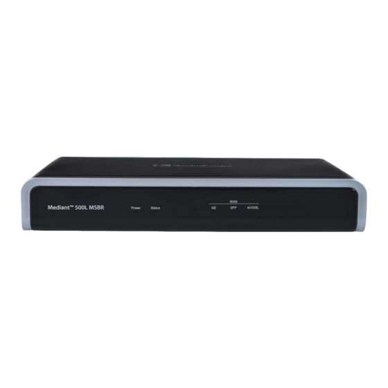
Page 15: Physical Description
Figure 3-1: Front Panel Note: The figure above is used only as an example. The available LEDs depend on the ordered hardware configuration. MSBR Series Mediant 500L MSBR... -
Page 16: Led Descriptions
Mediant 500L MSBR Table 3-2: Front Panel Description Item # LED Label Description Power Indicates the status of the power supply to the device. For more information, see Section 3.2.1 on page 16. Status Indicates the operating status of the device. For more information, see Section 3.2.1.2... -
Page 17: Wi-Fi Led
The WAN SFP LED indicates the status of the optical fiber WAN link, as described in the table below. Table 3-7: WAN SFP LED Description Description Color State Green WAN fiber link established. Flashing Data is being received or transmitted. No WAN fiber link or power not received by the device. MSBR Series Mediant 500L MSBR... -
Page 18: Table 3-8: Wan A/Vdsl Led Description
Mediant 500L MSBR 3.2.1.4.3 A/VDSL WAN LED The WAN A/VDSL LED indicates the status of the A/VDSL WAN link, as described in the table below. Table 3-8: WAN A/VDSL LED Description LED State Description Color Green DSL link connected (trained) successfully with peer ("showtime"). -
Page 19: Rear Panel Description
WAN interface ports, which can be any of the following (depending on ordered configuration): GE: Copper GE GE SFP: SFP module - dual-mode supporting 1.25 Gbps V/ADSLoPOTS: ADSL/2+ and VDSL2 Note: For available WAN configurations, contact your AudioCodes MSBR Series Mediant 500L MSBR... -
Page 20: Lan Interface Leds
Mediant 500L MSBR Item # Label Description sales representative. FE LAN Up to four Fast Ethernet (10/100Base-T) ports (RJ-45) for connecting to LAN network such as IP phones, computers, and switches. These ports support half- and full-duplex modes, auto- negotiation, and straight or crossover cable detection. -
Page 21: Orienting The Wi-Fi Antennas
This section is applicable only for models ordered with the Wi-Fi functionality. Switching Wi-Fi On and Off The wireless LAN interface can be turned on or off by pressing the Wi-Fi pinhole button located on the rear panel (see Section on page 19). MSBR Series Mediant 500L MSBR... - Page 22 Mediant 500L MSBR This page is intentionally left blank. Hardware Installation Manual Document #: LTRT-10444...
-
Page 23: Cabling The Device
WAN interface is Copper GbE and it fails, the device switches over to the fiber-optic WAN interface. If this WAN interface also fails, the device switches over to the 3G WAN interface, and so on. For configuring WAN redundancy, refer to the CLI Reference Guide. MSBR Series Mediant 500L MSBR... -
Page 24: Copper Gigabit Ethernet
Mediant 500L MSBR 5.1.1 Copper Gigabit Ethernet The device provides a copper Gigabit Ethernet (GbE) port interface for connecting to the WAN. Cable specification: Cable: straight-through Cat 5 cable Connector: RJ-45 Connector Pinouts: Table 5-1: RJ-45 Connector Pinouts for Copper GbE WAN... -
Page 25: Fiber-Optic Gigabit Ethernet
Notes: • The SFP module and fiber-optic cable are not supplied. It is recommended that you purchase the SFP modules from AudioCodes. For a list of orderable SFP modules, see Appendix on page 43, or contact your AudioCodes sales representative. -
Page 26: Adsl2+ And Vdsl2
ITU G.991.2 Annex E for Ethernet, also known as EFM or 2Base-TL, as defined in IEEE 802.3ah • 802.1q VLANs over EFM • PPPoE Note: The xDSL interface is a customer-ordered item which is supported only on specific hardware configurations. For more information, contact your AudioCodes sales representative. Hardware Installation Manual Document #: LTRT-10444... -
Page 27: Figure 5-4: Cabling The Xdsl Wan Port
Connect an RJ-11 cable connector to the device’s xDSL WAN port (labeled V/ADSLoPOTS). Figure 5-4: Cabling the xDSL WAN Port Connect the other end of the cable to the access point. Note: The xDSL filter/splitter is not supplied and should be provided by your service provider. MSBR Series Mediant 500L MSBR... -
Page 28: 3.5G Cellular Usb Modem
(PPP) over cellular. Note: To verify whether your third-party, 3G cellular modem is supported by the device, please provide the modem's model details to your AudioCodes sales representative. To connect the 3G cellular WAN modem: ... -
Page 29: Connecting Lan Interfaces
Connect one end of a straight-through RJ-45 Cat 5e or Cat 6 cable to the LAN port, located on the rear panel and labeled FE LAN. Figure 5-6: Cabling LAN Ports Connect the other end of the cable to a network device or entity. MSBR Series Mediant 500L MSBR... -
Page 30: Isdn Bri Interfaces
To protect against electrical shock and fire, use a 26 AWG min. wire to connect the BRI ports to the PSTN. Note: BRI interface is a customer-ordered item which is supported only on specific hardware configurations. For more information, contact your AudioCodes sales representative. Cable specification: ... -
Page 31: Figure 5-8: Cabling Bri Ports
To connect a BRI line: Connect the RJ-45 cable to the device's BRI port, located on the rear panel and labeled BRI. Figure 5-8: Cabling BRI Ports Connect the other end of the cable to your ISDN equipment. MSBR Series Mediant 500L MSBR... -
Page 32: Connecting Pstn Fallback For Bri Lines
The BRI PSTN Fallback feature is a customer-ordered item, which is supported only on specific hardware configurations providing BRI interfaces. For more information, contact your AudioCodes sales representative. • The scenarios upon which the BRI PSTN Fallback is activated (i.e., power outage and/or IP network loss) are configured by the TrunkLifeLineType parameter. -
Page 33: Analog Interfaces
FXS ports are considered TNV-2. Notes: • FXS interface is a customer-ordered item which is supported only on specific hardware configurations. For more information, contact your AudioCodes sales representative. • The FXS/FXO interfaces support loop-start signaling (indoor only). Cable specification: ... -
Page 34: Figure 5-11: Cabling Fxs Interfaces
Mediant 500L MSBR To connect an FXS interface: Connect one end of an RJ-11 cable to an FXS port, located on the rear panel and labeled FXS. Figure 5-11: Cabling FXS Interfaces Connect the other end of the cable to the required telephone interface (e.g., fax machine, dial-up modem, or analog POTS telephone). -
Page 35: Cabling Fxo Interfaces
• The FXO port is considered TNV-3. Note: FXO interface is a customer-ordered item which is supported only on specific hardware configurations. For more information, contact your AudioCodes sales representative. Cable specification: Cable: 26-AWG wire ... -
Page 36: Cabling The Fxs Analog Lifeline
The FXS Analog Lifeline feature is a customer-ordered item, which is supported only on specific hardware configurations with combined FXS and FXO interfaces. For more information, contact your AudioCodes sales representative. • The scenario upon which the FXS Analog Lifeline is activated is configured by the LifeLineType ini file parameter. -
Page 37: Cabling The Serial Interface To A Pc
Connect the RJ-45 connector at the end of the cable to the device's serial port, located on the rear panel and labeled CONSOLE. Figure 5-16: Cabling Serial Port Connect the 9-pin DB connector at the other end of the cable to the COM RS-232 communication port on your computer. MSBR Series Mediant 500L MSBR... -
Page 38: Connecting A Usb Storage Device
Mediant 500L MSBR Connecting a USB Storage Device The device supports USB storage capabilities, using an external USB hard drive or flash disk (disk on key) connected to the device's USB port. The storage capabilities are configured through CLI and include the following: ... -
Page 39: Connecting To The Power Supply
For 3-Amp power supply, the device is shipped with the AC/DC power adapter shown in the figure below. The power adapter also supports interchangeable plugs to suite the electrical wall outlet type requirement of the country in which the device is being installed. Figure 5-18: 3A AC/DC Power Adapter MSBR Series Mediant 500L MSBR... -
Page 40: Figure 5-19: Inserting Plug Into Power Adapter
Mediant 500L MSBR Table 5-6: Power Adapter with Interchangeable Plugs Item Description Plug slot Plug lock Plug release lever DC power cord DC power plug To connect the device to the power supply using the 3-Amp power adapter: Insert the relevant AC plug into the housing power adapter: Insert the top part of the plug into the upper part of the housing slot (1). -
Page 41: Figure 5-20: Cabling To Power With 3A Ac/Dc Power Adapter
Insert the DC plug (5) located at the end of the power cord (4) of the power adapter into the device's power socket located on the rear panel. Figure 5-20: Cabling to Power with 3A AC/DC Power Adapter Plug the power adapter directly into a standard electrical wall outlet. MSBR Series Mediant 500L MSBR... -
Page 42: 5-Amp Power Supply Cabling
Mediant 500L MSBR 5.7.2 5-Amp Power Supply Cabling For 5-Amp power supply, the device is shipped with an AC/DC power adapter that supplies 5 amps. The adapter provides an integrated DC power cord with a DC plug for attaching to the device. -
Page 43: A Approved Laser Sfps
Hardware Installation Manual A. Approved Laser SFPs Approved Laser SFPs The table below lists the recommended SFPs, which can be ordered from AudioCodes. For installing the SFPs and for fiber-optic WAN cabling, see Section 5.1.2 on page 25. Table A-1: Approved SFP Modules... - Page 44 International Headquarters AudioCodes Inc. 1 Hayarden Street, 27 World’s Fair Drive, Airport City Somerset, NJ 08873 Lod 7019900, Israel Tel: +1-732-469-0880 Tel: +972-3-976-4000 Fax: +1-732-469-2298 Fax: +972-3-976-4040 Contact us: www.audiocodes.com/info www.audiocodes.com Website: Document #: LTRT-10444...
Need help?
Do you have a question about the mediant 500l msbr and is the answer not in the manual?
Questions and answers