Table of Contents

Related Manuals for First Sales FS Series

Summary of Contents for First Sales FS Series
- Page 1 Installation Instructions and Owner’s Manual FS Series (New Style) Water Softening System First Sales, LLC 12630 US Highway 33 N Churubusco, IN 46723 Phone (260) 693-1972 Fax (260) 693-0602 FS Series (New Style) Instruction Manual 170425.docx...
-
Page 2: Table Of Contents
Table of Contents Pre-installation Instructions Page 2 Installation Page 4 Brine Tank Page 5 Bypass Valve Page 5 FS Time Clock Timer Setting Page 7 FSM Meter Setting Page 10 FS & FSM Adjust Time of Regeneration Page 11 Unit Model Specifications Page 13 Component Parts Breakdown &... -
Page 3: Pre-Installation Instructions
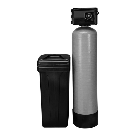
Pre-installation Instructions Description of the water softener system This water softener system includes a brine (salt) tank and a resin (media) tank with a backwashing control valve. Incoming water flows into the control valve and is directed down through the ion exchange softening resin. - Page 4 Location Considerations The proper location to install the water softener system will ensure optimum performance and satisfactory water quality. The following factors should be considered in selecting the location of the equipment. 1. The water softener should be installed after the pressure tank (private well system only). 2.
-
Page 5: Installation
Use clips and screws provided and attach bypass valve to the inlet/outlet of the control valve (FS Series) or meter module (FSM Series). Please note that FSLM units have the meter attached to the bypass valve rather than the control valve for shipping. -
Page 6: Brine Tank
FIGURE 3: Brine Tank Brine Line To Brine Valve on Control Valve Safety Brine Valve Brine Tank Overflow Elbow Safety Float Brine Overflow Drain Line (Not included) To Floor Drain Salt Platform Brine Well Air Check STEP 8: Install overflow tubing from overflow elbow on brine tank to floor drain. Tubing must be lower than overflow elbow at all times to brine tank overflow in case of malfunction. - Page 7 STEP 13: Turn power or fuel supply back on to water heater. STEP 14: Set the regeneration frequency (refer to timer operation for instruction). STEP 15: Set the current time of day on the timer (note AM and PM). STEP 16: Fill brine tank with salt and add approximately 6 gallons of water for the initial regeneration cycle.
-
Page 8: Fs Time Clock Timer Setting
FS Series Time Clock Setting Instructions Timer Operation FIGURE 5: Front of Time Clock Timer Assembly How to set Time of Day: 1. Press and hold the red button to disengage the 24 hour gear. 2. Turn the large 24 hour gear until the actual time of day is at the time of day arrow. - Page 9 Adjusted Hardness -- Grains per Gallon People TABLE 1: Model Number FS24, FSL24 Adjusted Hardness -- Grains per Gallon People TABLE 2: Model Number FS30, FSL30, FSI34 Adjusted Hardness -- Grains per Gallon People TABLE 3: Model Number FS45, FSI48...
- Page 10 Adjusted Hardness -- Grains per Gallon People TABLE 4: Model Number FS60, FSI68 Adjusted Hardness -- Grains per Gallon People TABLE 5: Model Number FS75...
-
Page 11: Fsm Meter Setting
FSM Series Meter Setting Instructions FIGURE 6: Front of Meter Timer Assembly How to set Time of Day: 1. Press and hold the red button to disengage the 24 hour gear. 2. Turn the large 24 hour gear until the actual time of day is at the time of day arrow. 3. -
Page 12: Fs & Fsm Adjust Time Of Regeneration
FS & FSM Series Adjustable Regeneration Time Instructions FIGURE 7: Front of Timer Assembly (Time Clock Assembly Shown) How to Adjust Regeneration Time: 1. Disconnect the power source. 2. Locate the three screws behind the manual regeneration knob by pushing the red button in and rotating the 24 hour dial until each screw appears in the cut out portion of the manual regeneration knob. - Page 13 This page intentionally left blank.
-
Page 14: Unit Model Specifications
Specifications UNIT MODEL NUMBER FSL24 FSL30 FS24 FS30 FS45 FS60 FS75 FSLM24 FSLM30 FSM24 FSM30 FSM45 FSM60 FSM75 MEDIA VOLUME, ft (liters) 0.75 0.75 (21) (28) (21) (28) (42) (57) (71) CAPACITY, grains (grams) @Factory Salt - 9lb/ft (146 g/L) 18,000 24,000 18,000... - Page 15 Specifications UNIT MODEL NUMBER FSL24-HE FSL30-HE FS24-HE FS30-HE FS45-HE FS60-HE FS75-HE FSLM24-HE FSLM30-HE FSM24-HE FSM30-HE FSM45-HE FSM60-HE FSM75-HE MEDIA VOLUME, ft (liters) 0.75 0.75 (21) (28) (21) (28) (42) (57) (71) CAPACITY, grains (grams) @Factory Salt - 6lb/ft (96 g/L) 20,250 27,000 20,250...
- Page 16 Specifications UNIT MODEL NUMBER FSI34 FSI48 FSI68 FSIM34 FSIM48 FSIM68 MEDIA VOLUME, ft (liters) (28) (28) (42) CAPACITY, grains (grams) @Factory Salt - 9lb/ft (146 g/L) 24,000 36,000 48,000 (1,555) (2,333) (3,110) @Max. Salt - 15lb/ft (243 g/L) 30,000 45,000 60,000 (1,944) (2,916)
- Page 17 This page intentionally left blank.
-
Page 18: Component Parts Breakdown & List
Component Parts Breakdown Model Number Description FSL24 FSL30 FS24 FS30 FS45 FS60 FS75 FSLM24 FSLM30 FSM24 FSM30 FSM45 FSM60 FSM75 Timeclock Valve FSL24 Vlv Assy FSL30 FS24 Vlv Assy FS30 Vlv Assy FS45 FS60 FS60 w/ 3/4” stainless W/BP Assy W/BP W/BP W/BP Assy W/BP... - Page 19 Model Number Description FSL24-HE FSL30-HE FS24-HE FS30-HE FS45-HE FS60-HE FS75-HE FSLM24-HE FSLM30-HE FSM24-HE FSM30-HE FSM45-HE FSM60-HE FSM75-HE Timeclock Valve FSL24-HE FSL30-HE FS24-HE FS30-HE FS45-HE FS60-HE FS60-HE w/ 3/4” stainless Assy W/BP Assy W/BP Assy W/BP Assy W/BP Assy W/BP Assy W/BP Assy W/BP steel bypass Metered Valve w/...
-
Page 20: Fs Control Valve Breakdown
FS (Time Clock) Control Valve Breakdown... -
Page 21: Fs Control Valve Parts List
FS (Time Clock) Control Valve Parts List Part REF # Part Number Description REF # Description Number 1.5 GPM DLFC 60040SS Stainless Steel Bypass, ¾” FPT 12086 (FS24, FSI34) 2.4 GPM DLFC 60041SS Stainless Steel Bypass, 1” FPT 12088 (FSL24, FS30, FSI48) 3.0 GPM DLFC 60900-41 Coupling Kit... -
Page 22: Fsm Control Valve Breakdown
FSM (Metered) Control Valve Breakdown... -
Page 23: Fsm Control Valve Parts List
FSM (Metered) Control Valve Parts List Part REF # Part Number Description REF # Description Number 1.5 GPM DLFC 60040SS Stainless Steel Bypass, ¾” FPT 12086 (FSM24, FSIM34) 2.4 GPM DLFC 60041SS Stainless Steel Bypass, 1” FPT 12088 (FSLM24, FSM30, FSIM48) 3.0 GPM DLFC 60088 Meter Module, Rt Angle, Std Rge... -
Page 24: Troubleshooting
Troubleshooting PROBLEM CAUSE SOLUTION A. Ensure permanent electrical service A. Electrical service to unit has been to unit (switch, circuit breaker, plug, interrupted etc.) B. Faulty timer motor or micro switch B. Replace defective component 1. Softener fails to regenerate C. - Page 25 Troubleshooting (continued) PROBLEM CAUSE SOLUTION A. Clean or replace injectors and A. Injectors or screen plugged screen B. Restricted drain flow control B. Clean drain line flow control 8. Salty water after regeneration C. Brine valve sticking C. Replace brine valve assembly D.
-
Page 26: Ten Year Limited Warranty
TEN YEAR LIMITED WARRANTY WARRANTY – First Sales, LLC. warrants this water conditioner against any defects that are due to faulty material or workmanship during the warranty period. This warranty does not include damage to the product resulting from accident, neglect, misuse, misapplication, alteration, installation or operation contrary to printed instructions, or damage caused by freezing, fire, flood, or Acts of God.
Need help?
Do you have a question about the FS Series and is the answer not in the manual?
Questions and answers