Table of Contents
Advertisement
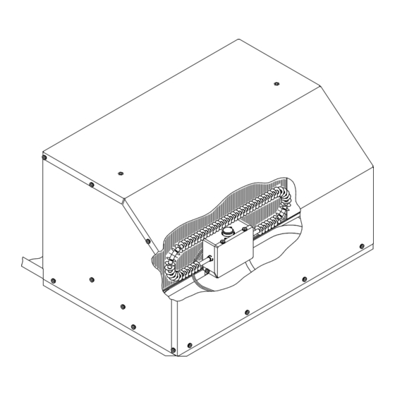
9330F4552 FREE DELIVERY PLENUM KITS
8330-752 CONTROL BOX KIT (12 VDC COOL ONLY)
9330C755 CONTROL BOX KIT (12 VDC HEAT READY)
8530-750 CONTROL BOX KIT (24 VAC COOL ONLY)
9530A751 CONTROL BOX KIT (12 VDC HEAT PUMP)
9430A751 ZONE CONTROL KIT (12 VDC COOL ONLY)
9430A755 ZONE CONTROL KIT (12 VDC HEAT READY)
9630A751 ZONE CONTROL KIT (12 VDC HEAT PUMP)
Coleman is a registered trademark of The Coleman Company, Inc. used under license. Mach is a registered trademark.
1976N350 (9-14) PP
RV Products Division
INSTALLATION INSTRUCTIONS
RV Products Division
Wichita, KS 67204
FOR
Airxcel, Inc.
P.O. Box 4020
Advertisement
Table of Contents


Need help?
Do you have a question about the 9330F4552 and is the answer not in the manual?
Questions and answers