Table of Contents
Advertisement
9330F4552 FREE DELIVERY PLENUM KITS
8330-752 CONTROL BOX KIT (12 VDC COOL ONLY)
9330C755 CONTROL BOX KIT (12 VDC HEAT READY)
8530-750 CONTROL BOX KIT (24 VAC COOL ONLY)
9530A751 CONTROL BOX KIT (12 VDC HEAT PUMP)
9430A751 ZONE CONTROL KIT (12 VDC COOL ONLY)
9430A755 ZONE CONTROL KIT (12 VDC HEAT READY)
9630A751 ZONE CONTROL KIT (12 VDC HEAT PUMP)
Coleman is a registered trademark of The Coleman Company, Inc. used under license. Mach is a registered trademark.
1976N350 (9-14) PP
RV Products Division
INSTALLATION INSTRUCTIONS
RV Products Division
Wichita, KS 67204
FOR
Airxcel, Inc.
P.O. Box 4020
Advertisement
Table of Contents

Related Manuals for Coleman 9530A751


Summarization of Contents
Warnings and Safety Precautions
Shock Hazard Warning
Warning about severe personal injury or equipment damage due to electrical shock during installation.
General Information and Requirements
Qualified Personnel
Personnel must be qualified and may require licensing by some states.
Air Distribution Design
System designed for free delivery air distribution, applicable to specific roof top unit series.
Low Temperature Probe Functionality
Probe monitors evaporator coil temp, stopping compressor below 28F and resuming at 55F.
Package Contents and System Match-Up
Package Contents List
Lists the items included in the mounting kit package.
System Compatibility Guide
Details compatibility between ceiling assemblies, control box kits, and wall thermostats.
Ceiling Plenum Installation Requirements
Standard Control Box Wiring
Details terminal connections and functions for standard control boxes.
Zone Control Box Wiring
Details terminal connections and functions for zone control boxes.
Control Box Kits and Thermostat Wiring
Control Box Kit Descriptions
Details the components included in various control box kits.
Zone Control Box Kit Descriptions
Details the components included in various zone control box kits.
Wall Thermostat Installation
Instructions for locating and installing the wall thermostat.
Thermostat Wiring Routing
Guidelines for routing thermostat 12 VDC supply and low voltage control wiring.
Wiring Routing Procedures
Zone Thermostat Wiring Routing
Route zone thermostat control wiring and follow Airxcel's low voltage wiring specifications.
115 VAC Wiring Routing
Route 115 VAC supply wiring from source to wirebox, following electrical codes.
High Voltage Wiring Specs (Min Amperage)
Guidelines for copper conductor sizing based on minimum overcurrent protection device amperage.
High Voltage Wiring Specs (Higher Rating)
Guidelines for copper conductor sizing based on higher rated overcurrent protection devices.
Securing Upper Unit to Roof
Mount Gasket Placement
Locate the upper unit mount gasket over the 14" to 15" square opening in the roof.
Ceiling Assembly Mount Frame Installation
Install the ceiling assembly mount frame using the four provided bolts.
Bolt Tension Achievement
Achieve proper tension for each bolt when gasket indicating tab is pulled down even with the roof.
Control Box Installation
8330-752 Control Box Wiring
Illustration showing thermostat wire connections for control box 8330-752.
9330C755/9530A751 Control Box Wiring
Illustration showing thermostat wire connections for control boxes 9330C755 and 9530A751.
8530-750 Control Box Wiring
Illustration showing thermostat wire connections for control box 8530-750.
115V Conduit Connection
Connect the roof unit 115V conduit to the wirebox 9-pin receptacle and verify alignment.
Securing Control Box to Unit
Secure the control box to the upper unit enclosure using machine screws and wing nuts.
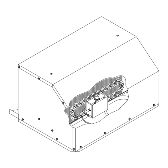
Evaporator Freeze Sensor Insertion
Instructions for inserting the evaporator freeze sensor between fins for accurate temperature monitoring.
Zone Control Box Installation
Zone Jumper Setting
Set the 'zone' jumper to the correct position for the air conditioner or heat pump's zone.
Heat Pump (HP/NON HP) Jumper
Set the 'HP'/'NON HP' jumper based on whether the unit is a heat pump or not.
Field Lead Wire Routing
Feed field lead wires and ground through the strain relief and into the control box.
Zone 1 Thermostat Wiring
Connect thermostat wires to the Zone 1 control box according to the provided illustration.
Heater Assembly and Wiring
Electric Heater Positioning (48000/49000)
Position the electric heater assembly in the return air opening for 48000/49000 series units.
Heater Umbilical Connection
Connect the heater umbilical's two-pin connector to the control box receptacle.
Wiring Securement
Ensure all wiring is tied securely to prevent contact with sharp edges or high velocity air.
Ceiling Assembly Installation
Duct Collar Fastening
Fasten the duct collar to the basepan of the air conditioner with three screws.
Ceiling Assembly Mounting
Raise and secure the ceiling assembly to the mounting frame with shoulder screw/spring assemblies.
Shroud Adjustment for Ceilings
Adjust ceiling assembly shroud for crowned ceilings or use optional screws for flat ceilings.
Filter and Grille Installation
Ensure non-allergenic filters are properly positioned in the ceiling grille and install the grille.
Need help?
Do you have a question about the 9530A751 and is the answer not in the manual?
Questions and answers