Table of Contents
Advertisement
Quick Links
Kit Part Numbers 30400-KIT, 30401-KIT, 30402-KIT, 30403-KIT
Thank you for choosing FAST™ products; we are proud to be your manufacturer of choice. Please
read this instruction sheet carefully before beginning installation, and also take a moment to review the
included limited warranty information.
Please begin by checking that you have received all of the parts that come with your kit.
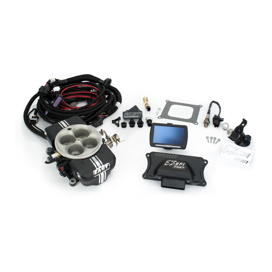
30400-KIT – EZ-EFI
QTY
1
1
1
1
1
®
EZ-EFI
2.0 Self Tuning
®
2.0 Base Kit
PART#
304151MCAS
30326
30633
30308
30310
Fuel Injection System
DESCRIPTION
EZ‐EFI 2.0® Assembled Throttle Body
EZ‐EFI 2.0® ECU Module
EZ‐EFI 2.0® Touchscreen Hand‐held Unit
Harness, EZ‐EFI 2.0® Main
Harness, EZ‐EFI 2.0® Hand‐held Cable
INSTRUCTIONS
1
Advertisement
Table of Contents
Troubleshooting

Related Manuals for Fast 30400-KIT-EZ-EF


Summary of Contents for Fast 30400-KIT-EZ-EF
- Page 1 Fuel Injection System Kit Part Numbers 30400-KIT, 30401-KIT, 30402-KIT, 30403-KIT Thank you for choosing FAST™ products; we are proud to be your manufacturer of choice. Please read this instruction sheet carefully before beginning installation, and also take a moment to review the included limited warranty information.
- Page 2 1 170637 Tach Adapter Assembly, FAST™ 1 30087 Sensor, Coolant Temp 1 30278 Brass Bushing, 1/2"MPT X 3/8"FPT 1 170408 O2 Sensor, Bosch LSU4 Wideband 1 30168 Weld in O2 Fitting 1 30169 O2 Sensor Plug 1 82042 Gasket, Square Bore Carb 12 NS6548 Tie Strap, Black 4 30291 Screw, #12x1" LG.,Self Tap,SS 1 304150TBJ Throttle Ball Join, Linkage, for 304150 1 304150TBJNUT Nut, 1/4"‐28, Nylon Lock (for 304150TBJ) 1 30428 Sensor, Fuel Pressure, EZ EFI 2.0 1 30425FSB Fuel Pressure Sensor Adapter 1 ...
- Page 3 QTY PART# DESCRIPTION 1 307034 450 LPH In‐Tank Fuel Pump 1 307035 In‐Tank Pump Pre‐Filter 1 307036 In‐Tank Pump Pigtail 1 30272 Fuel Filter, ‐6AN Black 1 30313 Harness, EZ‐EFI® FP Relay Solid State 1 54027G Fuel Pressure Gauge, FAST 0‐100 PSI 7 30275 Fitting, ‐6AN Straight Push Lock End 4 30276 Fitting, ‐6AN 90Deg Push Lock End 25 30295 Hose, Fuel Injection, 3/8"OD x 1' SAE30R9 12 30295‐HC Hose Clamp, For 30295 FI Hose 1 307030 Fuel Pressure Regulator, 30‐70 psi Adj. 2 30251 Fitting, ‐6AN to Straight Oring ‐6AN 1 ...
- Page 4 1 NS6601 Fuel Pump, In‐Line 1 30272 Fuel Filter, ‐6AN Black 1 NS6602 Bracket, for In‐Line Pump 1 NS6603 Hardware Kit, In‐Line Pump 2 30250 Fitting, ‐6 Male x 10mmx1.0 Thread, Black 1 30313 Harness, EZ‐EFI® FP Relay Solid State 1 54027G Fuel Pressure Gauge, FAST 0‐100 PSI 1 30274 Fitting, AN6 to AN6 Female Coupler 6 30275 Fitting, ‐6AN Straight Push Lock End 2 30276 Fitting, ‐6AN 90Deg Push Lock End 1 30295 Hose, Fuel Injection, 3/8"OD x 25’ SAE30R9 10 30295‐HC Hose Clamp, For 30295 FI Hose 1 307030 Fuel Pressure Regulator, 30‐70 psi Adj. 2 ...
- Page 5 For this reason, you will need to install a new fuel injection-rated fuel system in your vehicle. If you purchased a 30401-KIT or 30402- KIT 55 Master Kit, or one of the FAST™ fuel kits, then you have everything you need to make the switch.
- Page 6 If you need a new system, consider the FAST™ 304147 kit. It is designed specifically for this application. If your vehicle has a 700R4 transmission, you will also need a cable corrector kit such as ®...
- Page 7 (NOTE: If you will be installing a new distributor, such as the FAST™ Dual Sync Distributor, you may have more room to work if you complete the first part of that installation before bolting down the throttle body.)
- Page 8 6. When your entire installation is finished, be sure to install an air cleaner onto your throttle body (using the stud from the carburetor that you removed.) Standard carburetor-style air cleaners fit ® the EZ-EFI throttle body or check out FAST™ PN 30420 for the matching air cleaner to your ® EZ-EFI throttle body.
- Page 9 In-tank vs In-line: In-tank pumps are preferred over in-line pumps for multiple reasons. Most importantly, in-tank pumps do not experience the priming issues that can sometimes occur with in-line pumps. In-tank pumps can be found on practically all late model cars due to their simplicity and effectiveness, and as stated above, are required for returnless-style fuel systems.
- Page 10 2. With the sending unit out, remove the old fuel pump and replace with your new pump. Two 40-60mm hose clamps are included with the FAST™ in-tank fuel kits to order to mount the pump. A sock-type pre-filter is also provided and should be connected to the bottom of the pump.
- Page 11 In-Tank Fuel Pump System Layout...
- Page 12 To assemble hoses, use the following procedure. 6. Cut hose to the desired length using a fine tooth saw or cut-off wheel. Be sure to clean the cut edges of any loose material. 7. Lube the barbed end of the fitting with a light oil such as WD-40. 8.
- Page 13 11. Slide the hose clamp over the barbed section and tighten. Fuel Pressure Regulator Installation (only used for return style systems): 12. Install the two supplied -6AN fittings. One will be installed in the bottom of the regulator (outlet/return port), and the other will be installed in one of the inlet ports on the side of the regulator (choose either side based on easiest hose routing in your application.) The unused inlet port on the other side should be blocked off with the included plug.
- Page 14 14. With the regulator now preassembled, mount using the supplied mounting bracket and screws. 15. Finally be sure to connect the barbed fitting to the manifold vacuum port on the throttle body using the supplied 1/8" vacuum hose. Manifold Vacuum Port Labeled “A”...
- Page 15 In-Tank Fuel Pump Wiring: Wiring needs to be passed into the tank to power the pump. A sealed bulkhead fitting and other wiring components are supplied for this purpose. Some of the final assembly is left for the user to complete to custom fit the installation to their vehicle.
- Page 16 Follow the diagram below for proper installation. Keep in mind that the fuel pump included with the FAST™ kit features an integrated pre-filter. If you run a different pump without a pre-filter, be sure to install a pre-filter in-line before the pump.
- Page 17 In-Line Pump Fuel System Layout...
- Page 18 In-Line Fuel Pump Wiring: Wiring components for connecting power and ground to the fuel pump are supplied. Some of the final assembly is left for the user to complete to custom fit the installation to their vehicle. Wiring Assembly: 1. The kit includes two small, blue ring terminals. Crimp one onto the red “PUMP POSITIVE” feed wire from the fuel pump relay harness and the other to one end of the supplied length of loose black wire.
- Page 19 NOTE: Installing the threaded oxygen sensor fitting should be the first step in the installation process. It should be done before you begin removing your existing fuel/induction system. That way, you can still drive to an exhaust shop if needed. Wideband Oxygen Sensor Installation Notes: ...
- Page 20 The Coolant Temperature Sensor monitors engine coolant temperature. It is typically installed in an existing mounting hole on the top of the intake manifold. The sensor has 3/8" NPT threads. The supplied adapter may be required to install the sensor in some manifolds with 1/2" NPT threads. The engine block or cylinder head may have a provision for mounting a coolant temperature sensor.
- Page 21 problems with electrical noise. These kinds of problems are difficult to diagnose. The wires may be extended if needed using automotive grade 10 gauge (or larger) wire. Yellow ring terminals are included for making the battery connections. After the ring terminals have been crimped on, use a heat gun or other heat source on the insulation to shrink it and seal it to the wire.
- Page 22 CAN enabled devices: FAST™ EZ‐LS™, FAST™ CAN Link XIM™, TCI® EZ‐TCU™, etc. Configurable Gray/Black Reserved for future use. Input Configurable Blue/Yellow Reserved for future use. Output Coolant Temperature Sensor (CTS) typically Coolant Temp installed in intake manifold. (This lead comes from the throttle body harness.) FAST™ Crank Trigger or other 2‐wire inductive pickup. This is one option for a crank reference input to allow EZ‐EFI® to control ignition timing. See Ignition System Options for more Crank Trigger details. If this connector is being used, the “DISTRIBUTOR” connector and “RPM INPUT” wire will not be used. FAST™ Dual Sync Distributor connector or other discrete pickup. This is one option for a crank reference input to allow EZ‐EFI® to control ignition timing. This connector is also used to interface to a FAST™ EZ‐LS™ / FAST™ XIM™ ignition system for coil‐per‐ Distributor cylinder applications. See Ignition System Options for more details. If this connector is being used, the “CRANK TRIGGER” connector and “RPM INPUT” wire will not be used. FAST™ Dual Sync Distributor power wire. Distributor This feeds 12V switched power to a FAST™ ...
- Page 23 system. Negative control side of a relay for powering Fan 1 Relay Blue an electric fan. Do NOT wire directly to fan. Negative control side of a relay for powering Fan 2 Relay Blue/White a second electric fan. Do NOT wire directly to fan. Fuel Pressure Fuel pressure sensor. Fuel Pump EZ‐EFI® fuel pump relay harness included Harness / Relay with EZ‐EFI® fuel system kits. (multi‐pin) Negative control side of a relay for powering Fuel Pump a fuel pump. Do NOT wire directly to fuel Harness / Relay pump. Not used with pre‐wired EZ‐EFI® fuel (single‐pin) pump relay harness included with EZ‐EFI® fuel system kits. Hand‐held cable that links the main wiring Hand‐Held harness to the hand‐held user interface. Nitrous activation wire. Feeding power to Nitrous Input Gray/Red this wire tells the ECU that a nitrous oxide system has been activated. ...
- Page 24 Wideband oxygen sensor (O2) mounted in Oxygen Sensor exhaust. “Points” input on an ignition box to make it fire. Only used when EZ‐EFI® is controlling ignition timing. See Ignition System Options Points Output Brown for more details. If this wire is being used, the “RPM INPUT” wire will not be used, and vice versa. A tach output from an ignition box or other source. Or the EZ‐EFI® RPM Module. This is White the RPM input for the ECU when it is not controlling ignition timing. See Ignition System Options for more details. RPM Input Do NOT connect this wire directly to an ignition coil. See RPM Module notes. If this wire is being used, the “POINTS OUTPUT” wire, “CRANK TRIGGER” connector and “DISTRIBUTOR” connector will not be used. Throttle Body Pigtail on throttle body. Relay wiring: The switched outputs from the ECU are not meant to directly drive high-current devices such as fuel pumps or electric fans.
- Page 25 NOTE: The fuel pump relay used in the EZ-EFI® 2.0 fuel pump relay harness is a special solid state relay. It is compatible with return style fuel systems and required for returnless style fuel systems. Its wiring is different than standard relays. Ignition System Options The ignition system components that are needed and the wiring harness connections that will be used depend on the type of engine and whether or not the EZ-EFI®...
- Page 26 There are several ways to provide this. A. FAST™ Crank Trigger – The FAST™ Crank Trigger consists of a trigger wheel that attaches to the crank and a sensor that watches as the teeth pass by. Roll the motor over to TDC on #1 compression stroke.
- Page 27 Then clamp down the distributor and install the cap. 6. Your crank signal is now set and your rotor is phased. Because the FAST™ Dual-Sync Distributor is pre-phased at 30° BTDC, lining up the rotor tip and terminal with the engine at 30°...
- Page 28 2 Red Green In the Setup Wizard, select “FAST Crank Trigger / 2 Wire” on the Ignition Type screen. Rotor Phasing When using a crank trigger, the distributor’s orientation in the engine is not critical to the ECU. However, it is still important to phase the rotor to the cap. This will ensure that the rotor is in the correct position throughout the timing sweep in order to fire to the correct cylinder terminal.
- Page 29 be an opportunity to check the alignment and compensate for any misalignment with the hand-held later in this installation procedure. Pickup Paddle Wheel Align 5. Clamp down the distributor. 6. Next, it is important to phase the rotor to the cap. This will ensure that the rotor is in the correct position throughout the timing sweep in order to fire to the correct cylinder terminal.
- Page 30 RPM away from the commanded value. “CRANK TRIGGER” FAST™ MSD DISTRIBUTOR CONNECTOR PIN # WIRE COLOR WIRE COLOR 1 Black Black/Orange 2 Red Black/Violet In the Setup Wizard, select “FAST Crank Trigger / 2 Wire” on the Ignition Type screen.
- Page 31 Modern coil-per-cylinder engines have complex crank and cam trigger wheels. FAST™ EZ-LS™ and FAST™ XIM™ ignition systems read in and decode the factory crank and cam signals to give the EZ- EFI® engine speed and position. The FAST™ EZ-LS™ and FAST™ XIM™ ignition systems also drive the coils.
- Page 32 RPM Module ® EZ-EFI is an advanced fuel injection system. Engine speed is one of the fundamental elements of its fueling calculations. When not controlling ignition timing, it relies on the vehicle’s existing ignition system for a steady, reliable RPM signal. An inconsistent or noisy RPM signal can appear to the ECU as erratic engine speed.
- Page 33 ® disabling it. Keep in mind that it is normal for the EZ-EFI system’s “pre-squirt” feature ® (discussed in the EZ-EFI SYSTEM FEATURES section) to pulse the injectors for a second or two right at key-on. This feature can be distinguished from a potential ignition issue in several ways: ...
- Page 34 ® INPUT” wire in the EZ-EFI wiring harness directly to that terminal. The ECU will be damaged. In a case like that, the RPM Module is required since what you are really doing is connecting to the negative side of a dwell-controlled coil. ...
- Page 35 display. The result is that where you see a “button” on the screen is also where you need to touch to select it. This calibration is performed at the factory. It is unlikely that it will ever need to be repeated. Home Screen Setup Wizard The Setup Wizard is a guided configuration process used for initial setup.
- Page 36 Setup Wizard Setup Wizard Notes Running the Setup Wizard will overwrite the previous configuration and any user adjustments that have been made. It will also erase any learning that has taken place. The ECU will be restored to its factory “stock” settings. ...
- Page 37 Engine Parameters To adjust a setting, touch the Engine Cubic Inches, Idle RPM or Rev Limit textbox. Then enter desired numbers on the keypad and press Ent. The value will be sent to the selected textbox. Number of cylinders – Choose from 4, 6, or 8. The button’s LED will indicate selection. ...
- Page 38 Once RPM has dropped, injection will resume. NOTE: Keep in mind that the Rev Limiter will prevent the engine from spinning itself too fast under its own power. But it does not protect against something else spinning the engine too fast –...
- Page 39 FAST Distributor – Select if using a FAST™ Dual-Sync Distributor or other discrete, square wave-type RPM signal. FAST Crank Trigger / 2 Wire – Select if using a FAST™ Crank Trigger or other 2-wire inductive, sine-wave type RPM signal.
- Page 40 Idle – While the engine is at idle RPM, this will be the base timing. Keep in mind that both idle trim and vacuum advance (discussed later) can apply an offset to this base timing value. All-In – The maximum amount of timing used on the base timing curve. Timing will ramp up from Idle timing to All-In timing as RPM increases towards the All-In RPM.
- Page 41 Inglese™ Setup There are two main styles of Inglese™ systems: Down Draft (Eight-Stack) and Side Draft. If using a Down Draft system, select the kit based on rated horsepower of the kit or the injector part number. If a Side Draft system is used, choose between Single or Dual. Injector Specs To adjust a setting, touch the Injector lb/hr or Fuel Pressure PSI textbox.
- Page 42 65 56 / Fuel Pressure PSI – Enter the fuel pressure you will be using. If a returnless fuel system is being used, the ECU will control the fuel pump to maintain the pressure entered here. If a return-style fuel system is being used, this should be set to match the pressure the mechanical fuel pressure regulator will be set to.
- Page 43 off for the final time and the throttle can be released. The “Next/Confirm” button will become available. NOTE: The full throttle procedure is meant to be performed with the engine NOT running! Fuel System Test The fuel system test procedure differs slightly depending on the fuel system selected. Shown below are the two types of tests that may run.
- Page 44 If this happens and the vehicle really is using a return-style fuel system: 1. Turn the ignition switch off and wait for all of the LEDs on the ECU to turn off. 2. Back the adjustment screw on the regulator all the way out to lower the fuel pressure. 3.
- Page 45 After starting the engine, use a timing light to verify that the timing is correct. The ECU will lock the timing to 20° of advance during this test. That is what the timing light should show. If it doesn’t, use the Plus or Minus buttons to fine tune the ignition setup until the timing light does show 20°...
- Page 46 As mentioned above, with a traditional single coil engine using a crank trigger or distributor, the ECU expects crank signals at TDC (0° BTDC). When used with a FAST™ EZ-LS™ or FAST™ XIM™ ignition system, the ECU expects the crank signals at different locations depending on the make of the engine.
- Page 47 NOTE FOR 500C.I.D. or LARGER ENGINES: The idle motor’s entire range of movement is from 5 to 180 “counts. ”Higher counts mean the idle motor is open more and allowing more air to bypass the throttle blades. Adjusting the throttle blade so that the bar is roughly centered on the “target”...
- Page 48 Fan Control ® EZ-EFI has two electric fan outputs with independently adjustable Fan On Temperatures. Select the desired fan and adjust the activation point with the dial on the right hand side of the screen. Rotate the dial clockwise to raise the activation point and counter clockwise to lower the activation point. Fan Off Temperature is automatically adjusted up or down along with the Fan On Temperature.
- Page 49 will be sent to the selected textbox. (For E85 applications, you may only need to enter two digits. For example, enter “92” for a 9.2 air/fuel ratio.) The ECU is constantly working to keep the air/fuel ratio at the current target air/fuel ratio. It is preloaded with typical targets.
- Page 50 Just as the Cruise Air/Fuel target can be adjusted for fuel economy, the WOT Air/Fuel target can be adjusted for maximum power. It is quite possible that the engine can make more power at an air/fuel ratio that is leaner (higher number) than the preloaded WOT Air/Fuel target. Or it might prefer a richer (lower number) air/fuel ratio.
- Page 51 Accel Fuel is a fine-tuning detail to adjust how the engine responds to throttle changes. In general, it should only be adjusted after the ECU has had some time to learn and the engine is running well in ® steady-state operation - throttle not changing. An exception to this is when the EZ-EFI system is installed on a port-injected application where fuel is supplied by injectors near each intake port instead ®...
- Page 52 more or less cranking fuel, that adjustment can be made here. SETTING EFFECT Positive More cranking fuel Negative Less cranking fuel Cold Start After the engine has started, the ECU’s closed-loop fuel control will begin altering fueling to maintain the target air/fuel ratio. When the engine is cold, the target air/fuel ratio is adjusted to a richer (lower number) value.
- Page 53 Improper use of nitrous oxide systems can result in costly engine damage. Typical naturally aspirated engine air/fuel ratio targets and timing targets are unsafe for nitrous oxide use. Be sure you understand the proper configuration of nitrous oxide systems before deciding on these settings. When the ECU has detected the activation of a nitrous oxide system (by having power applied to the gray/red “NITROUS INPUT”...
- Page 54 Vacuum Advance An RPM-based timing curve is set on the Timing Setup screen. It is similar to mechanical advance on a traditional distributor. The Vacuum Advance feature is similar to a vacuum canister on a traditional distributor. It can add ignition advance based on manifold vacuum as read by the MAP sensor. This feature is disabled when the throttle is closed to mimic a traditional ported vacuum arrangement.
- Page 55 subtract to influence idle speed. Some engines may like more, some may like less. 5 degrees is usually a good starting point. The final ignition timing the engine sees (Total Timing) is composed of three components: Base Timing Value from RPM‐based timing curve + Idle Adv Timing added or subtracted to influence idle speed (Optional. See Advanced menu.) + Vacuum Adv ...
- Page 56 Dash 1 Dash 2 Dash 3...
- Page 57 Master Dash The Master Dash is designed for easy viewing of all sensors and user accessible values. For example, this dash may be used as an overview to quickly verify that all sensors are reading expected values. Also note that the ignition timing-related values are given along the bottom of the Master Dash – the three component parts as well as the end result.
- Page 58 Degrees of ignition timing added or subtracted by the ECU (if enabled) to influence idle speed. This makes up one part of the final timing value the engine sees. Idle Adv Base Timing + Idle Adv + Vacuum Adv = Total Timing Timing‐related data is only valid when EZ‐EFI® is controlling timing. Injector duty cycle. This is a comparison of how long the injectors are open compared to how much total time is available for them to be open. At higher RPM, there is less Inj DC % time between injector openings. If this reaches 100%, it means the injectors physically cannot flow any more fuel. They are already being held wide open. Current total fuel flow rate into the engine. Given in pounds per hour. This can be Lb/Hr ...
- Page 59 Diagnostics Codes When an error code is set, the blue CRANK/DIAG LED on the ECU will flash rapidly and the “Error” LED displayed on the hand-held’s Live Dashes will turn on. If that happens, use this screen to find out which code has been set.
- Page 60 Tech Support Provides a list of resources for getting answers to your questions. System Info IRM Counts The Ignition Reliability Monitor number gives a relative indication of the stability of the RPM signal being fed into the ECU. It is a running total of RPM signal errors the ECU has detected. A higher number indicates a noisier RPM signal.
- Page 61 wideband oxygen sensor provides very accurate feedback to the ECU so it knows if more or less fuel is needed to achieve the desired air/fuel ratio. Adjusting the fueling based on feedback from an oxygen sensor is commonly referred to as “closed-loop” fuel control. Closed-loop fuel control is a very powerful feature.
- Page 62 Learning does not begin until the engine is warmed up. Coolant temperature must be above 140° F for learning to begin. There are various qualifying conditions that must be satisfied for learning to take place. This prevents the ECU from learning from inappropriate feedback. Many of the learning qualifiers have to do with making sure the engine is in a steady state condition –...
- Page 63 0, the TPS should be re-calibrated. This can be done by selecting TPS Calibration from the Advanced menu. It is normal for fuel pressure to rise and fall with varying engine load. Fuel pressure will be lower at idle and in normal driving when there is more vacuum in the intake manifold. Fuel pressure will rise as the engine approaches wide open throttle.
- Page 64 On-Board Diagnostics ® The EZ-EFI system includes a robust self-diagnostics feature. The ECU constantly monitors various inputs and outputs for any deviations from normal operation. If any are detected, the blue CRANK/DIAG LED on the ECU flashes rapidly as a warning that there is a problem. (That LED comes on solid when the ECU detects an RPM input.
- Page 65 Wideband oxygen sensor unable to initialize, disconnected or O2 Sensor malfunctioning TPS Voltage Throttle Position Sensor signal voltage too high or too low Troubleshooting O2, IAC, Fuel Pressure Sensor, MAP, TPS, ATS and CTS Faults 1. Verify that the offending sensor is installed and connected to the wiring harness. 2. With the ECU keyed-on, use the hand-held to look for a valid reading from the offending sensor.
- Page 66 6. Verify all fuel line connections are tight and leak-free – including connections in the tank. 7. Verify that there is plenty of fuel in the tank. 8. Verify that the fuel filters (including the sock-type filter in the tank) are not clogged. 9.
- Page 67 on circumstances and which sensor has failed, the change in the engine’s behavior may be very obvious or it may be hardly noticeable. If you notice any change in how the engine is running, it’s a good idea to check the blue CRANK/DIAG LED on the ECU (it will flash rapidly) or the “Error” LED displayed on the hand-held’s Live Dashes.
- Page 68 Complementary Parts- PART# DESCRIPTION 30401‐FK In‐Tank Fuel Kit 30402‐FK In‐Line Fuel Kit 30420 EZ‐EFI 2.0 Matching Air Cleaner (14 x 12 x 3) 3012001 EZ‐EFI 2.0 Matching SBC Valve Cover 3011011 EZ‐EFI 2.0 Matching BBC Valve Cover 3035001 EZ‐EFI 2.0 Matching SBF Valve Cover 304147 EZ‐EFI Cable Mount Kit TCI 370816 700R4 TV Cable Corrector and Cable Mount Kit TCI 376715 700R4 TV Cable Corrector Bracket 301270 SBC Crank Trigger for 7.00" Balancer 301280 SBC Crank Trigger for 8.00" Balancer 301180 BBC Crank Trigger for 8.00" Balancer 303565 SBF Crank Trigger for 6.562" Balancer 305005 SBC/BBC Dual‐Sync Distributor 305017 BBC Tall Deck Dual‐Sync Distributor 305007 SBF Dual‐Sync Distributor 305009 Ford Windsor Dual‐Sync Distributor 305010 FE Ford Dual‐Sync Distributor 305015 Ford 351C‐460 Dual‐Sync Distributor 305011...
Need help?
Do you have a question about the 30400-KIT-EZ-EF and is the answer not in the manual?
Questions and answers