
Subscribe to Our Youtube Channel
Related Manuals for M2M Router PRO


Summary of Contents for M2M Router PRO
- Page 1 M2M Router PRO ® User Manual v1.7 _________________________________________ Rev: 1.7 2017-03-03...
-
Page 2: Document Specifications
Document specifications This document was completed for the M2M Router PRO ® device and contains the detailed description of the device configuration which is necessary for the proper operation of the device. You can choose 2G, 3G, and LTE versions of the modem types. All of the listed settings are similar for the modem versions. -
Page 3: Starting Up The Router
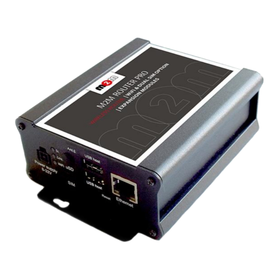
1. Starting up the Router 1.1 Cable connection 1. Mount a 2G/3G or two LTE SMA antenna – according to the module type - to one of the Antenna titled SMA-M interfaces (in case of LTE module all the two antenna must be mounted). - Page 4 1.2 First starting of the router 1. Plug the 12V DC power adapter chord to the POWER interface, then plug the adapter to the 230V electrical network. 2. The router has a pre-installed system (contains uploaded firmware and system software). By plugging the power adapter to the 230V AC socket, the router begins to work, whereas its LED signals are showing the current activity during the operation.
- Page 5 2. Allow the accessing of the router default IP address in your browser by pushing to the Special button, then allow the safety exclusion into the pop-up window. 3. The LuCi web user interface (OpenWrt) login data are the following: root wmrpwd Username:...
- Page 6 2. Router configuration on the OpenWrt user interface 2.1 Login 1. Login with: Username: root Password: wmrpwd then push to the Login button. 2. After login to the web interface, the startup screen appears with the current status of the router.
-
Page 7: Status Menu
2.2 Menu By the menu you can access the following features: Status – Status data, operation logs, operation monitoring System – System settings, administration, software and fw-refresh, backup/restrore of the configuration settings Router – Device Manager settings, Modem and Logging parameters, Ping an IP address, Daily restart, Factory settings Services –... -
Page 8: Router Menu
2.5 Router menu You can define the remote monitoring software connection settings of the az M2M Device Manager. Then at the Modem parameters (define special parameters for the connection). Define the Logging parameters. At the Periodic Ping you can configure the cyclic heartbeat ping interval settings – as a network checking method feature. -
Page 9: Network Menu
2.7 Network menu Here you can configure the settings of each network Interfaces You can check the WiFi connected devices at the WiFi item. You can modify the DHCP and DNS settings, or define the router network device name at the Hostname. ... -
Page 10: Interface Settings
3. Network configuration of the router 3.1 Interface settings The list of the available network interfacescan be found at the Interfaces / Interface Overview menu item. eth0 interface meaning the Ethernet port connection ( ), the interface is the public 3g-wan, in case of LTE: eth1 wireless Internet connection (as ) –... - Page 11 At the upper WAN, WIFI, LAN titles you will found further settings related to the chosen interfaces. 3.2 Mobile internet settings (modem) Open the WAN item from the upper selection. Then at the General Setup tab you can see the current status of the interface and the transmitted data amount.
- Page 12 The available APN settings will be assured by the SIM card provider mobile operator or your mobile internet service provider. Here you will found some examples for the APN settings. M2M APN (enclosed) APN name: wm2m Public Internet APN (opened)
- Page 13 When you are attempted to use a DUAL-SIM version router This can be used well as an alternative – or spare - network path, when the operation can be granted with better change instead of the field coverage (adding further mobile operator service).
-
Page 14: Wifi Settings (Optional)
3.3 WiFi settings (optional) Choose the WiFi option from the menu, then at the General Setup tab you can define a different IP address range for the IPv4 address. The WiFi feature is optiona for the router. In case of presense of the WiFi, the default mode is the AccessPoint, where clients can connect to the router. - Page 15 Under the Advanced Settings tab the Bring up on boot feature must be active (which initializes the 3G module when the router is booting), and the Use default gateway also must be active as the usage of Use DNS servers advertised by peer switch. When you modified the settings, save them by the Save &...
- Page 16 You can define further SSID by the . or edit the settings of the current one.
-
Page 17: Ethernet (Lan) Settings
The WiFi interface settings can be seen at the Interface part. The ESSID is the name of the Access Point (will be listed for the clients under this name). Therefore the wireless devices can discover and found it, connect to the router by the WiFi password. In case of more routers the reconfiguration of the SSID is recommended, which can be initiated by the button. - Page 18 The detailed LAN interface settings can be performed by the Network Interfaces menu itemat the LAN interface button. Change the default 192.168.127.1 router IPv4 address to an own IP address, regarding the current subnet. Check the IPv4 netmask to be proper for the selected and required network class which you are attempted to use.
- Page 19 3.5 DHCP, DNS settings At the Network menu, at the DHCP and DNS item, General Settings tab you can setup these. The DHCP service allows the automatic IP address providing for the connecting devices in the current IP segment by the router. Attention! You have to enable the DHCP service for these settings! The Start field means the starting IP addres in the subnet for the connecting devces (by default 192.168.x…).
- Page 20 The router will be providing IP addresses for the connecting devices in the 192.168.x subnet Start Start+Limit within the and between the address range (especially important for WiFi).
- Page 21 Disable DHCP for this interface If you attempted to disable the DHCP service, then choose the option at the Ignore Interface. When you modified the settings, save them by the Save & Apply button. The further DHCP server settings can be found at the Network menu, DHCP and DNS item. Here, at the lower Static Leases part you can devices to always provide the same dedicated IP address by the router.
-
Page 22: Firewall Settings
3.7 Firewall settings By default, the firewall is activated, but it allows all communication – so it is not filtered. in case of necessary, the access or the traffic can be limited by the ports, IP-segments or addresses. In the Network menu, at the Firewall item, General Settings tab you can configure the current firewall rules. - Page 23 When you modified the settings, save them by the Save & Apply button. The firewall can allow or tilt every communication by defauult – according to the further settings. Therefore just enabling the firewall feature does not protects the router from external attacks, intrusions.
- Page 24 3.8 Port Forward settings Here in the Network menu, at the Firewall item, Port Forwards tab you can setup, that which port forwarding rules should be valid. Here you can add the necessary ports and IP adresses. You can add a new rule by the button.
- Page 25 3.9 IP routing, NAT settings In the Network menu, Firewall item, Traffic Rules tab you can setup the Traffic Rules, and the Source NAT settings. You can add a new rule by the button. When you modified the settings, save them by the Save &...
- Page 26 The Source NAT settings can be performed for each protocol (tcp, udp), that the router allows the redirection of data –which incoming IP address and port must be redirected to which outgoing IP address and port and must be forwarded the data traffic. You also can define a port range, hereby. These rules must always be defined, not disallowing the general communication and must consider that the router must be further available on the network.
-
Page 27: Dynamic Dns Settings
Always check the used standard ports by the network services and allow these (e.g. FTP: port 21, SSH/Telnet: port 22, web: port 80, general network traffic on windows: 443, etc.). The proper port filtering, routes are minimizing the communication, what could be important by safety reasons, and could decrease the open threads and risks of safety leaks. -
Page 28: Special Settings
The main importants are the DM IP Address, the DM Port Number and DM User Name. These must be also configured in the Device Manager and the router must access the IP address of the M2M Device Manager. You can check it by performing a ping. 4.2 Monitoring the modem At the Router / Modem Parameters menu you can define some special operation monitoring and listener parameters for the modem. - Page 29 APN zone (e.g. from an enclosed APN zone the router will not access the public internet, and from the public internet it will not access the enclosed M2M APN zone). In case of M2M APN the 192.168.1.250 address can be accessed, it is possible to ping the address for checking the 3G network connection.
- Page 30 4.4 RS485/RS232 parameters In case of present of the serial port and RS485 port expansion, at the Services / Ser2net menu you can define the elements of the protocol conversion, such as receiving the incoming communication in the proper format and the transparent forwarding. 4.5 Network Time Service (NTP) Open the System menu, Time Synchronisation item.
- Page 31 At the Time Servers part you can NTP time servers by its Hostname, IP-address or server name, and Port. When you modified the settings, save them by the Save & Apply button. 4.6 Identifiying names connecting machines Open the Services menu, Hostnames item. Here you can register those machines, network devices which are using the router connection - for an easier identification.
- Page 32 4.7 TFTP service settings Open the Network menu, DHCP and DNS item, TFTP settings tab to allow the TFTP service (Enable TFTP server), and the related further parameters. When you modified the settings, save them by the Save & Apply button.
- Page 34 5. Software refresh and router maintenance 5.1 Firmware refresh 1. Open the System menu, Backup / Flash firmware item. fwos 2. Browse the -…. compressed file then push to the Flash image button. 3. A new window will appear where the file will be checked. When it is okay, the system refreshment is possible by the Proceed button.
-
Page 35: Installing Applications
4. Then the next message appears on the screen in the browser. Then the refresh method has started, while the LED2 and LED3 is continuously lidghting by red. 5. Later the LED2 wil blandk and only the LED3 lighting with red. 6. -
Page 36: Restarting The Router
5.3 Restarting the router Choose the System / Reboot item and push upon the Perform reboot button. Then the router will be restarted as it was described before (the 3 LEDs lighting shortly by colour for a second, and the St. LED flashing assigns the booting process, then the router will be operating as normal, and will be connected to the internet according the configuration settings. - Page 37 5.4 Reset When the router is not reacting or it was not possible to configure properly, push int he Reset titled low-case button for 10 seconds – by a sharp and thin object. Then the router will be restarted by the factory configuration, whereas the LED lights will assign it. After a few minutes, the router will be available and accessible on its default address.
- Page 38 The Restore backup is possible to reload – a previously saved configuration – when you will be able to browse and load from your computer to the router memory by pushing the button. 5.7 Handle of memory cards The router is able to handle the connected and mounted uSD cards, USB memory sticks. But these are only possible to access from the Linux command line (ssh connection).
-
Page 39: Troubleshooting
6. Troubleshooting LED activities Can you see a LED signal activity? It is not sure that after 2 minutes of LED inactivity it must mean a failure. It is possible that the router is currently under restart progress or it has just booting. Wait 2-3 minutes, then check the LEDs. - Page 40 Continuous restarting… When the modem is not available or cannot be connected to the network, then the router will be restarted in every 2 minutes! When the ppp/wan connection is not configured properly or the modem was not perperly confugzred, the router will be restarted in every 10 minutes. Antenna Check or connect proper SMA fit antenna to the Antenna connector and mount it to the interface.
-
Page 41: Support Availability
7. Support availability If you have any questions concerning the use of the device, contact us at the following address: E-mail: support@m2mserver.com Telephone: +36203331111 7.1 Contact the support line For the proper identification of the router you should use the sticker on the device, which contains important information for the call center. -
Page 42: Product Support
7.2 Product support The documentation and software released for this product can be accessed via the following link: http://www.m2mserver.com/en/products/m2m-router The documentation and software released for this product can be accessed via the following link: http://www.m2mserver.com/en/support/ Online product support can be required here:... -
Page 43: Legal Notice
8. Legal notice ©2017. WM Systems LLC. The content of this documentation (all information, pictures, tests, descriptions, guides, logos) is under copyright protection. Copying, using, distributing and publishing it is only permitted with the consent of WM Systems LLC., with clear indication of the source. The pictures in the user guide are only for illustration purposes.
Need help?
Do you have a question about the Router PRO and is the answer not in the manual?
Questions and answers